Table of Contents
Advertisement
Quick Links
Advertisement
Table of Contents

Related Manuals for EverFocus NVR


Summary of Contents for EverFocus NVR
-
Page 1: User Manual
User Manual User Manual Ver. 1.1.0.111026.00... -
Page 2: Table Of Contents
Table of Contents Installation ..............8 Installation Process ............. 8 LED Status Definitions ..........16 Settings ..............17 Camera Setup ............17 2.1.1 Add Cameras by Camera Search......17 2.1.2 Add Cameras Manually ........19 2.1.3 Modify Camera Information ......20 2.1.4 Modify Camera Parameters ....... - Page 3 2.5.4 Network Service Setup ........48 2.5.5 CMS Service Setup .......... 49 Management ............. 49 2.6.1 View the List of Users ........49 2.6.2 Create New Users ..........50 2.6.3 Modify User Information ........51 2.6.4 Change a User’s Password ........ 51 2.6.5 Delete Users ...........
- Page 4 3.3.3 Delete Tag Filter ..........74 3.3.4 Import/Export Tag Filter ........75 POS Display Font ............75 3.4.1 Live View ............75 3.4.2 Remote Live Viewer ......... 76 3.4.3 Playback............77 3.4.4 Playback System ..........78 POS Transaction Data Search ........79 3.5.1 Search POS Transaction Data through Playback ...
- Page 5 5.1.3 General Setting ..........94 5.1.4 Stream Profile Setting ........95 5.1.5 OSD (On-screen display) Setting ....... 96 5.1.6 Monitor Display Setting ........96 5.1.7 Notification ............. 97 5.1.8 Set up Joystick Control ........98 5.1.9 Set up Live View Sound on Event ...... 99 Remote Live Viewer Application .........
- Page 6 7.1.5 Recorded Video Enhancement ......122 7.1.6 Save a Video ..........123 7.1.7 Save an Image ..........124 7.1.8 Print an Image ..........124 7.1.9 Backup the Recorded Video ......125 Remote Playback System Application ......126 7.2.1 Playback System Application Control Panel ..126 7.2.2 Set up Unit Connections .........
- Page 7 12.7 Cannot Log in to the Unit with Internet Explorer ..147 Appendix – RAID System............148 Introduction to RAID ............148 RAID 0 – Stripe .............. 148 RAID 1 – Mirror .............. 149 RAID 5 – Block Striping with Distributed Parity ....150 RAID 10 –...
-
Page 8: Gnu General Public License
GNU General Public License This product includes copyrighted third-party software licensed under the terms of the GNU General Public License. Please see the GNU General Public License (GPL) for the exact terms and conditions of this license at www.gnu.org. Subject to GPL, you may re-use, re-distribute and modify the GPL source code. Note that with respect solely to the GPL Software, no warranty is provided. -
Page 9: Installation
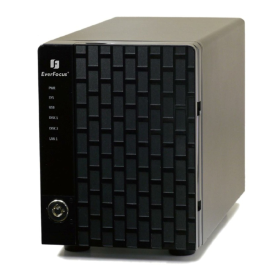
1. Installation 1.1 Installation Process Step 1: Unpack the Unit This package contains the following items: The unit Quick Start Guide Screws for disk drives Power cord 19V DC power transformer CD with Install Wizard, Backup, Live View, Playback, Verification ... - Page 10 4-bay unit front/rear view Reset System Status ; eSATA Status eSATA Conn. Ethernet 1 & 2 Activity 1& 2 DISK 1 & 2 Status DISK 3 & 4 Status USB Conn. Power Status RJ45 Network Conn. 1 & 2 Lock Cooling Fan Power Connection HDD Trays...
- Page 11 Step 4: Connect the Power 1. Attach the power cord from the power source to the power adapter. 2. Connect the power adapter to the back of the unit enclosure. See the rear view diagram. 3. On the front of the unit, press the power button. See the front view diagram.
- Page 12 Express Mode: In this mode, you don’t need to set up the network settings, Date/Time and RAID level. Advanced Mode: In this mode, configure all settings manually: network, license, camera, Date/Time, upgrade notification, and RAID level. 4. The Installation Wizard program starts searching for all the network devices on the LAN currently.
- Page 13 The default Administrator password is “admin”. 6. Name this server (the NVR) and write down its IP Address for finding it on the Internet in the future. Select the network type, and then click the button. Obtain network settings automatically from external DHCP server: ...
- Page 14 8. Add online cameras for this NVR. There are two ways of adding cameras – either click Search and select from the search list, or manually configure the cameras. Click the button after adding your cameras to the list – this will apply the settings and take you to the Manual camera setup page.
- Page 15 9. Set up the time zone, date, and time, and apply daylight saving changes if needed. Click the button.
- Page 16 10. Follow the following instructions and select the RAID type you want to create. Click the button. For a 2-bay unit, only RAID 0 and 1 are available. 11. Review your settings. If the settings are correct, click the Finish button to exit the settings procedure and activate the system.
-
Page 17: Led Status Definitions
1.2 LED Status Definitions Function LED Status Power Status Power-on: blue Power-off: dark System Status Healthy: blue Reset admin password: blue with blinking Unhealthy or abnormal temperature status: orange Reset to default setting: orange with blinking ... -
Page 18: Settings
2. Settings After setting up the unit, log into the DVR by entering its IP address in the browser (Internet Explorer 7 and later). When connecting, choose your language, enter the username and password, and then click the login icon. There are four main menu categories in this DVR’s GUI: Settings, Live View, Playback, and Logout. - Page 19 4. Click the Search button. 5. The system will list all the currently available cameras. Select a camera by clicking on it. Click the icon to add that camera to your camera list. 6. After clicking the camera’s icon, that camera’s setting page will pop up. Insert the camera name, username, and password.
-
Page 20: Add Cameras Manually
2.1.2 Add Cameras Manually 1. Open Internet Explorer and log into the NVR. 2. Click Settings / IP Camera / Camera Setting. 3. Click the Camera Settings tab. The Camera List will be displayed on the bottom of the page. 4. -
Page 21: Modify Camera Information
Note that the “username” field is called “Administrator Name” in this instance. This is because admin-level control is required in this setup procedure to ensure smooth interaction between the camera and the NVR. 6. Click the Save button. Save: Save the configuration of this camera. ... -
Page 22: Set Up Lens Settings
Camera Name: The name of the camera. Video Format: Choose the type of format which this camera supports. Frame rate: Select the frame rate of the camera. Resolution: Select the resolution of the camera. Quality: Select the image quality of the camera. ... -
Page 23: Set Up 2Nd Stream
If users enable the lens while lens is not installed correctly or not even installed, a warning message will pop up as a notification if users are trying to operate lens on liveview page. 2.1.6 Set up 2nd Stream The stream profile is designed for mobile clients and lower-fps live stream display. -
Page 24: Recording & Event Setup
Conn. Status: The status of the connection. Click the Connect or Disconnect button to change the connection status. Rec. Status: The set recording schedule of this camera in this time. Framerate: The frame rate of this camera. Bitrate: The transmission bit rate of this camera. -
Page 25: Recording Schedule / Event Setup
Automatic Recycle: Check the Enable option to recycle disk space automatically when the disk space is full. Keep Video: Set a period during which the recorded video clips will be kept intact. If you select both Automatic Recycle and Keep Video, Automatic Recycle will take priority. - Page 26 7. The default setting of the camera’s recording schedule is from 00:00 to 24:00. If you want to modify the time slot, click the Configure button to modify the default settings first. 8. Choose the recording mode. Always Record: Always record. ...
- Page 27 triggered by Motion or Digital input. When setting the event Motion, please first ensure that the motion detection function of the camera has been enabled. 9. If you want to add another new schedule, click the Insert button to add a new one.
-
Page 28: Camera Events And Responding Actions Setup
Drag Drag 2.2.3 Camera Events and Responding Actions Setup 1. Open Internet Explorer and log in to the unit. 2. Click Settings / Recording & Event / Event & Action Management. 3. Choose the camera, and then select one of the events. The event list depends on camera its own ability. - Page 29 Connect lost: When a connection between the camera and this unit is lost, the system will trigger an action. Motion from Camera: When video motion is detected, the camera triggers an action. Input: Any external input can trigger an action. ...
-
Page 30: I/O Box Input And Responding Action Setup
Output: When an event occurs, the system will send an output signal to other connected devices. E-Mail: When an event occurs, the system will send e-mail notifications. Make sure to add an e-mail address first. CMS: When an event occurs, the system will send out a signal to CMS. ... -
Page 31: System Events And Responding Actions Setup
Output: When an input is triggered, the system will send an output signal to other connected devices. E-Mail: When an input is triggered, the system will send e-mail notifications. Make sure to add an e-mail address first. CMS: When an input is triggered, the system will send out a signal to ... - Page 32 Abnormal disk status: When there is no enough disk space for recording or when disk is abnormal for accessing, the system will trigger an action. Daily System Report: Enable users to know the system information, HDD usage, and Disk status everyday through E-mail without accessing to the unit to check.
-
Page 33: Smtp Server Setup
2.2.6 SMTP Server Setup 1. Open Internet Explorer and log in to the unit. 2. Click Settings / Recording & Event / E-Mail. 3. Click the SMTP Server tab. Server Address: SMTP (Simple Mail Transport Protocol) server IP address. Port: SMTP port. -
Page 34: Add Event Contacts
2.2.7 Add Event Contacts 1. Open Internet Explorer and log in to the unit. 2. Click Settings / Recording & Event / E-Mail. 3. Click the Contactors tab. Contactor: Add this new contact into the contact list. Reset: Return to the latest saved settings of the contact list. ... - Page 35 4. Choose the RAID level you prefer for your disk array. 5. Check boxes of disks and click the >> button to assign disk drives for this volume. 6. Click the Create button. A confirmation dialog pops up. Check the Yes, I want to create volume with those disk(s) box, and click the Yes, create it button.
-
Page 36: View Raid Volume Status
The RAID Volume will be functional on another unit if all disks of this volume are moved to the unit. After setting RAID level, you are not allowed to change neither the RAID level nor the number of disks containing in this volume. To reduce the possibility of having problems to access public folder via My Network Places, before creating new disk volume or modifying volume, please delete the invalid... -
Page 37: View Disk Drive Information
RAID Level: RAID 0, 1, 5, or 10, specified when it was created. RAID Status: Functional is normal. Critical means there are some problems on RAID volume, but the recording status is normal. Offline means that no volume is found, so recording is stopped and you cannot access your data either. - Page 38 This function is not applied to RAID 0, since there is no data protection mechanism by its nature. In case of any unexpected damage, we recommend users to unplug running HDD by this method, which can be viewed as security hard drive remove. 1.
- Page 39 5. After removing the damaged disk. Add a free disk to replace the damaged, and click the Modify button. 6. A confirmation dialog pops up. Check the Yes, I want to modify this volume box, and click the Yes, modify it button. 7.
-
Page 40: Delete A Raid Volume
2.3.5 Delete a RAID Volume Open Internet Explorer and log in to the unit. Click Settings / RAID & File System / RAID Management. Click the Delete tab. Click the option button beside the RAID Volume you want to delete. Click the Delete button. -
Page 41: Format
When you delete a RAID Volume, all the folders in the RAID volume and all the data saved in the folders will be deleted. Backup any important data before deleting a RAID Volume. 2.3.6 Format Neither pressing reset button nor loading default setting, the data of RAID volume won’t be deleted, which implies that format is the only way to clean the RAID information from disks. -
Page 42: Modify The Ftp Protocol Settings
1. Open Internet Explorer and log in to the unit. 2. Click Settings / RAID & File System / Protocol Control. 3. Click the Windows tab. 4. Check and enter the unit’s information. 5. Click the OK button. Services: Enable to let users access this unit through Windows Explorer. ... -
Page 43: Auto Backup
Passive Ports: The data transmission port of passive mode. 2.4 Auto Backup This feature enables you to automatically backup the recorded video of the previous date to FTP site. There are two steps to enable the function, one is Set up Backup Schedule, another is Set up Backup Server. -
Page 44: Set Up Backup Server
the next file. If the connection is lost, the system would wait for the connection, so no file would be skipped. 2.4.2 Set up Backup Server 1. Open Internet Explorer and log in to the unit. 2. Click RAID & File System / Auto Backup Management. 3. -
Page 45: Network Setup
6. Click the Save button. Make sure the FTP account with privileges of administrator who is able to upload, rewrite, delete files, and create new folder. Besides, make sure the FTP server has enough space for auto backup. To avoid the failure of auto backup, please check the normality of FTP server regularly (e.g., enough space for video, system conditions.) 2.5 Network Setup 2.5.1 View Network Status... - Page 46 Server Name: Name your unit. Because of the internal data modifications required, it takes a few seconds to change the name of your unit. Log in again after configuration activated. Internet Protocol: Choose to obtain an IP address from external DHCP ...
-
Page 47: Auto Port-Forwarding
2.5.3 Auto Port-Forwarding This function is designed for saving time in port configuration on router if users want to access the unit (in LAN) from WAN. Once enabling UPnP Service on router, users can do port-forwarding for setting page (default: 80), liveview (default: 5150), playback (default: 5160), and CMS (default: 5170) automatically. - Page 48 6. After selecting one of searched routers, click the icon to set up port-forwarding to this router automatically. You will find ports of setting, liveview, playback and CMS are listed. For security reason, the privilege of UPnP port-forwarding is LOWER than port-forwarding configured on router.
-
Page 49: Network Service Setup
UPnP port-forwarding is for temporarily use only. Most of UPnP router will clean up all UPnP ports after router reboots. Furthermore, for some routers, if the port you want to add has already been used for other devices in the same way (UPnP port forwarding), this “enable”... -
Page 50: Cms Service Setup
Port: Playback transmission port. Maximum Users: The number of users who can access playback functions at the same time. (Max: 8) Access: Check to record playback access information on NVR Log page, including access time, playback video channels, and time frame. Allowed/ Blocked List ... -
Page 51: Create New Users
4. The list will be displayed on the bottom of the page. 2.6.2 Create New Users 1. Open Internet Explorer and login the unit. 2. Click Management/ User Management. 3. Click the Create New Users tab. 4. Insert the username of this new user. 5. -
Page 52: Modify User Information
“Administrator” account, nor another username named “admin”. 2.6.3 Modify User Information 1. Open Internet Explorer and log in to the unit. 2. Click Management / User Management. 3. Click the Modify Users tab. 4. Click one of the users in the User List on the bottom of this page. 5. -
Page 53: Delete Users
4. Choose the user. 5. Enter a new password. 6. Enter this new password again. 7. Click the OK button. 2.6.5 Delete Users Except for the administrator, you can delete any users with the following steps. 1. Open Internet Explorer and log in to the unit. 2. -
Page 54: Offline License Activation
3. Select Online as the Activation Type, input serial number, and click the Activate button. 4. The license will be updated in License List if activated successfully. System will reboot automatically. 2.6.7 Offline License Activation If the device is set up in Intranet (Local LAN) without Internet connection, there is another way to activate license. - Page 55 3. Click the Export button under the section of Offline Activation to export the information of this unit. 4. Download dialog pops up. Save the request file and take it to other PC which is connected to the Internet. Furthermore, the PC should be installed OffLineTool.exe which can be found from NVR toolkit.
-
Page 56: View The Event Log
6. Input the serial number, click the Activate button, and save the .dll file offline_license.dll. 7. Import the license file to the unit. 8. The license will be updated in License List if activated successfully. System will reboot automatically. 2.6.8 View the Event Log 1. -
Page 57: Save Unit Configuration
There are four kinds of event which will be listed on this page. Hardware Log: The log information of the operations to your unit, such as reboot or shutdown. Log: The log information of the NVR system, such as system, ... -
Page 58: Load Unit Configuration / Default Settings
4. Check the box of E-Map Settings or POS Settings if you want to keep the configuration. 5. Click the OK button. 6. The configuration file will be generated into the chosen folder. 2.6.10 Load Unit Configuration / Default Settings Load configuration can let you apply another unit’s settings to the current unit;... -
Page 59: System
If there is POS database existed in the unit, loading configuration with different POS application config is likely to make the original POS data unsearchable. If the saved configuration is without E-map or POS settings, selecting loading configuration with E-map/POS settings will lead you get the default. The original E- map/POS settings (if any) are covered and untraceable. -
Page 60: Smart Fan Control
2.7.2 Smart Fan Control 1. Open Internet Explorer and log in to the unit. 2. Click System / System Settings. 3. Click the Fan Control tab. 4. Check the Enable or Disable option. 5. Click the OK button. 2.7.3 Buzzer Configuration There is a buzzer in the unit. -
Page 61: Upgrade The System
after power failure. 1. Attach the APC UPS to one of the unit’s USB ports. 2. Open Internet Explorer and log in to the unit. 3. Click System / Settings. 4. Click the APU UPS tab. 5. Check one of the options: Disable: Run until the UPS battery is depleted ... -
Page 62: System Date And Time Setup
4. Browse the FW for upgrading and click the OK button. 5. A confirmation dialog pops up. Click the OK button to start upgrade process. 6. After upgrade, the system will restart. You need to re-access the unit again after this. 2.7.6 System Date and Time Setup 1. -
Page 63: Restart The Unit
4. Check the Adjust clock for daylight saving changes option and select the time change of daylight saving time in your location. 5. Click the OK button. 2.7.8 Restart the Unit 1. Open Internet Explorer and log in to the unit. 2. - Page 64 3. Check the Shutdown option. 4. Click the OK button. 5. A confirmation dialog pops up. Click the OK button to shutdown the unit. Direct Shutdown 1. Open the lid of the unit. 2. Press and hold the power button for 2 seconds and release your hands when the buzzer is beeping once.
-
Page 65: Pos
3. POS 3.1 Introduction 3.1.1 System Introduction POS, a Point of Sales Systems based on NVR, provides financial transaction’s surveillance solution in one central system. The architecture is as below; POS transaction data flows to NVR by Ethernet. Each Cash Register with an external receipt printer is connected by DB9 cable. -
Page 66: Hardware Installation - Scb-C31A
Baud Rate 110 bps to 230.4 kbps Data Bits 5, 6, 7 or 8 Stop Bits 1, 1.5 or 2 Parity None, Even, Odd, Mark, Space Flow Control None, RTX/CTS, XON/XOFF, DTR/DSR 3.1.2 Hardware Installation – SCB-C31A To connect Cash Register, Printer, and SCB-C31A POS data capture converter together, please follow below steps: Step 1: Please refer the user manual to setup Cash Register and printer. -
Page 67: Software Installation - Scb-C31A
The LED Indicators: LINK LED: Ethernet cable connection and data active. RUN LED: System is ready (Blinking). Serial 1: Transiting/Receiving Indicator. 3.1.3 Software Installation – SCB-C31A Step 1: Use IE-browser to setup SCB-C31A, the default IP address is 192.168.1.1 Step 2: Setup IP address and password in Server page, and click the Save button. -
Page 68: Connection Via Tcp Client
Step 3: Setup Password if needed. Password is only using to activate a security feature on the serial server. Once a password is entered it will be required to access the menu and make change of configuration when access. Please write down the Serial number and MAC address, these two parameters are necessary when user forget your password. -
Page 69: Software Setup
3.2 Software Setup 3.2.1 Activate POS License If you are not the SCB-C31 user, you need to activate POS license before starting the following settings, please refer to License Activation for details. 3.2.2 NVR POS Setting 1. Open Internet Explorer and log in to the unit. 2. -
Page 70: Insert Pos Setting
Data Source: List of all the data sources. Insert: Click to insert POS and do the POS settings. See Insert POS Setting for details. Delete: Click to remove the selected POS from the list. See Delete POS Device for details. Configure: Click to configure the selected POS and modify the POS ... - Page 71 SCB-C31: The device possesses one POS license, and should be equipped with the cash register not working as TCP server. SCB-C31A: The difference from SCB-C31 is not possessing one POS license, so user should activate POS license. Client: Cash register possesses with network, so no need to have ...
-
Page 72: Delete Pos Device
5. Select Tag Filter. See Tag Filter for details. 6. Select the camera of Associated Cameras to display POS transaction data overlay on live video. 7. Set up display area for each camera video in Display Region Definition. Default: The default display area is in the upper left corner of video ... - Page 73 Data Tool: Clear/import/export buttons to clear/import/export the original and filtered data. Filter Tool: Upper/down buttons to arrange the priority of each filter; remove button to remove the filter from list. 3. Enter name of this tag filter. 4. Click Connect button to capture POS transaction data from POS device. The original transaction data will be shown on the left window.
- Page 74 Omit: Neglect the selected text which is meaningless or not important. The text will disappear on the right window. Substitute: Use another word(s) to replace the selected text. The system will pop up a substitution panel for replacing word(s) users want. The replaced text will be shown on the right window.
-
Page 75: Edit Tag Filter
End: Define the selected text as the symbol for transaction ending. The filtered data will be separated line as below. 7. Filter Tools Up: Move a tag filter up; the upper filter will be operated earlier. Down: Move a tag filter down; the lower filter will be operated ... -
Page 76: Import/Export Tag Filter
1. Select Tag Filter name from drop-down menu. 2. Click Delete button to delete it. 3.3.4 Import/Export Tag Filter 1. Click Import/Export button and select Import/Export URL. 2. Click Open/Save to Import/Export Tag Filter. 3. After importing tag filters, users can simply select tag filter from drop-down menu without editing new tag filter. -
Page 77: Remote Live Viewer
5. Click the OK button to save. 3.4.2 Remote Live Viewer 1. Startup > NVR > Remote Live Viewer 2. Click the General Setting button to open Live View Setting window. 3. Select the font, font size, font color and background for the POS transaction data overlaid the video. -
Page 78: Playback
4. Click the OK button to save. 3.4.3 Playback 1. Open Internet Explorer and log in to the unit. 2. Click the Playback button. 3. Click the Setting button to open Setting window. 4. Select the font, font size, font color and background for the POS transaction data overlaid the video. -
Page 79: Playback System
3.4.4 Playback System 1. Startup > NVR > Playback System 2. Click the Setting button to open Setting window. 3. Select the font, font size, font color and background for the POS transaction data overlaid the video. Also, select the type of transaction data display time. -
Page 80: Pos Transaction Data Search
3.5 POS Transaction Data Search POS Search tool is used to search key word of all transaction data. 3.5.1 Search POS Transaction Data through Playback 1. Open Internet Explorer and log in to the unit. 2. Click the Playback button. 3. -
Page 81: Search Pos Transaction Data Through Playback System
4. Click the POS Search button to open POS Search Dialog window. 5. Select a POS device(s) from the POS list. 6. Set up Start Time and End Time in Data Time Period section. 7. Enter the keyword you want to search. 8. -
Page 82: Select Period By Pos Search
3.6.1 Select Period by POS Search 1. Refer to POS Transaction Data Search. 2. Select the transaction data from the result list, and click OK. 3. The period you select from POS search results will be selected automatically. 4. Click OK to playback videos. 3.6.2 Select Period by Data &... -
Page 83: Backup Video With Pos Data
the server users want to access. 4. Highlight the video clip you want to review by left-clicking and dragging the time period. You may also utilize the Start Time and End Time in Date Time Period section after choosing cameras. 5. -
Page 84: Backup Through Playback System
3.7.2 Backup through Playback System 1. Startup > NVR > Playback System. 2. Click the Open Record button to select data. 3. Click the Backup button. 4. Check the Backup POS Transaction option. 5. Set the Start Time and End Time you want to backup. 6. -
Page 85: Introduction
4. I/O 4.1 Introduction 4.1.1 System Introduction We provides remote I/O solution for NVR by connecting SCB-C31 with I/O Box SCB-C24/26/28. Refer to the below architecture, I/O device is connected directly with I/O Box, and input/output signal delivered in RS485 format are converted to Ethernet through SCB-C31. -
Page 86: Software Installation - Scb-C31
RS485 RJ-45 RS485 Reset Switch Power Multiple I/O Boxes can be connected to a single SCB-C31. However, series connection of I/O boxes is forbidden. Furthermore, the default ID for each I/O Box is the same. Please follow the direction to setup I/O Box one by one. 4.1.3 Software Installation –... -
Page 87: Software Installation - Scb-C24/26/28
2. Server Listening Port: The default port is 4000, which is not the port for setting page, but for signal transmission. Step 3: Click the Apply button to activate configuration. Due to the stability of data transmission, one SCB-C31 can be paired with one NVR unit only. - Page 88 IOConfig.exe starts scanning the ID from 0 to 255, and it may take around a minute to finish scan. 2. When the I/O Box is discovered, click on the item and change the ID from the New Address field. Click the Update device button to activate the settings.
-
Page 89: Software Setup
4. Refer to the HW Installation section to connect other I/O Box and repeat the steps 1 through 3 above to configure more I/O Boxes. 4.2 Software Setup 4.2.1 Add I/O Box 1. Open Internet Explorer and log in to the unit. 2. -
Page 90: Modify I/O Box Information
Port: The transmission port of SCB-C31. ID: The ID of the I/O box. 4. Click the Create button, and the information will be updated in I/O Box List. 5. Repeat steps 3 and 4 to add more I/O boxes in the list. 6. -
Page 91: Relative Configuration And Application
4. Click the Save button. If the box of I/O pin is unchecked, this pin won’t be shown on relative application pages. In other words, you cannot do any setting/operation with this pin. See details in next section. 4.3 Relative Configuration and Application 4.3.1 Record on Input Trigger Refer to Recording Schedule / Event... -
Page 92: Live View
5. Live view There are two ways to execute the live view function: with Internet Explorer or with the Remote Live Viewer application. 5.1 Internet Explorer 5.1.1 Live View Control Panel Camera List Log In/ Log Out (Live view service) PTZ Camera Control Set Preset Point /... - Page 93 server name, video current status, and bit rate for a selected channel. Start Menu > E-Map: Upload map and drag camera or I/O on it to track device location and alarm status with instant response when an event occurred. See details in the chapter of E-Map.
- Page 94 Enable Move: Adjust the current view of camera which supports PT function by dragging the button on the display screen. Enable Digital PTZ: Click the + or – button to zoom in or zoom out the view. The lower right square flashing on the video grid indicates the correspondent view of the camera.
-
Page 95: Live View Setting
without failing to record the whole view. Connect / Disconnect: Click to connect or disconnect the designate camera. Login / Logout Server: Click to login or logout. Connect All / Disconnect All: Click to connect or disconnect all ... -
Page 96: Stream Profile Setting
5. Check the Enable audio on active channel option to enable audio streaming on active channel. This function synchronizes with right click on camera to enable audio. 6. Check Synchronize video frames to avoid the tearing problem occurring in video display while increasing the CPU loading. 7. -
Page 97: Osd (On-Screen Display) Setting
setting page. 6. Click a camera and select its stream profile, and click the Copy to… button to apply this profile to other channels. 7. Click the OK button. 5.1.5 OSD (On-screen display) Setting 1. Open Internet Explorer and log in to the unit. 2. -
Page 98: Notification
Auto Scan Layout 5. Select Primary channel which will always be on the screen when activating auto scan; while select Secondary channel which has second priority when activating auto scan. Enter the time interval for auto scan. 6. Select the screen division of NxN type. 7. -
Page 99: Set Up Joystick Control
5. Check Show recording status to show the crystal ball with recording status on monitor display. 6. Check Show camera event to display the words of detected camera event on the correspondent screen. 7. Check Popup system event to pop up system event message dialog as a warning when a system event occurred. -
Page 100: Set Up Live View Sound On Event
Parameter: Choose the preset point from the drop-down menu. Default: Click to back to default setting. Import: Click to import the settings. Export: Click to export the settings. 5. Click the OK button. 5.1.9 Set up Live View Sound on Event 1. -
Page 101: Remote Live Viewer Application
5. Check the Enable playing sound on event option. 6. Select sound file, default sound or user defined sound (.wav). 7. Click the OK button. The function only activates on event, which means you have to setup camera motion, camera I/O and I/O Box I/O as an event. Refer to Event &... - Page 102 click the button to set up this view as preset point. Repeat the process to add more preset points. Click the button to see the preset view. Zoom: Click the + or – button to zoom in or zoom out the view. ...
- Page 103 Enable Move: Adjust the current view of camera which supports PT function by dragging the button on the display screen. Enable Digital PTZ: Click the + or – button to zoom in or zoom out the view. The lower right square flashing on the video grid indicates the correspondent view of the camera.
-
Page 104: Unit Connection Setting
Connect / Disconnect: Click to connect or disconnect the designate camera. Login / Logout Server: Click to login or logout. Connect All / Disconnect All: Click to connect or disconnect all cameras. 5.2.2 Unit Connection Setting 1. Startup > NVR > Remote Live Viewer. 2. -
Page 105: General Setting
5. Insert the IP address. 6. Modify the port if necessary. 7. Insert the user name. 8. Insert the password. 9. Check the Save Password / Auto login option. 10. Click the Test Server button to test the connection between the local application and the remote unit. - Page 106 3. Click the General tab. 4. Check the Enable audio on active channel option to enable audio streaming on active channel. This function synchronizes with right click on camera to enable audio. 5. Check Synchronize video frames to avoid the tearing problem occurring in video display while increasing the CPU loading.
-
Page 107: Camera Group Setting
5.2.4 Camera Group Setting You can put different cameras into the same group. 1. Startup > NVR > Remote Live Viewer. 2. Click the General Setting button. 3. Click the Group tab. 4. Log in to all the servers that contain the camera(s) you would like to put into the group(s). -
Page 108: Stream Profile Setting
5.2.6 Stream Profile Setting Select the preferred stream type of each camera as default live view profile. 1. Startup > NVR > Remote Live Viewer. 2. Click the General Setting button. 3. Click the Camera tab. 4. Adjust the stream profile of every camera with stream profile enabled in the setting page. -
Page 109: Monitor Display Setting
4. Check the Enable camera OSD option. 5. Set the foreground and background settings of the OSD. 6. Select which kinds of information will be displayed on the screen. 7. Click the Apply button to preview the result. 8. Click the Default button to back to the default settings if necessary. 9. -
Page 110: Notification
4. Select appointed server group to activate auto scan. 5. Select Primary channel which will always be on the screen when activating auto scan; while select Secondary channel which has second priority when activating auto scan. Enter the time interval for auto scan. 6. -
Page 111: Set Up Joystick Control
5.2.10 Set up Joystick Control 1. Startup > NVR > Remote Live Viewer. 2. Click the General Setting button. 3. Click the Joystick tab. Function: You can choose the function from the drop-down menu for the button of the joystick. Parameter: Choose the preset point from the drop-down menu. -
Page 112: Set Up Live View Sound On Event
4. Click the OK button. 5.2.11 Set up Live View Sound on Event 1. Startup > NVR > Remote Live Viewer. 2. Click the General Setting button. 3. Click the Sound tab. 4. Check the Enable playing sound on event option. 5. -
Page 113: E-Map
6. E-Map There are two ways to execute the live view function: by Internet Explorer or by Remote Live Viewer application. With E-map, user can easily track the device location and alarm status with instant response when an event occurs. The arrows and lightening icon on E-map represent cameras and I/O devices. -
Page 114: Add Map
E-map. Digital Input: Select it to highlight the device with green ring on map and show status on Information Window. If the Digital Input is from IP camera, the preview window will display live video of the camera. Digital Output: Select it to highlight the device with green ring on ... -
Page 115: Edit Map
5. Repeat steps 2 through 4 to add more maps. 6. Click the Upload button to activate all the settings. The maximum file size of each map is 500KB. There are 10 layers of map, and the map capacity of each layer is 10. 6.1.3 Edit Map 1. -
Page 116: Layout Adjustment
Adjust the Layout 6.1.7 Layout Adjustment Adjust the Layout: Click the triangular indicator to hide the Device and Map Tree List / Preview and Information Window on right and left side of the window. Click the indicator again to back to the default. Maximize the Map: Click the icon on the upper right to get the full ... -
Page 117: Remote Live Viewer Application
6.2 Remote Live Viewer Application 1. Startup > NVR > Remote Live Viewer. 2. Click the Start Monitor button and select Open E-Map. 6.2.1 E-Map Control Panel Server List Edit Mode / Browse Mode Switch Button E-Map Picture Preview Window and Information Device and Map Tree List Server List: Select a server to display the E-map of the server. -
Page 118: Playback
7. Playback There are two ways to execute the playback function: with Internet Explorer or with the Playback System application. 7.1 Internet Explorer 7.1.1 Playback Control Panel Browse Mode Search Mode General Setting Open Record Enhancement / Backup Post Processing Tool Export Video / Save Image... - Page 119 Open Record: Click the Open Record button to access the Date-Time Panel and select the video records which you want to review. General Setting Record Display Calendar View: view the Record Display Window as a calendar. List Control: view the Record Display Window as a list control.
-
Page 120: Search The Recorded Video
7.1.2 Search the Recorded Video Refresh POS Search Previous/ Next Video Preview Recording Date Record Display Window Date Time Period Time Table Recording Types : refresh the Record Display Window. : go to previous or next recording date. Record Display Window: Display the available recorded video records. -
Page 121: Play The Recorded Video
1. From the Record Display Window at the top left of the Date Time Panel, select the date you want to search the record from. The red lines shown on the time table indicate available recorded video records. 2. Use color bars to differentiate recording types from each other. This will help you select video clips. - Page 122 General Motion: Detect all movements in the defined area. 1. Define detection zone by dragging to draw a detection zone. You may define more than one zone by repeating this step. 2. Modify the sensitivity setting by changing the slider control.
-
Page 123: Recorded Video Enhancement
7.1.5 Recorded Video Enhancement 1. Open Internet Explorer and log in to the unit. 2. Click the Playback button on the top of the page. 3. Click the Open Record button. 4. The Record Display Window will show the information of the available video clips. -
Page 124: Save A Video
7.1.6 Save a Video 1. Open Internet Explorer and log in to the unit. 2. Click the Playback button on the top of the page. 3. Click the Open Record button. 4. The Record Display Window will show the information of the available video clips. -
Page 125: Save An Image
13. Check to export the recorded video with Audio, OSD and POS Transaction. 14. Click the OK button. We recommend that you export to the .asf format when saving video. In exporting to the .avi format, the frame rate will be increased when playing in the video player, causing the video to run faster than normal. -
Page 126: Backup The Recorded Video
Print Content: Print the image from currently selected channel or all the channels shown on the screen. Page Setting Print in original size: Check to have the image print in original size. Fit the page: Check to have the image fit the page. ... -
Page 127: Remote Playback System Application
4. Set the Start Time and End Time you want to backup. 5. Select the cameras you want to backup. 6. Select the directory you want to save the backup data. 7. Click the Backup button. 8. The system will then begin backup process automatically. 7.2 Remote Playback System Application 7.2.1 Playback System Application Control Panel The Playback System control panel is similar to the playback panel in... -
Page 128: Set Up Unit Connections
Browse Mode Search Mode General Setting Open Record Enhancement / Backup Post Processing Tool Export Video / Save Image Audio Print Screen Division Zoom Information Minimize Exit Speed Display Window Stop / Play / Pause Audio Volume Control Step Backward/Forward Frame(s) Previous/Next Interval 7.2.2 Set up Unit Connections Before using the Playback System application, you need to set a connection... -
Page 129: Search The Recorded Video
4. Insert the name of your unit. 5. Insert the IP address of that unit. 6. Modify the port if necessary. 7. Insert the user name. 8. Insert the password. 9. Check the Save Password option. 10. Click the Test Server button to test the connection between the local application and the remote unit. -
Page 130: Play The Recorded Video
1. Startup > NVR > Playback System. 2. Click the Open Record button. 3. Click the icon on the top of the Date-Time Panel to obtain the Remote Playback Site Management dialog, and then select the server you want to access. -
Page 131: Recorded Video Enhancement
8. The searched events will be listed. Click to find that event. There are 5 types of unusual events: General Motion, Foreign Object, Missing Object, Focus Lost, and Camera Occlusion. General Motion: Detect all movements in the defined area. Foreign Object: Alarm when any additional object appears in the ... -
Page 132: Save A Video
Brightness: Check the option to activate the function. Move the slider control to the right to make the image brighter. Contrast: Check the option to activate the function. Move the slider control to the right to increase contrast. Grey Scale: Check the option to show the record in gray-scale mode so ... -
Page 133: Save An Image
7.2.8 Save an Image 1. Startup > NVR > Playback System. 2. Click the Open Record button. 3. The Record Display Window will show the information of the available video clips. Select the date from which you want to search the record. Check Search the Recorded Video for more details. -
Page 134: Backup The Recorded Video
7.2.10 Backup the Recorded Video Different from Save Video, the Backup function will save all the recorded videos which belong to the time slot you set, instead of the clips. 1. Startup > NVR > Playback System. 2. Click the Open Record button to select data. 3. -
Page 135: Backup And Delete Records
8. Backup and Delete Records 8.1 The Backup System Application In addition to the ways mentioned in the previous chapters, you can apply the application to backup your files. 1. Startup > NVR > Backup System. 2. Click the Remote Server Site button to set up remote server. - Page 136 6. Insert the user name. 7. Insert the password. 8. Check the Save Password option. 9. Click the Test Server button to test the connection between the local application and the remote unit. 10. Click the Add button to add this unit into the remote server list. 11.
-
Page 137: Backup The Recorded Video Through Windows Explorer
17. Select the time slot which you want to backup. 18. Click the Backup button. 19. Select the way and directory you want to save the backup data. 20. Check the Include Playback application option, which will add Playback application into the backup folder. 21. -
Page 138: Backup The Recorded Video Through Ftp
4. Select the volume and open the “VIDEODATA” folder. 5. Copy the date folder which you want to backup to your desktop / laptop. 8.3 Backup the Recorded Video through FTP 1. Find your unit through Windows Explorer (insert “ftp://” plus the IP address of your unit) 2. - Page 139 2. Click the Remote Server Site button to set up remote server. 3. Insert the name of your unit. 4. Insert the IP address of that unit. 5. Modify the port if necessary. 6. Insert the user name. 7. Insert the password. 8.
- Page 140 13. Click the New Period button to select the record date. 14. Set the Start Time and End Time. (or highlight the video records which you want to delete) 15. Select the cameras you want to delete the records. 16. Click the OK button. 17.
-
Page 141: Without Backup Application
18. Click the Delete button. 19. Confirm the check dialog. 8.5.2 Without Backup Application 1. Find your unit through Windows Explorer (insert “\\” plus the IP address of your unit). 2. Open the “public” folder. 3. Insert the name and password of the administrator. 4. -
Page 142: Verification Tool
9. Verification Tool The Verification Tool verifies whether the data created by the system has been tampered with. It’s the process by which a digital watermark (a digital signature) is added to each recorded video frame to ensure its authenticity. There are three types of data could be verified by Verification Tool: 1. -
Page 143: Verify Image / Video
Video Preview: Preview designate file in verification list. Select the buttons below to play , pause , and stop the video file. 9.2 Verify Image / Video 1. Select single or multiple files for verification. 2. Click the Verify button to start verification. -
Page 144: Log Out
10. Log out Click the Logout button on the top of the page to log out of the system. If there is no action in 10 minutes, the system will log out automatically to avoid unauthorized access. -
Page 145: Remote Pc System Requirements
11. Remote PC System Requirements Remote PC Minimum Requirements Model 2/4 bay Windows XP 32 bit, Windows 7 32/64 bit Supported Intel Core 2 Duo, 2.6GHz User 1. HTTP Web browser - Internet Explorer 7 and Interface later 2. NVR Client application program... -
Page 146: Troubleshooting
12. Troubleshooting 12.1 Replace a Failed Disk Drive If a disk drive fails, the Disk Status LED becomes orange. If the disk drive belongs to a RAID Volume, the Volume goes Critical or Offline, depending on RAID level. See Check RAID Volume Status for details. -
Page 147: Restore All Default Configuration
buzzer beeps one time and the System Status LED flashes in blue. 4. System will restart and the Administrator’s password is now reset to admin. 12.5 Restore All Default Configuration If you want to restore all configurations to default setting, follow the following steps. -
Page 148: Cannot Log In To The Unit With Internet Explorer
5. Click the Install button to complete the process. 12.7 Cannot Log in to the Unit with Internet Explorer 1. Check the settings of your antivirus software. 2. Change to appropriate settings or turn off this antivirus software. -
Page 149: Appendix - Raid System
Appendix – RAID System Introduction to RAID RAID (Redundant Array of Independent Disks) allows multiple disk drives to be combined together into a RAID Volume. You will create a RAID Volume on your unit when you perform the setup procedure. The benefits of a RAID can include: Higher data transfer rates for increased server performance ... -
Page 150: Raid 1 - Mirror
If disk drives of different capacities are used, there will also be unused capacity on the larger drives. Because RAID 0 does not offer Fault Tolerance, meaning that you cannot recover your data after a disk drive failure, we do not recommend a RAID 0 Volume for your unit. -
Page 151: Raid 5 - Block Striping With Distributed Parity
RAID 1 Volumes on this unit consist of two disk drives. If you want a mirrored RAID Volume with more than two disk drives, see RAID 10 – Mirror / Stripe for details. RAID 5 – Block Striping with Distributed Parity RAID 5 organizes block data and parity data across the disk drives. -
Page 152: Choosing A Raid Level
The data capacity RAID 10 Volume equals the capacity of the smallest disk drive times the number of disk drives, divided by two. In some cases, RAID 10 offers double fault tolerance, depending on which disk drives fail. RAID 10 Volumes on this unit consist of four disk drives. Because all of the available disk drives are used for the RAID Volume, you cannot set up a spare drive with RAID 10. - Page 153 improved by spreading the I/O being lost load across many channels and Should not be used in mission drives critical environments No parity calculation overhead is involved RAID 1 Advantage Disadvantage Simplest RAID storage subsystem Very high disk overhead - uses ...
-
Page 154: Appendix - Camera Integration
For performance consideration, we fix the resolution and framerate for each brand/series. The list will be updated every version. Low Profile Minimum Profile Brand/Series Resolution Framerate Resolution Framerate EverFocus (ONVIF) QCIF~UXGA 0.1~6 QCIF~UXGA 0.1~6 EverFocus (Others) QVGA QVGA ACTi Arecont... - Page 155 0.1~10 QCIF~D1 0.1~10 series) Zavio QCIF Zavio (Mega) EverFocus (ONVIF): EQN2200, EQN2201 Eneo 1: GLS-1701/IR Eneo 2: GLS-2104 Eneo 3: GLS-2301H Eneo 4: NLC-1401, NLD-1401, NLS-1401 Eneo 5: NXC-1301M, NXC-1302M, NXC-1401M, NXC-1402M, NXD-1301M, NXD-1302M, NXD-1401M, NXD-1402M Sanyo HD1: VCC-HD2500, VDC-HD3500...
- Page 156 Sanyo HD4: VCC-HD4600 Videosec 1: IBF-211, IDA-210, IP-206M, IS-240 Videosec 2: ICS-13, ICS-20F, ID-20...
- Page 157 EverFocus USA - California: EverFocus USA - New York: 1801 Highland Avenue, Unit A, Duarte, CA 91010, 415 Oser Avenue, Unit S, Hauppauge, NY 11788, USA TEL: +1 631 436 5070 TEL: +1 626 844 8888...
Need help?
Do you have a question about the NVR and is the answer not in the manual?
Questions and answers