Table of Contents
Advertisement
Advertisement
Table of Contents

Related Manuals for EverFocus EDVR SERIES


Summary of Contents for EverFocus EDVR SERIES
- Page 1 Instruction Manual 16/9/4 Channel Digital Video Recorder EDVR SERIES...
- Page 2 © 2005 EverFocus Electronics Corp www.everfocus.com All rights reserved. No part of the contents of this manual may be reproduced or transmitted in any form or by any means without written permission of the Everfocus Electronics Corporation. Release Date: Dec. 2006...
- Page 3 Federal Communication Commission Interference Statement This equipment has been tested and found to comply with the limits for a Class B digital device, pursuant to Part 15 of the FCC Rules. These limits are designed to provide reasonable protection against harmful interference in a residential installation. This equipment generates, uses and can radiate radio frequency energy and, if not installed and used in accordance with the instructions, may cause harmful interference to radio communications.
- Page 4 CE Declaration This equipment has been tested and found to comply with the limits for a CE Class A digital device. The changes or modifications not expressly approved by the party responsible for compliance could void the user’s authority to operate the equipment. In a domestic environment this product may cause radio interference.
-
Page 5: Table Of Contents
2. INSTALLATION...14 2.1 Packing ...14 2.2 System Floorplan ...14 2.3 Basic Wiring Instructions...15 Final Install Process ...16 3. DVR MENU SETUP ...17 3.1 Time/Date Setup Menu ...18 3.2 Camera Setup Menu...22 3.3 Record Setup Menu ...27 3.4 Alarm Setup Menu ...29 3.5 Motion Setup Menu...32... - Page 6 4.1 Instant (N) Recording Setup ...66 4.2 Schedule Recording Setup ...67 4.3 Event Recording Setup ...68 5. PLAYBACK OVERVIEW...72 5.1 Basic Playback ...72 5.2 Search Playback ...75 6. COPYING VIDEO...78 6.1 Viewing a Copied File ...80 7. CALL OVERVIEW...81 8. SCREEN DISPLAY SETTING & MODE...82 8.1 Mode Button ...84 9.
- Page 7 APPENDIX C: RJ45 (RS485) PIN ASSIGNMENT...131 APPENDIX D: LAPSE MODE RECORDING TABLE ...132 TROUBLESHOOTING ...136...
-
Page 8: Safety Warning
Safety Warning WARNING To reduce risk of fire or electric shock, do not expose this appliance to rain or moisture. CAUTION Do not remove cover. No user serviceable parts inside. Refer servicing to qualified service personnel. Note: This equipment has been tested and found to comply with the limits for a Class A digital device, The changes or modifications not expressly approved by the party responsible for compliance could void the user's authority to operate... -
Page 9: Safety Precautions
Do not operate the appliance beyond its specified temperature, humidity or power source ratings. Do not use the appliance in an extreme environment where high temperature or high humidity exists. Use the appliance at temperature within indoor type DVR for 0 C ~ +40 C and a humidity below... - Page 10 Safety Precautions Read Instruction All the safety and operating instructions should be read before the unit is operated. Retain Instructions The safety and operating instructions should be retained for future reference. Heed Warnings All warnings on the unit and in the operating instructions should be adhered to. Follow Instructions All operating and use instructions should be followed.
-
Page 11: Product Overview
1. Product Overview The latest EverFocus digital video recorder generation is based on MPEG-4 compression technology, resulting in enhanced recording capacity and improved network image transmission speed with high image quality. Comprehensive features and extended event recording settings enable the almost universal application of this DVR series. -
Page 12: Specifications
D series: up to 2 internal 3.5” IDE Hard Disks Provide USB2.0: for external USB Flash Memory / for External Storage external DVD RW (Everfocus EPR200) D series: D(DVD) series has one built-in 3.5” DVD RW Recording Rate Please refer to **Note** at the following page... - Page 13 Yes, 2 x USB2.0 interface device. 1 for archiving & 1 for mouse. Ethernet Yes, RJ45 connectors for network communication USB for archiving Archive RS-485 for PTZ and/or control keyboard Power Source AC 100~240V Power F:70W; D:50W consumption Full size: 430mm (W) x 402.5mm (D) x 72mm (H) Dimension Weight 6.42 KG...
-
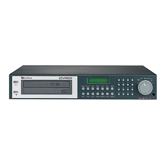
Page 14: Front Panel Keypads
Keys: ○ Press this key to start instant recording. ○ STOP Press this key to stop recording and playing back. ○ PLAY Play Back. ○ PAUSE Press this key to pause the playback picture. ○ SEARCH Press this key to enter the SEARCH MENU. ○... - Page 15 ○ SELECT Press this key to select, to assign a camera to a display, to adjust screen display, and so on. ○ MODE Switch PIP, 4, 7, 9, 10, 13 and 16 displays in Live and Playback modes. ○ ZOOM In full screen mode, 2x electronic zoom.
- Page 16 ○ CALL Press this key to enter and set up CALL MENU. ○ Menu Press this key to enter or quit MAIN SETUP MENU. ○ Shuttle and Jog Dial Shuttle: In the Playback mode, turn the Shuttle dial to fast forward/rewind the video.
- Page 17 ○ LCD Panel To display Date and Time, and other system information. ○ Remote Control IR remote control receiver.
-
Page 18: Back Panel Connections
For models: EDVR16D1/F1, EDVR16D2/F2, EDVR9D1/F1, EDVR4D1/F1 For model: EDVRD3 ○ ○ ○ ○ POWER ○ Main Power plug Connect power jack (AC 100~240V). ○ Audio IN Audio inputs 1~4 for recording, and it can be enabled by setting to “YES” or “NO” in the RECORD SETUP MENU. - Page 19 This connector is used for the main monitor display, a number of different display modes may be selected for viewing. ○ CALL MONITOR This connector is used for the call monitor. This monitor can only display a full screen, but not able to enter Setup Menu. VIDEO IN ○...
- Page 20 RS232 ○ RS232 connector 9-pin Sub-D control input/output for service purpose. RS485 ○ RS485 connector RJ 45 Connector to cascade multi Digital Video Recorder. ○ Connect to the monitor that has VGA input. Remote Control (extension cable is optional) ○ Remote Control Connector to connect IR extension cable that has an IR remote control receiver.
-
Page 21: Monitor Display
The status information of the cameras or machine will show up, and be located at different places on the screen. ○ Channel tag A channel tag indicates the channel name of the screen. ○ Event sign Event signals which are small icons with a capital letter and red background show the events on each screen. - Page 22 The sequence display is located on display with a “*” sign in the last display of the screen. The sign will replace “*” sign in the display when sequence occurs. Note: Sequence is invalid when the multiscreen display can show all the cameras. Temperature indication.
- Page 23 ○ Record status bar The record status bar appears when you enable a status bar on the screen (Please see 8 item of DISPLAY). Three parts which are current date, record status (% of space used for recording) and current time. Current Date Record Status Current date...
-
Page 24: Installation
2. Installation The installations described below should be done by qualified service personnel or system installers. Please check accessories in the packing before the Please refer to the following diagrams for the system connections. Note: Monitor and Camera must be purchased separately. installation. -
Page 25: Basic Wiring Instructions
1. Power Connect the power source or adapter into the power socket. 2. Cameras Connect each cameras video output to the video input on the digital video recorder shown in diagram 2.1. Note: At least one camera (CH 1) must be connected before the system is running for the auto detection of video standard to take effect. -
Page 26: Final Install Process
Once you have completed the basic wiring installation and the hard disk drive installation you are ready to turn on the DVR. Simply plug the power source you installed earlier. The POWER LED lights will light up if power is normal. The next step is to set up the menu... -
Page 27: Dvr Menu Setup
The following chapter will walk you through the detailed DVR Menu step by step and how to set the DVR for your specific application. To begin this process, press the MENU key. Once inside the main menu you will find there are 12 setup option pages as follows. -
Page 28: Time/Date Setup Menu
In the TIME/DATE SETUP MENU the following fields are defined as follows: 1. TIME FORMAT This field represents the time format on the DVR. There are two time formats that are 12 HOUR and 24 HOUR to be selected. 2. TIME This field represents the current time on the DVR. - Page 29 DVR. There are three date formats which are YYYY-MM-DD, MM-DD-YYYY and DD-MM-YYYY to be selected. 4. DATE This field represents the date on the DVR. To change this, simply use the Jog Dial on the DVR. There are three date formats which are YYYY-MM-DD, MM-DD-YYYY and DD-MM-YYYY to be selected.
- Page 30 Select “ON” or “OFF” to enable or disable time synchronize which can let you have correct time automatically when network is connected. To change this, simply use the Jog Dial on the DVR. 9. TIME SERVER You can set the time server address where you locate if you connect to network and enable time synchronize.
- Page 31 Under Dos Prompt, type “C:\Ping Pool.NTP.ORG to find out the IP address of NTP Server. TIME ZONE You can set the time zone where you locate if you connect to network and enable time synchronize. Atlantic Daylight Time subtract 3 hours from GMT Atlantic Standard Time subtract 4 hours from GMT Eastern Daylight Time subtract 4 hours from GMT Eastern Standard Time subtract 5 hours from GMT...
-
Page 32: Camera Setup Menu
Select PTZ ID/Address from 001~255 or OFF. The default value is 10+N where N is camera’s number. This ID must be the same as the ID used in PTZ Dip Switch. To change this, simply use the Jog Dial on the DVR. WEEK MONTH Diagram 3.4... - Page 33 However, the image is recorded, and can be played back by user who has playback right. The covert channels will not show up on the sequence mode. To change this, simply use the Jog Dial on the DVR. SEQ (MAIN/CALL) Setup a retention period for sequences.
- Page 34 720x480 Average size per image 720x240 Average size per image 360x240 Average size per image Note: Since the compression ratio of MPEG4 fully depends on the variation and complexity of the recorded video, the table above is for your reference only. REC SPEED ON TIME PERIOD: Scheduled recording time 1~8 which can be set in the SCHEDULE SETUP MENU.
- Page 35 IPS recording rate for manual or scheduled recording and recording controlled through “REC IN” input contact. The maximum image rate is limited to: Max. image rate per camera = max. DVR recording rate / number of installed cameras. Max. DVR recording rate depends on recording resolution:...
- Page 36 SUMMARY Dial Jog to change items in the SUMMERY table. All cameras’ statuses are shown in the SUMMARY table. The table is for checking camera overall statuses only, not for setting. Note: The SUMMARY table also exists in ALARM, MOTION and VLOSS SETUP MENU.
-
Page 37: Record Setup Menu
Diagram 3.6 is a screen shot of the RECORD SETUP MENU. This menu is for setting up the options for recording. We define recording as something on which sound or visual images have been recorded. In the RECORD SETUP MENU the following fields are defined as follows: RECORD AUDIO YES: Audio will be recorded when machine is recording. - Page 38 STOP: Stop recording when disk is full. AUTOWRITE WITHIN You can set DVR autowrite day, so that DVR will autowrite after the day number you set. If you do not wish to use this function, please set it OFF. IPS (N/P)
-
Page 39: Alarm Setup Menu
In the ALARM SETUP MENU the following fields are defined as: ALARM This field is to turn alarm detection ON or OFF. The default value is ON. To change this, simply use the Jog Dial on the DVR. ENABLE: Enable alarm detection. DISABLE: Disable alarm detection. - Page 40 The Default from the factory is set to on. To change this, simply use the Jog Dial on the DVR. Active camera setting, from camera 01~16. You can set the camera which corresponds to the place where the alarm is located.
- Page 41 10. ALARM NETWORK YES: Enable alarm network. NO: Disable alarm network. 11. MAIN MON: Display on a main monitor when an alarm occurs. NO CHANGE: No change on the display in the main monitor when an alarm occurs. FULLSCREEN: A full screen of the active camera will display when an alarm occurs. 12.
-
Page 42: Motion Setup Menu
In the MOTION SETUP MENU the following fields are defined as follows: MOTION: This field is to turn motion detection ON or OFF. The default value is Disable. To change this, simply use the Jog Dial on the DVR. ENABLE: Enable motion detection. DISABLE: Disable motion detection. - Page 43 1 = output signal 1 transmitted, 2 = output signal 2 transmitted, 3 = output signal 3 transmitted and 4 = output signal 4 transmitted. To change this, simply use the Jog Dial on the DVR. (Only EDVR16D3 model has 4 alarm outputs, all the rest models have only 1 alarm output).
- Page 44 Dial Jog to change items in the SUMMARY table. All alarm’s statuses are shown in SUMMARY tables. These tables are for checking alarm overall statuses, but not for setting. 11. Press SELECT to edit MOTION AREA. Enter a desired channel and press SELECT to edit a motion area.
- Page 45 EXIT MENU SELECT AREA COPY - CHANGE DIR ENTER - ON AREA SEARCH - OFF AREA PAUSE...
-
Page 46: Vloss Setup Menu
NO: Select NO if you do not wish to record Video Loss Events in the Log. DURATION Duration of Vloss buzzer ranges from 1 sec to 99 seconds. The default value is 5 seconds. To change this, simply use the Jog Dial on the DVR. Diagram 3.9... - Page 47 1 = output signal 1 transmitted, 2 = output signal 2 transmitted, 3 = output signal 3 transmitted and 4 = output signal 4 transmitted. To change this, simply use the Jog Dial on the DVR. (Only EDVR16D3 model has 4 alarm outputs, all the rest models have only 1 alarm output).
-
Page 48: Network Setup Menu
Please refer to the Networking Chapters (CH.10~13) of this manual to fully understand how to setup your network for this DVR. In the Network Setting Menu the following fields are defined as follows: Note: Since every Network Configuration is different, please contact your Network Administrator or ISP for how to assign those IP addresses and port numbers. - Page 49 PPPoE configuration. IP Address This field is to set a static IP Address for the DVR. A static IP address is an IP address whose value does not change. It is suggested to use a static IP address. If your Internet provider does not offer a static IP address you have the option to use a dynamic IP address.
- Page 50 DVR and client PC. Note: If you wish to have multiple users log into the DVR please open a range of ports on your router. For example if you use the default port 32760 you would open ports 32760-32763 on your router.
-
Page 51: Alarm (Network)
3.7.2 ALARM (NETWORK) DVR can send out Alarm message to an Alarm Server (PowerCon4). In the ALARM of the NETWORK SETUP MENU, we define: Note: Since every Network Configuration is different, please contact your Network Administrator or ISP for how to assign those IP addresses and port numbers. -
Page 52: Email
5. SERVER 2 Assign the IP address of Alarm server 2. 6. SERVER 3 Assign the IP address of Alarm server 3. 3.7.3 EMAIL In the EMAIL of the NETWORK SETUP MENU, we define: 1. SMTP SERVER Assign the SMTP (e-mail) server’s name. Note: please do not enter IP address. 2. - Page 53 “YES”, this e-mail address will receive a text message and an “ARV” format of a still image from DVR when Motion is triggered. This “ARV” file can be played back by opening “DVRViewer.exe” that you downloaded from the DVR or the Remote Viewer (Browser) or from the Copy Menu (labeled viewer).
-
Page 54: Password
1. Play: Allows the user to view live video, perform a search, playback and control the PTZ camera (if one is connected) 2. Live: Allows the user only to view live video To change this, simply use the Jog Dial on the DVR. Example: USER-NAME Password... -
Page 55: Pppoe
3.7.5 PPPoE In the PPPoE of the NETWORK SETUP MENU, we define: 1. USER User name that is provided by ISP for PPPoE Connection 2. PASSWD Password that is provided by ISP for PPPoE connection 3. PRIMARY DNS An IP address of DNS server that is provide by ISP. 4. - Page 56 NOTE: 1) Please complete all settings in PPPoE Setup Menu, then return to CONFIG for changing IP CONFIG to PPPoE. Otherwise, PPPoE settings won’t be valid. 2) If you select first PPPoE in IP CONFIG of CONFIG option, while PPPoE settings haven’t been done yet, then PPPoE function won’t work.
-
Page 57: Ddns
3.7.6 DDNS In DDNS of the NETWORK SETUP MENU, we define : For example: A user had applied for a DDNS account from Http://www.dyndns.org. User name: TEST Password: TEST Domain name ethin.dyndns.org. 1. SERVER DDNS provider. 2. USER User name of the account. 3. - Page 58 5. FQDN The domain name of this account. Users can connect to DVR that uses dynamic IP address by entering the domain name “ethne.dyndns.org” in IE browser. (This domain name is only an example, the DDNS account that user applies may differ from this example). They don’t have to know the IP...
-
Page 59: Schedule Setup Menu
Sun as default. You may choose from Mon-Sun as well as DLY. If you wish to create a daily timer for every day of the week you may choose the DLY option. To change this, simply use the Jog Dial on the DVR. MON (Monday), TUE (Tuesday), WED (Wednesday), THU (Thursday), FRI (Friday), SAT (Saturday), SUN (Sunday). - Page 60 This field is used to set the time you wish to start the timer recording. To change this, simply use the Jog Dial on the DVR. Hour: 0 ~ 23 in 24 hour time format; 1~12 in 12 hour time format.
-
Page 61: Disk Setup Menu
Diagram 3.18 is a screen shot of the DISK SETUP MENU. This menu is for viewing Disk information and formatting the disks. For every configuration change or initial setup we recommend formatting the Hard Disk. In the DISK SETUP MENU the following fields are defined as follows: 1. - Page 62 2. THERMOMETRIC SCALE Select CELSIUS or FAHRENHEIT for thermometric scale of the disk. 3. NO/SIZE/C or F/Start/End Time Show the number of drives, the size of each drive and the temperature as well as the days and times range stored on the hard drive. Note ○...
-
Page 63: Control Setup Menu
This field is to set the stop bit for the RS232 connection. There are two different stop bits, 1 or 2. The default in the DVR is set to 1. To change this, simply use the Jog Dial on the DVR. - Page 64 This field is to set the stop bit for the RS485 connection. There are two different stop bits, 1 or 2. The default in the DVR is set to 1. To change this, simply use the Jog Dial on the DVR.
-
Page 65: Warning Setup Menu
1 = output signal 1 transmitted, 2 = output signal 2 transmitted, 3 = output signal 3 transmitted and 4 = output signal 4 transmitted. To change this, simply use the Jog Dial on the DVR. (Only EDVR16D3 model has 4 alarm outputs, all the rest models have only 1 alarm output). - Page 66 3. ALARM DURATION Permanent 4. NETWORK ALARM YES: To enable network alarm. NO: To disable network alarm. 5. SEND EMAIL: YES: Send an email when the fan does not work. NO: Do not send an email when the fan does not work. The email address can be set in the NETWORK SETUP MENU.
-
Page 67: Hdd Temp
1 = output signal 1 transmitted, 2 = output signal 2 transmitted, 3 = output signal 3 transmitted and 4 = output signal 4 transmitted. To change this, simply use the Jog Dial on the DVR. (Only EDVR16D3 model has 4 alarm outputs, all the rest models have only 1 alarm output). - Page 68 5. SEND EMAIL YES: Send an email when HDD’s temperature is overheated. NO: Will not send an email when HDD’s temperature is overheated. The email address can be set in the NETWORK SETUP MENU. 6. STOP RECORD YES: Stop recording when HDD’s temperature is overheated. NO: Will not stop recording even when HDD’s temperature is overheated.
-
Page 69: No Hdd
1 = output signal 1 transmitted, 2 = output signal 2 transmitted, 3 = output signal 3 transmitted and 4 = output signal 4 transmitted. To change this, simply use the Jog Dial on the DVR. (Only EDVR16D3 model has 4 alarm outputs, all the rest models have only 1 alarm output). -
Page 70: Hdd Full
5. SEND EMAIL: YES: Send an email when no HDD has been found. NO: Will not send an email when no HDD has been found. The email address can be set in the NETWORK SETUP MENU. 3.11.4 HDD FULL In HDD FULL, we define: 1. - Page 71 Jog Dial on the DVR. (Only EDVR16D3 model has 4 alarm outputs, all the rest models have only 1 alarm output). 3. ALARM DURATION Buzzer noise and event record duration of an alarm, from 1 sec to 99 seconds. The default value is 5 seconds.
-
Page 72: System Setup Menu
YES: Turn the jog to enter the selection window, there are 4 options available: CANCEL, DEFAULT, LOAD, and SAVE. Select “CANCEL” for leaving the existing window. Select “DEFAULT” to load factory default values. Select “LOAD” to upload and save DVR configuration settings from USB. Select “SAVE” to save existing DVR configuration settings to USB device. - Page 73 NO: Press “ENTER” key to leave “LOAD/SAVE CONFIGURATION”. 4. UPDATE SYSTEM SOFTWARE: Turn the jog to enter the selection window. YES: Select YES to update system software from USB by pressing SELECT to start. NO: Select NO for canceling updating by pressing SELECT to start. Note: ○...
- Page 74 7. SYSTEM PASSWORD ENABLE YES: Select YES to enable the password function. NO: Select NO to disable the password function. 8. PASSWORD and RIGHTS: The login passwords here are used to operate and set up this machine locally not from the remote tcp/ip connection. The different login passwords indicate the different level of users, and no login name is necessary.
- Page 75 LEVEL-3 LEVEL ADMINISTRATOR DISPLAY MODE ZOOM SELECT CALL MENU COPY SEARCH PLAY STOP PAUSE Note: The above table will be updated if there is any change. User Level and Right LEVEL-2 LEVEL-1 OPERATOR GENERAL NONE ACCESS ----...
-
Page 76: Recording Overview
VCR. Scheduled recording (1~8) is based upon a set time period of when to begin & end the recording. Event recording would consist of an alarm or motion having taken place to trigger the DVR to record on that event. -
Page 77: Schedule Recording Setup
Note: If STOP key is pressed while machine is recording or playing video, the playing function will be disabled first. If STOP key is pressed twice the DVR will come out of record mode completely. Set up the DAY, START time, END time and then enable the SET in the SCHEDULE SETUP MENU. -
Page 78: Event Recording Setup
DVR it will begin recording at the specific IPS set under event column. Or when an alarm is detected by the DVR it will begin recording at the specific IPS set under event column. - Page 79 2. When the event and schedule are set, enter the CAMERA SETUP MENU to set the event recording speed (IPS) of the camera in the time period (TP) section. Diagram 4.3...
- Page 80 3. After enabling an event, you need to set a time period (TP) in the SCHEDULE SETUP MENU. An event recording must be set in a scheduled time period (TP). You can refer to the SCHEDULE SETUP MENU for time period configurations (Chapter 3.8). Note: ○...
- Page 81 DVR provides a record function which is triggered by external signal via the 19th pin of the ALARM INPUT / OUTPUT port. When the record input signal is pulled low constantly, DVR will start to record. The system will stop recording when the record input signal is not pulled low.
-
Page 82: Playback Overview
5. Playback Overview Before continuing please be sure to have reviewed DVR Menu Setup (Chapter 3). You are now ready to begin setting up the DVR for playback. This chapter will show you how to setup the recorder for basic playback. - Page 83 (3) Fast Forward/Reverse Playback Press the PLAY key to begin playing back process. Turn the Shuttle dial clockwise, to begin fast forward playback. PLAY The speed will be shown on the status bar of the bottom screen. >> 2, 4, 6, 8, 16, 32, 600X, and press ENTER at the same time to hold the play speed.
- Page 84 (5) Image advance Forward/Reverse Press PAUSE key to freeze the picture. PAUSE Turn the Jog dial clockwise to advance the still video image by image. Turn the Jog dial counterclockwise to rewind the still video image by image. The field feed speed will increase if the Jog dial is turned quickly.
-
Page 85: Search Playback
Press the SEARCH key to enter the SEARCH MENU. SEARCH In the SEARCH MENU, Dial the Jog clockwise or counterclockwise to change subentry values. Press the ENTER key to go next subentry in search menu setting, and press the CALL key to go last subentry in search menu setting. Press MENU to exit. - Page 86 Note: If there is no video stored in the date/time specified, then the image will keep at the end of the last play, and the display time on the status bar shows “??:??”. 2(2) EVENT Search Playback You can change different event search methods if you select “BY EVENT” instead of “BY TIME / DATE”.
- Page 87 The event types and number show on the second column of the search list. Where An: an Alarm event. the "n"th Alarm input. Dn: HDD overheated, overheat temperature is based on HDD temperature set in Warning Setup Menu. Fn: Fan fail, n = 1~3 fan number. LH: (Logical Head): Beginning of recording date &...
-
Page 88: Copying Video
Before continuing please be sure to have reviewed the preceding chapters. You are now ready to copy an image or video from the DVR. This chapter will show you how to copy a still image or movie from the recorder. - Page 89 In the COPY MENU, we define: 1. COPY Select Image (video) for copying images to movie file. Select Viewer for copying DVRViewer player. 2. DISK NO Disk number. It is changeable. 3. CAMERA NO: Camera channel number. You can select the video of camera you would like to copy. 4.
-
Page 90: Viewing A Copied File
1 minute later. You can change it to another value if desired. First Step is to download the viewer from your DVR. Insert a USB pocket drive into the DVR’s appropriate slot. Press COPY button to enter the copy menu. In the Copy menu chose viewer under the copy option. -
Page 91: Call Overview
7. Call Overview This chapter will try to give you details on how to setup the CALL MENU on the DVR. Press the CALL key and the CALL MENU will pop up as below. In CALL MENU, we define: 1. SEQ: Sequence display on the call monitor. Press SEQ to switch “ON” or “OFF” of the sequence status. -
Page 92: Screen Display Setting & Mode
8. Screen Display Setting & Mode In a full screen display, press SELECT key to pop up the display adjustment window as below: In the screen display setting menu, we define: CAMERA: The display setting of the current camera. BRIGHTNESS: The brightness percentage of the current camera; from 0% to 100%. CONTRAST: The contrast percentage of the current camera;... - Page 93 When turning SHARPNESS OFF, the image becomes blurred in an indoor environment. However, this option is suitable for outdoor use. If image flickers under a bright, outdoor environment, then the image can become mild by turning SHARPNESS OFF. The selected item will show in red color bar. Use Jog to increase or decrease the value. Press ENTER to confirm the setting value and move to next item.
-
Page 94: Mode Button
Press MODE to switch 4, 7, 9, 10, 13, 16 and PIP (picture in picture) displays for Live and Playback mode. (Note: PIP displays is not available in Playback mode). 9 displays: 9/16 CH. 10 d isplays: 16 CH. 13 d isplays: 16 CH. -
Page 95: Upgrade Firmware
Copy the .ETW to your USB pocket drive from your computer Insert the USB pocket drive in to the USB slot on the front panel of the DVR. When inserting the USB, make sure the direction of insertion is correct. -
Page 96: Networking Overview
10. Networking Overview This chapter will try to give you a detailed instruction on how to network the DVR. Before we begin the process of networking your digital recorder we should have a working knowledge of what a network is and how it works. This will be a helpful in completing the networking process. -
Page 97: Gateway Address
Each host in a LAN has a gateway. A gateway address is composed of four octets (numbers in the range of 0 to 255) separated by decimal points. The gateway address is used to uniquely identify a host or computer on the LAN which assigns the IP addresses to your network. -
Page 98: Pre-Installation
Before we begin with the installation we must ask ourselves a few questions in order to figure out where to begin with networking our DVR’s. Do you have Hi-speed Internet? There are many types of high speed Internet available. Three commonly used ones are T1, Cable, and DSL (in order of speed). -
Page 99: What Type Of Network Connection Do You Have
What type of DVR are you installing? Everfocus EDR series: EDR410, 810, 920, 1620 or 1640 Everfocus EDVR series: EDVR4F1, /EDVR4D1, EDVR9F1, EDVR9D1, EDVR16F1, EDVR16D1, EDVR16F2, EDVR16D2 or EDVR16D3. DVR’s can operate using three distinct types of networking connections. 1. Simple One to One Connection: A simple one to one connection is the most simple network connection. -
Page 100: Simple One To One Connection
3. Now Log into the DVR menu and using the jog dial from the previous chapter go to the Network Setting Menu. (Please see Network Setting Menu for more... - Page 101 4. Assign an IP address of 192.168.001.003 to the DVR, a Subnet mask of 255.255.255.000, and a default gateway of 192.168.001.001. 5. The next step is to get the computer onto the same network to do this you will need administrator access to your windows machine.
- Page 105 7. Once you have reached this point click ok and restart both the computer and the digital recorder. 8. To access the DVR from the computer simply open Internet Explorer and in the address bar type: http://192.168.1.3...
-
Page 106: Direct High Speed Modem Connection
Internet Straight Through Ethernet Cable Pin outs: The Diagram below shows the pin configurations for a straight cable. Connection Procedure: 1. The First step is to purchase or make a straight through cable. We recommend purchasing one if you have never made a straight through cable. Please remember you can not use a cross over network cable for this application 2. - Page 107 3. Now Log into the DVR menu and using the jog dial from the previous chapter go to the Network Setting Menu. 4. Assign the Static IP address which you obtained from the internet service provider to the DVR, the Subnet mask from the internet service provider to the DVR, and the default gateway of the internet service provider.
-
Page 108: Router Or Lan Connection
Internet Cat 5 Straight Through Cable Straight Through Ethernet Cable Pin outs: The Diagram below shows the pin configurations for a straight cable. Hi-speed modem Diagram 10.3 Router... - Page 109 2. Once you have a straight through cable plug one end into the LAN port on the back of the recorder and the other into the router. 3. Now Log into the DVR menu and using the jog dial from the previous chapter go to the Network Setting Menu.
- Page 110 DVR through the DVR’s Network Menu Setup. Note: If you wish to have multiple users log into the DVR please open a range for the control and data ports on your router. For example if you would only like 4 clients to connect to the DVR open 1600 and 37260 ~ 37263.
- Page 111 6. To access the DVR from a computer simply open Internet Explorer and in the address bar type: http:// and the IP address of your internet service provider. Note: If your Internet service provider blocks port 80 you may use a...
-
Page 112: Linksys Port Forwarding
Chapter 11. Linksys Port Forwarding This chapter will cover a few simple configurations for the Linksys router. Please understand we do not support this product and will not give tech support on it. If you need Technical support on this router you must call Linksys. This Chapter is to offer some help to the installer and end user nothing more. - Page 113 The Applications and Gaming Tab allows you to set up public services on your network, such as web servers, ftp servers, e-mail servers, or other specialized Internet applications. (Specialized Internet applications are any applications that use Internet access to perform functions such as videoconferencing or online gaming. Some Internet applications may not require any forwarding.) To forward a port, enter the information on each line for the criteria required.
- Page 114 Application - In this field, enter the name you wish to give the application. Each name can be up to 12 characters. Start/End - This is the port range. Enter the number that starts the port range under Start and the number that ends the range under End. Protocol - Enter the protocol used for this application, either TCP or UDP, or Both.
-
Page 115: Dynamic Dns
37260 to 37260 Both Note: If your Internet service provider blocks port 80 and you are using a different port to access the DVR through the DVR’s Network Menu Setup please open those specific ports in this section of the router. -
Page 117: D-Link Port Forwarding
Chapter 12. D-Link Port Forwarding This chapter will cover a few simple configurations for the D-Link router. Please understand we do not support this product and will not give tech support on it. If you need Technical support on this router you must call D-Link. This Chapter is to offer some help to the installer and end user nothing more. - Page 118 Example1: Protocol Type The protocol used for the virtual service. Public Port The port number on the WAN (Wide Area Network) side that will be used to access the virtual service. Private Port The port number of the service used by the Private IP computer. Schedule The schedule of time when the virtual service will be enabled.
- Page 119 3. If your Internet Service Provider Blocks port 80. Simply do the following: o Change the HTTP port from 80 to 8100 in the NETWORK MENU. 4. To access the DVR from a computer simply open Internet Explorer and in the address bar type:...
- Page 120 Dynamic DNS Dynamic Domain Name System is a method of keeping a domain name linked to a changing IP Address. This is a useful feature since many computers do not use a static IP address. 1. To setup Dynamic DNS simple go to Tools and the Misc. At the bottom of the screen you will be able to enable DynDNS.
-
Page 122: Ddns
Chapter 13. DDNS This chapter will cover a few simple configurations for setting up DDNS. Please understand we do not support this product and will not give tech support on it. If you need Technical support on DDNS you must call Linksys or D-Link. This Chapter is to offer some help to the installer and end user nothing more. - Page 123 5. The next step is to add a host name with an extension. Example: Company.homeip.net 6. The IP address should already be entered for you. All you have to do is click add host and you are done registering DDNS. 7.
- Page 124 8. To access the DVR from a computer simply open Internet Explorer and in the address bar type: http:// The DDNS you created example company.homeip.net...
-
Page 125: Viewing Through Internet Explorer
14. Viewing through Internet Explorer 1. To access the DVR from a computer simply open Internet Explorer and in the address bar type: http:// (LAN or IP address of your internet service provider) 2. The digital video login page will appear on the screen similar to the one shown above. - Page 126 If the above error message pops up when you connect to EDR for viewing from internet, you should change Internet Option of IE (browser) to enable ActiveX controls. Select Tools -> Internet Options… Please refer to the above steps for changing Security Options to Low.
- Page 127 The above diagram is the main screen display. The icons on the lower corner of the screen are mainly for control and configuration; those on the right corner are for status indication. If any icon is grayed, it means that the specific function is not accessible in the current mode.
- Page 128 7. The system allows up to 2 ways to playback video, by EVENT LIST and Time. 8. Events to be searched: Alarm, Motion and Vloss. 9. All available events are shown in the list. Select the desired event and it will be highlighted.
-
Page 129: Search
14.1.1 Search by TIME There are 3 ways to do search by time. Press 1. Press the button of M for changing Month to be searched, D for day, h for hour, m for minute and s for second. The “-“ sign at the left-hand side is to decrease the value, whereas the “+”... -
Page 130: Search By Event
14.1.2 Search by EVENT 1. Select Event Type from Alarm, Motion and Vloss. Note: Please keep at least one event type checked. 2. Press Update button to refresh the event list. 3. All events of the selected type will be displaying along with Date/Time, event type (represents by a capital letter), camera number (represents by a number), e.g. -
Page 131: Ptz Control
1. Select the PTZ camera from drop-down menu. 2. Select Action Mode. 4 options are available: Continuous, Step x10, Step x5 and Step x1. 3. Use Direction Arrows (up, down, left, right) to move/adjust the focus to your desired direction and angle. 4. - Page 132 9. A/B Point Scan allows you to do tour between 2 points. Move to the first point by using direction arrows and press SET A. Then move to the second point by using direction arrows and press SET B. Press RUN to start A/B Point Scan.
-
Page 133: Remote Archive
To Archive files: 1. Select Disk No. 2. Start Time/End Time indicates the start and end time of the disk selected 3. Camera: Select the camera that you wish to archive files. 4. Start: Select the start time to be archived. Select the end time to be archived. - Page 134 1) Press on the button of M for changing Month to be searched, D for day, h for hour, m for minute and s for second. The “-“ sign at the left-hand side is to decrease the value, whereas the “+” sign at the right-hand side is to increase the value.
- Page 135 In order to read the archived EDR MPEG4 Files (.arv), you would need to download viewer: 1. Press Download DVRViewer button. 2. Select “Run” or “Save” the file.
- Page 136 3. Open the DVRViewer.exe for loading the archived EDR MPEG4 Files (.arv) Detailed explanation of DVRViewer is as follows: Load File: to load the archived EDR MPEG4 Files (.arv). Stop: to stop playing “.arv” file. iii. Play: to play “.arv” file. <<Step: step backward of the playing file.
- Page 137 Note: (1)The recording frame rate will be automatically calculated. It is suggested to use the calculated Recording Frame Rate, although it is possible to change this value. (2) If you wish to save the audio recorded, please select Audio ON, so that the audio can be transferred to AVI file.
-
Page 138: Appendix A: Remote Control
Appendi x Appendix A: Remote Control... -
Page 139: Appendix B: Alarm Board Configuration
Appendi x Appendix B: Alarm Board Configuration EDVR16D1/F1, EDVR16D2/F2, EDVR9D1/F1, EDVR4D1/F1 models:... - Page 140 EDVR16D3 model: <Figure 1> D-SUB 25 pin female connector (DVR) PIN # NAME ALMIN 1 ALMIN 2 ALMIN 3 ALMIN 4 ALMIN 5 ALMIN 6 ALMIN 7 ALMIN 8 ALMIN 9 ALMIN 10 ALMIN 11 ALMIN 12 ALMIN 13 ALMIN 14...
- Page 141 Appendi x Appendix C: RJ45 (RS485) Pin Assignment...
- Page 142 High: Superior: Terms of Use The HDD size required in your DVR may vary from this calculated test result under some conditions. Total storage capacity may vary depending on complexity of video scenes, DVR specifications and features used on the actual installation sites. Test results and information obtained from these tables are furnished for informational use only.
- Page 143 EDVR16D1/16F1/9D1/9F1/4D1/4F1 model Unit: NTSC Hour Recording LOWER Speed simple complex simple complex simple complex simple complex simple complex simple complex (IPS) 8.04 12.33 8.42 287.9 187.74 274.92 575.8 375.48 549.84 863.7 563.22 824.76 1080 704.02 1030.94 633.62 2159 1408.04 2061.89 1267.23 1710.45 1038.34 1463.84 Unit: Hour Recording...
- Page 144 Unit: NTSC Hour Recording LOWER Speed simple complex simple complex simple complex simple complex simple complex simple complex (IPS) 8.04 12.33 8.42 143.96 93.87 137.46 179.95 117.34 171.82 105.60 142.54 215.93 140.80 206.19 126.72 171.05 103.83 146.38 269.92 176.00 257.74 158.40 213.81 129.79 182.98 110.95 147.43 88.11 359.89 234.67 343.65 211.21 285.08 173.06 243.97 147.93 196.57 117.48 155.57 539.84 352.01 515.47 316.81 427.61 259.59 365.96 221.90 294.86 176.22 233.35 144.44 Unit:...
- Page 145 Unit: NTSC Hour Recording LOWER Speed simple complex simple complex simple complex simple complex simple complex simple complex (IPS) 8.04 12.33 8.42 71.978 46.93 68.73 89.973 58.67 85.91 107.97 70.40 103.09 134.96 88.00 128.87 179.95 117.34 171.82 105.60 142.54 269.92 176.00 257.74 158.40 213.81 129.79 182.98 110.95 147.43 88.11 539.84 352.01 515.47 316.81 427.61 259.59 365.96 221.90 294.86 176.22 233.35 144.44 Unit: Hour...
-
Page 146: Troubleshooting
The next step is to verify the recorder is getting the correct amount of power. There is no display coming from one of the channels on the DVR? The first step is to verify is the problem coming from the recorder or the camera. - Page 147 Internet IP address. It is useful when you are hosting your own DVR, website, FTP server, or other server behind the Router. Before using this feature, you need to sign up for DDNS service at www.dyndns.org...
- Page 148 415 Oser Avenue Unit S Hauppauge, NY 11788 Tel: 631-436-5070 Fax: 631-436-5027 www.everfocus.com Your EverFocus product is designed and manufactured with high quality materials and components which can be recycled and reused. This symbol means that electrical and electronic equipment, at their end-of-life, should be disposed of separately from your household waste.
Need help?
Do you have a question about the EDVR SERIES and is the answer not in the manual?
Questions and answers