
Related Manuals for EverFocus 920


Summary of Contents for EverFocus 920
- Page 1 Instruction Manual...
-
Page 2: Instruction Guide
All rights reserved. No part of the contents of this manual may be reproduced or transmitted in any form or by any means without written permission of the Everfocus Electronics Corporation. Release Date: August 2008 QuickTime is a registered trademark of the Apple Computer, Inc. - Page 3 Federal Communication Commission Interference Statement This equipment has been tested and found to comply with the limits for a Class B digital device, pursuant to Part 15 of the FCC Rules. These limits are designed to provide reasonable protection against harmful interference in a residential installation. This equipment generates, uses and can radiate radio frequency energy and, if not installed and used in accordance with the instructions, may cause harmful interference to radio communications.
- Page 4 Non-LPS or TNV output connectors identify the type of circuit, intended cable type or relevant circuit characteristics. (Marking or Instruction) “ CATUION: Risk of Explosion if Battery is replaced by an Incorrect Type. Dispose of Used Batteries According to the Instructions.”...
-
Page 5: Table Of Contents
Direct PC connection through crossover network cable ... 21 2.6.2. Network connection through patch cable ... 22 2.6.3. Network system requirements ... 22 RIVE NSTALLATION INAL NSTALL ROCESS DVR MENU SETUP... 24 ETUP AMERA ETUP ECORD ETUP LARM ETUP OTION ETUP... - Page 6 PEED 10.9 LAN C OUTER OR LINKSYS PORT FORWARDING ... 101 D-LINK PORT FORWARDING... 105 EVERFOCUS DDNS SETUP ... 108 VIEWING THROUGH INTERNET EXPLORER ... 110 14.1 ... 119 EARCH 14.1.1 Search by TIME... 119 14.1.2 Search by EVENT ... 120 14.2...
- Page 7 15.1 RANSMISSION ETTING 15.2 EMOTE ONTROL APPENDIX A: REMOTE CONTROL... 139 APPENDIX B: MOUSE INSTALLATION ... 140 APPENDIX C: ALARM BOARD CONFIGURATION ... 143 APPENDIX D: LAPSE MODE RECORDING TABLE... 144 TROUBLESHOOTING ... 151 ... 133 ... 134 ROTOCOL...
-
Page 8: Safety Warning
Safety Warning WARNING TO REDUCE RISK OF FIRE OR ELECTRIC SHOCK, DO NOT EXPOSE THIS APPLIANCE TO RAIN OR MOISTURE. Press the STOP key to stop playing back. Note: This is a class A product. In a domestic environment this product may cause radio interference, in which case the user may be required to take adequate measures. -
Page 9: Safety Precautions
Do not operate the appliance beyond its specified temperature, humidity or power source ratings. Do not use the appliance in an extreme environment where high temperature or high humidity exists. Use the appliance at temperature within indoor type DVR for 32 F ~ 104 and a humidity below 90%. - Page 10 Safety Precautions (2) Read Instructions — All the safety and operating instructions should be read before the unit is operated. Retain Instructions — The safety and operating instructions should be retained for future reference. Warnings — All warnings on the unit and in the operating instructions should be adhered to. Follow Instructions —...
-
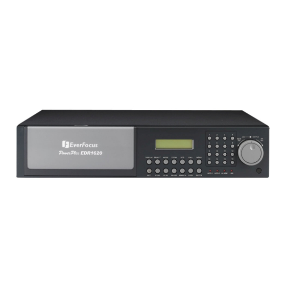
Page 11: Front Panel
Product Overview The EDR1640/1620/920 DVR’s are the industry’s first full-featured digital video recorder designed specifically for use within the CCTV security industry. EDR1640/1620/920 DVR’s incorporates all the benefits of digital video recording, is simple to install, and operates just like a VCR. Highly efficient compression technology and superior resolution of recorded images make the Digital Video Recorder stand out from the competition as the best choice for security surveillance. -
Page 12: Hard Disk
Two Hot-Swappable 3.5” IDE Hard Disk 1640: Up to 480 IPS for NTSC (400 IPS for PAL) Recording Rate 1620/920: Up to 240 IPS for NTSC (200 IPS for PAL) Recording Mode Continuous, Schedule, Event (Motion and Alarm) recording Playback Rate... - Page 13 Operating Temperature Recording Rate 1640 model Half D1 720x240 : 240 IPS 1620 model Half D1 720x240 : 120 IPS 920 model Half D1 720x240 : 120 IPS C ~ +40 C / 3 ~104 NTSC 720x480 : 120 IPS...
-
Page 14: Front Panel Keypads
Front Panel Keypads Keys: 1. REC: Press this key to start instant recording. 2. STOP: Press this key to stop recording and playing back. 3. PLAY: Press this key to start playing back. 4. PAUSE: Press this key to pause the playback picture. 5. - Page 15 9. SELECT: On live view, press this key to assign a camera to a multi-screen or to adjust single screen display properties. In menus, press this key to select certain features. 10. MODE: Switch PIP, 4, 7, 9, 10, 13 and 16 displays in Live and Playback modes.
- Page 16 15 . Shuttle and Jog Dial 16 . System LEDs LEDs for system active HDD, ALARM and LAN display. 17 . Channel Key (1~16) Press channel key (CH1~CH16) to display that channel in full screen view. 18 . HDD LOCK Turn on HDD power and prevent HDD theft.
-
Page 17: Back Panel Connections
Back Panel Connections Main Power plug: power source to AC 100~ 240V. Audio IN: Audio inputs 1~4 for recording, and it can be set to “YES” or “NO” in the RECORD SETUP MENU. Audio OUT: Connect an audio output to a monitor or other device. MAIN MONITOR: This connector is used for the main monitor display, a number of different display modes may be selected for viewing. - Page 18 For EDR920 Series: VIDEO OUT(1~9): Top row BNC connectors for video looping out 1~9. VIDEO IN(1~9): Bottom row BNC connectors for video input 1~9 . Alarm Input ALM-INPUT: Normal open or normal close type alarm signal inputs. The Alarm Input can be selected as normal open (N.O.) or normal close (N.C.) input in the ALARM SETUP MENU.
- Page 19 Connect from Cascade out of the DVR to Cascade In of another with BNC connectors. Repeat the same step for all your DVRs until you connect the last Cascade...
-
Page 20: Monitor Display
Monitor Display The status information of the cameras or machine will show up, and be located at different places on the screen. 1. Channel tag: A channel tag indicates the channel name of the screen. 2. Event sign: Event signals which are small icons with a capital letter and red background show the events on each screen. - Page 21 Temperature indication. This shows if the hard drive’s temperature is overheated. Overheat is determined in HDD TEMPERATURE of WARNING SETUP MENU. Fan fail indication. This shows when the fan fails to work normally. If you get this warning, contact technical support for assistance. 3.
- Page 22 Current date The current date which is set in the TIME/DATE SETUP MENU. Record status Displays current Hard Drive and record position. R01: currently recording on Disk 1 16%: currently recording at 16% of total HD position NOTE: Percentage only indicates the physical point of recording on the Hard Drive, not the total disk space used.
-
Page 23: Installation
Installation The installations described below should be made by qualified service personnel or system installers. Please check accessories in the packaging before beginning installation. Please refer to the following diagram for the basic wiring connections. Note: Monitors and Cameras must be purchased separately. Diagram 2.1 Diagram 2.2 Chapter... -
Page 24: Video Connections, Dvr Cascading
The MAIN monitor may optionally be connected through a Y-C (S-Video) cable to achieve an improved image quality. For local DVR operation, MAIN monitor connection is compulsory. Call and matrix monitors can be connected optionally. ATTENTION: Make sure that there is a video signal on video input 1 upon start-up, as this input is... - Page 25 DVR Cascading The digital video recorders provide "CASCADE IN" and "CASCADE OUT" video connections. In combination with EKB500 keyboard, up to 255 EDR1640/1620/920 can be cascaded and administrated via one single main monitor. Cascading is effected by connecting the DVRs “CASCADE OUT”...
-
Page 26: Audio Connection Installation
Sample installation with audio connection to video cameras providing audio output: Diagram 2.5 The EDR1640/1620/920 DVRs provide 4 audio inputs and 1 audio output. The inputs are designed for max. 500 mV to 10 KOhm line audio signals. ATTENTION: The direct connection of a non-amplified microphone is not supported (a microphone amplifier is required). -
Page 27: Speed Dome Installation
Speed Dome Installation Speed dome or telemetry receiver pan/tilt/zoom control is available through web browser or the optional PowerCon software if the DVR is connected to a network. Local telemetry control is provided by the optional EKB 500 keyboard. Supported protocols: EverFocus, Pelco-D, Pelco-P, ED2200/2250 Diagram 2.6... -
Page 28: Alarm Input / Output Installation
/ receiver itself! (i.e. DVR ID: 2, PTZ ID: 3) Alarm Input / Output Installation The EDR1640/1620/920 alarm inputs can be used for recording start or recording rate adjustment. Furthermore, alarm reactions such as camera switching to monitors, buzzer, e-mail and network alarm are available. - Page 29 Descriptions: ALMINxx: Alarm input xx (1~16) GND: common ground for alarm inputs ALM_COMx: output relay x , contact root ALM_NOx: output relay x , NO contact ALM_NCx: output relay x , NC contact ALMRST: Alarm reset, control input for alarm reset, for dry NO contact towards GND DISKFULL: OC output contact for signal HDD full, switches to GND REC_IN: Control contact for recording start...
- Page 30 SPARE_IN: N.O. Control input for playback function, playback is active as long contact is closed. NO contact alarm input connection: NC contact alarm input connection: Output relay in idle state:...
-
Page 31: Eda800S Installation (Optional)
EDA800s Installation (optional) The EDR1640/1620/920 image storage capacity can be expanded using EDA800s hard disk expansion units. Max. 6 EDA800s with 8 hard disks each can be connected via SCSI bus. Diagram 2.8 For installation details of the EDA-800S hard disk expansion unit, please refer to the EDA800s manual. -
Page 32: Network Connection Through Patch Cable
Note: A HDD should be installed before EDR1640/1620/920 is booted, or the EDR1640/1620/920 will not detect a HDD until you reboot it with a HDD. Please make sure the green HDD indicator light is ON. If the Hard Disk Drive is not locked in with the key the Hard Drive will not being recognized and the DVR will not go into record mode. -
Page 33: Final Install Process
Once you have completed the basic wiring installation and the hard disk drive installation you are ready to turn on the DVR. Simply plug in the power source and turn the switch to the on position. The POWER LED lights will light up if power is normal. Once the system has finished loading, the next... -
Page 34: Dvr Menu Setup
The following chapter will walk you through the detailed DVR Menu step by step and how to set the DVR for your specific application. To begin this process, press the MENU key. Once inside the main menu you will find there are 12 setup option pages as follows. -
Page 35: Time/Date Setup Menu
Jog Dial on the DVR. There are three date formats which are YYYY-MM-DD, MM- DD-YYYY and DD-MM-YYYY to be selected. DATE: This field represents the date on the DVR. To change this, simply use the Jog Dial on the DVR. -
Page 36: Start Time
DAYLIGHT SAVING: This field represents the daylight savings on the DVR. To change this, simply use the Jog Dial on the DVR. Select “ON” or “OFF” to enable or disable daylight saving time function. In order to set a daylight saving time zone, you need to disable daylight saving first. -
Page 37: Time Server
To change this, simply use the Jog Dial on the DVR. 9. TIME SERVER You can set the time server address that the DVR connects to for time synchronize. To find the IP address of NTP Server, please follow these steps: a) Go to a PC that is connected to the internet. - Page 38 Pacific Daylight Time subtract 7 hours from GMT Pacific Standard Time subtract 8 hours from GMT Alaska Daylight Time subtract 8 hours from GMT Alaska Standard Time subtract 9 hours from GMT Hawaii-Aleutian Daylight Time subtract 9 hours from GMT Hawaii-Aleutian Standard Time subtract 10 hours from GMT 11.
-
Page 39: Camera Setup Menu
PTZ ID: Select PTZ ID/Address from 001~255 or OFF. OFF is the same as 000. This ID must match the ID used by the PTZ camera. To change this, simply use the Jog Dial on the DVR. INSTALL/COVERT: For installation of camera, select “ON” to enable a camera, and “OFF”... - Page 40 REC QUALITY: Select an image quality for recording. There are six different qualities available. A higher image quality uses more HDD space. To change this, simply use the Jog Dial on the DVR. The estimated space needed per second lists below: 720x480...
- Page 41 6. REC SPEED & ACTION: TP: Scheduled recording time 1~8 which can be set in the SCHEDULE SETUP MENU. “N” is the normal recording period, which is activated by pressing the Record button. If you have set a Time Period in Schedule Setup Menu, then there will be a star sign (*) beside that TP in Camera Setup Menu.
- Page 42 7. SUMMARY : Dial Jog to change items in the SUMMARY table. All cameras’ statuses are shown in the SUMMARY table. The table is for checking camera overall statuses only, not for setting. Note: The SUMMARY table also exists in ALARM, MOTION and VIDEOLOSS SETUP MENU.
-
Page 43: Record Setup Menu
Record Setup Menu Diagram 3.6 is a screen shot of the RECORD SETUP MENU. This menu is for setting up the options for recording audio and video. In the RECORD SETUP MENU the following fields are defined as follows: RECORD AUDIO: YES: Audio will be recorded when machine is recording and a microphone is present. -
Page 44: Record Mode
Select “YES” to enable pre-alarm recording function. Select “NO” to disable pre-alarm recording function. RELAY OUT By selecting “1”, user can easily identify whether DVR is recording or not if relay output is connected to a signaling device. Select “NONE” if you do not wish to identify recording status. -
Page 45: Alarm Setup Menu
SETUP MENU the following fields are defined: 1. ALARM This field is to turn alarm detection on or off. The default value is ENABLE. To change this, simply use the Jog Dial on the DVR. ENABLE: Enable alarm detection. DISABLE: Disable alarm detection. - Page 46 The Default setting is the same camera number as the current alarm. To change this, simply use the Jog Dial on the DVR. PTZ PRESET Select PTZ PRESET from “001”...
- Page 47 12. CALL MON: Display on a call monitor when an alarm occurs. NO CHANGE: No change on the call monitor display when an alarm occurs. SEQUENCE: Display in sequence mode on call monitor when an alarm occurs, according to sequence duration set in Camera Setup Menu. ACTIVE CAMERA: Display the active camera in full screen mode to the call monitor when an alarm occurs.
-
Page 48: Motion Setup Menu
In the MOTION SETUP MENU the following fields are defined as follows: MOTION This field is to turn motion detection on or off. The default value is DISABLE. To change this, simply use the Jog Dial on the DVR. ENABLE: Enable motion detection. DISABLE: Disable motion detection. - Page 49 This will transmit a signal to another device. The setting of alarms are NONE = not activated, 1 = output signal 1 transmits, 2 = output signal 2 transmits, 3 = output signal 3 transmits and 4 = output signal 4 transmits. To change this, simply use the Jog Dial on the DVR. ALARM EMAIL YES: Send an email when an alarm occurs.
-
Page 50: Motion Area
13. MOTION AREA Enter a desired channel and press SELECT or middle mouse button to edit a motion area. MOTION must be set as “Enable” in order to edit the motion detection area. To quit the motion area edit, press MENU or right-click the mouse to obtain a selection menu, select “EXIT”... -
Page 51: Videoloss Setup Menu
This will transmit a signal to another device. The setting of alarms are NONE = not activated, 1 = output signal 1 transmits, 2 = output signal 2 transmits, 3 = output signal 3 transmits and 4 = output signal 4 transmits. To change this, simply use the Jog Dial on the DVR. Diagram 3.9... -
Page 52: Alarm E-Mail
ALARM EMAIL: Select “YES” for sending an email when Video Loss event occurs. The email address can be set in the NETWORK SETUP MENU. 6. BUZZER: Audible alarm buzzer. ENABLE: To enable a VIDEOLOSS buzzer. DISABLE: To disable a VIDEOLOSS buzzer. 7. -
Page 53: Network Setup Menu
MENU: CONFIG, ALARM, EMAIL, PASSWORD, PPPoE and DDNS. Please refer to the Networking Chapter of this manual to fully understand how to setup your network for this DVR. In the Network Setting Menu the following fields are defined as follows: Note: Since every Network Configuration is different, please contact your Network Administrator or ISP for how to assign those IP addresses and port numbers. -
Page 54: Control:
Refer to Networking Chapter for more details. SUBNET MASK This field is to set the subnet mask for your network so as the DVR will be recognized within the network. Example: 255.255.255.000. To change this, simply use the Jog Dial on the DVR. -
Page 55: Alarm (Network)
DVR. This option cannot be changed. 3.7.2 ALARM (NETWORK) DVR can send out Alarm message to an Alarm Server. This function is reserved to work with our Control Management System – PowerCon4. In the ALARM of the NETWORK SETUP MENU,... -
Page 56: Email
4. SERVER 1: assign the IP address of Alarm server 1. 5. SERVER 2: assign the IP address of Alarm server 2. 6. SERVER 3: assign the IP address of Alarm server 3. 3.7.3 EMAIL In the EMAIL of the NETWORK SETUP MENU, we define: In the EMAIL of the NETWORK SETUP MENU, we define: 1. -
Page 57: Password
Example: In Motion Setup Menu, if the “EMAIL/NETWORK” is set to “YES”, this e-mail address will receive a message and a still image (in “ARV” format) from the DVR when Motion is triggered. This “ARV” file can be played back by opening “DVRViewer.exe” which can be downloaded from the DVR’s Network Viewer or from the Copy Menu. -
Page 58: Pppoe
To change this, press Enter to move to each character and use the Jog Dial on the DVR to change each character. Note that the password is limited to numbers only. There are 3 level types: 1. Admin: User has all the rights including viewing live video, performing a search, playback and controlling the PTZ camera (if one is connected). -
Page 59: Secondary Dns
4. SECONDARY DNS If your ISP provides you with a secondary DNS address, please set it in here. NOTE: Please complete all settings in the PPPoE Setup Menu before changing IP CONFIG to PPPoE in the CONFIG options. If you make this change before completing PPPoE settings, then the PPPoE function will not work. - Page 60 4. RECORD ID Identity tag used by certain DDNS providers 5. FQDN The domain name of this account. NOTE: If using “EverFocusDDNS.com” as the server, there is less information required. For more details on DDNS setup, see the Networking section of the manual.
-
Page 61: Schedule Setup Menu
This field represents the day of the week you wish to set the timer record for. Initially it is set to DLY as default. You may choose from MON-SUN as well as WDAY, WEND, and DLY. To change this, simply use the Jog Dial on the DVR. MON (Monday), TUE (Tuesday), WED (Wednesday), THU (Thursday), FRI (Friday), SAT (Saturday), SUN (Sunday). - Page 62 This field is used to set the time you wish to stop the timer recording. To change this, simply use the Jog Dial on the DVR. Hour: 0 ~ 23 in 24 hour time format; 1~12 in 12 hour time format.
-
Page 63: Disk Setup Menu
Disk Setup Menu Diagram 3.17 is a screen shot of the DISK SETUP MENU. This menu is for viewing Disk information and formatting the disks. For initial setup or major setup changes we recommend formatting the Hard Disk. In the DISK SETUP MENU the following fields are defined as follows: 1. - Page 64 Note: System will ask you to stop recording if you try to delete the disk while still in the record mode. 3. THERMOMETRIC SCALE Select CELSIUS or FAHRENHEIT for thermometric scale of the disk. 4. NO Shows the hard drive number. The number of disks displayed may vary depending on the model. 5.
-
Page 65: Control Setup Menu
This field is to set the stop bit for the RS232 connection. There are two different stop bits, 1 or 2. The default in the DVR is set to 1. To change this, simply use the Jog Dial on the DVR. -
Page 66: Ptz Protocol
RS232/RS485 ID This entry is used to assign each device its own ID code if more than one DVR is used through the RS232/RS485 connection. The default is set to 001. To change this, simply use the Jog Dial on the DVR. -
Page 67: Warning Setup Menu
This will transmit a signal to another device. The setting of alarms are NONE = not activated, 1 = output signal 1 transmits, 2 = output signal 2 transmits, 3 = output signal 3 transmits and 4 = output signal 4 transmits. To change this, simply use the Jog Dial on the DVR. 3. ALARM DURATION Permanent. -
Page 68: Send Email
This will transmit a signal to another device. The setting of alarms are NONE = not activated, 1 = output signal 1 transmits, 2 = output signal 2 transmits, 3 = output signal 3 transmits and 4 = output signal 4 transmits. To change this, simply use the Jog Dial on the DVR. 3. ALARM DURATION Permanent. -
Page 69: Stop Record
4. NETWORK ALARM YES: To enable network alarm. NO: To disable network alarm. 5. SEND EMAIL YES: Send an email when HDD’s temperature is overheated. NO: Will not send an email when HDD’s temperature is overheated. The email settings can be set in the NETWORK SETUP MENU. 6. -
Page 70: No Hdd
This will transmit a signal to another device. The setting of alarms are NONE = not activated, 1 = output signal 1 transmits, 2 = output signal 2 transmits, 3 = output signal 3 transmits and 4 = output signal 4 transmits. To change this, simply use the Jog Dial on the DVR. 3. ALARM DURATION The length of time the buzzer remains active. -
Page 71: Hdd Full
This will transmit a signal to another device. The setting of alarms are NONE = not activated, 1 = output signal 1 transmits, 2 = output signal 2 transmits, 3 = output signal 3 transmits and 4 = output signal 4 transmits. To change this, simply use the Jog Dial on the DVR. 3. ALARM DURATION The length of time the buzzer remains active. - Page 72 4. NETWORK ALARM: YES: To enable network alarm. NO: To disable network alarm. 5. SEND EMAIL: YES: Send an email when HDD is full. NO: Will not send an email when HDD is full. The email settings can be set in the NETWORK SETUP MENU.
-
Page 73: System Setup Menu
“DEFAULT”: restores the factory default values. “LOAD”: uploads saved DVR configuration settings from USB. “SAVE”: saves the current DVR configuration settings to USB device. Note that a USB device must be inserted properly before choosing the “LOAD” or “SAVE” options. System will ask you to stop recording if you try to access any of these options while the system is recording. -
Page 74: Quick Play
4. UPDATE SYSTEM SOFTWARE: Turn the jog to enter the selection window. YES: Press SELECT on YES to update system software from USB. NO: Press SELECT on NO to cancel updating. Note: System will ask you to stop recording if you try to update while system is recording. USB device must be inserted properly before updating system software. - Page 75 8. PASSWORD and RIGHTS: The different login passwords indicate the different level of users; no login name is necessary. Each number will replace the “*” sign when the digit is highlighted. Turn the Jog to change the selected digit of the password; press ENTER to go to next digit and CALL to go to the previous.
-
Page 76: Recording Overview
Record button for recording, much like pressing the record button on a VCR. Scheduled recording (1~8) is based upon a set time period of when to begin & end the recording. Event recording consists of an alarm or motion event triggering the DVR to record on that event. -
Page 77: Schedule Recording Setup
We will now define two event recording types ALARM and MOTION. After the event recording is enabled, the DVR will start an event recording when an event occurs. For instance, when motion activity or alarm action is detected by the DVR it will begin recording at the specific IPS set in the Event column. - Page 78 2. When the event is set, enter the CAMERA SETUP MENU to set the event recording speed (IPS) of the camera in the time period (TP) section. 3. Once the event and record and speed are set, you need to activate Instant Recording or set a time period (TP) in the SCHEDULE SETUP MENU.
-
Page 79: Alarm Input Recording (Input Trigger)
ALARM INPUT RECORDING (Input trigger) DVR provides a record function which is triggered by external signal via the 19th pin of the ALARM INPUT / OUTPUT port. When the record input signal is triggered constantly, DVR will start to record according to the speeds set on Time Period (TP) N. -
Page 80: Playback Overview
Before continuing please be sure to have reviewed DVR Menu Setup (Chapter 3) and Recording Setup (Chapter 4). You are now ready to begin setting up the DVR for playback. This chapter will show you how to setup the recorder for basic playback. -
Page 81: Search Playback
(4) Slow Forward/Reverse Playback During playback mode, press PAUSE key to freeze the playing back picture. Turn the Shuttle dial clockwise to begin slow forward playback. Turn the Shuttle dial counterclockwise to begin slow reverse playback. The speed will show on the status bar of the bottom screen. The available speeds are 1/2, 1/4, 1/8, 1/16, and 1/32. - Page 82 (1) TIME / DATE Search Playback The SEARCH MENU will show up after pressing SEARCH key. Select “BY TIME / DATE”, and then select the start date/time you want to search. Then, select the camera number and Disk Number to be searched. Lastly, press SELECT or the tilt wheel of mouse to start search. Note: If there is no video stored in the date/time specified, then the image will show the end of the last playback, and the display time on the status bar will show “??:??”.
- Page 83 EVENT Search Playback To search by “EVENT”, select “BY EVENT” for Method. Set the Start and End Date/Time limits for the events to be searched. Choose from 7 search filters: ALARM, MOTION, VLOSS, A/M, A/V, M/V and A/M/V The indications of each filter are shown below. EVENT ALARM Search ALARM events...
- Page 84 The event types and number show on the second column of the search list. An: an Alarm event, n = the alarm number. Dn: HDD overheated, n = drive number. Fn: Fan fail, n = 1~3 fan number. LH: (Logical Head): beginning of recording (earliest recorded date) LUn: Local User login, n = 1~3;...
-
Page 85: Copying Video
Before continuing please be sure to have reviewed the preceding chapters. You are now ready to copy an image or video from the DVR. This chapter will show you how to copy a still image or movie from the recorder. - Page 86 3. CAMERA NO Camera channel number. You can select an individual camera or ALL cameras. If you select ALL cameras while you are recording, DVR will stop recording temporarily, until copy process is terminated. 4. START DATE & TIME: The start time of video you want to copy.
-
Page 87: Viewing A Copied File
After choosing copy settings, press SELECT or the tilt wheel of the mouse to begin copy. 1. Every 30-minutes of data will be saved as one file. However, if this file size exceeds 2G, DVR will automatically split it into smaller video clips that will be copied individually. The current segment and completion percentage are displayed at the bottom of the screen. -
Page 88: Call Overview
Call Overview This chapter will give you basic details on how to setup the CALL MENU on the DVR. Press the CALL key and the CALL MENU will pop up as below. In CALL MENU, you can do the following settings for the selected monitor: 1. - Page 89 Diagram 7.2 Dial jog to set sequence dwell time for each camera on matrix monitor 1~4. Sequence dwell time can be set from 00 to 99 seconds. Press Enter/Call key to go next/previous selection.
-
Page 90: Screen Display Setting & Mode
8. Screen Display Setting & Mode In a full screen display, press SELECT key to pop up the display adjustment window as below: In the screen display setting menu, we define: CAMERA: The current camera. (cannot be changed) BRIGHTNESS: The brightness percentage of the current camera; from 0% to 100%. CONTRAST: The contrast percentage of the current camera;... - Page 91 When SHARPNESS is OFF, the image becomes blurred in an indoor environment. However, this setting is suitable for outdoor use. If image flickers from a bright, outdoor environment, this can be reduced by turning SHARPNESS OFF. The selected item will show in red color bar. Use Jog to increase or decrease the value. Press ENTER to confirm the setting value and move to next item.
-
Page 92: Mode Button
Mode Button Press MODE to switch 4, 7, 9, 10, 13, 16 and PIP (picture in picture) displays for Live and Playback mode. -
Page 93: Firmware Upgrade
Copy the .ETW file to your USB pocket drive from your computer. Insert the USB pocket drive in to the top USB slot on the front panel of the DVR. When inserting the USB, make sure the direction of insertion is correct. -
Page 94: Networking Overview
10. Networking Overview This chapter will try to give you a detailed instruction on how to network the DVR. Before we begin the process of networking your digital recorder we should have a working knowledge of what a network is and how it works. This will be a helpful in completing the networking process. -
Page 95: Virtual Ports
10.5 Pre-Installation Before we begin with the installation we must ask ourselves a few questions in order to figure out where to begin with networking our DVR’s. Do you have Hi-speed Internet? There are many types of high speed Internet available. Three commonly used ones are T1, Cable, and DSL (in order of speed). - Page 96 That way, you can host a website, email server, or other type of server connection. Everfocus suggest using a static IP address. If your Internet provider does not offer a static IP address you have the option to use a dynamic IP address.
-
Page 97: What Type Of Network Connection Do You Have
10.6 What Type of Network Connection do you have? Everfocus DVR’s can operate using three distinct types of networking connections. 1. Simple One to One Connection: A simple one to one connection is the most simple network connection. Basically it is a connection between a Computer and Another Computer or in this case a DVR using a cross-over cable. - Page 98 Once you have a cross over cable plug one end into the LAN port on the back of the recorder and the other into the network card on the back of the computer. Now Log into the Everfocus DVR menu and using the jog dial from the previous chapter go to the Network Setting Menu.
- Page 102 Once you have reached this point click ok and restart both the computer and the digital recorder. To access the DVR from the computer simply open Internet Explorer and in the address bar type: http://192.168.1.3...
- Page 103 Such is the case for the DVR.. The EDR series of recorders require that ActiveX be enabled on Internet Explorer in order to fully view the cameras. If the ActiveX options on Internet Explorer are not on, then the cameras will not be displayed.
- Page 105 Once in CUSTOM LEVEL, Scroll down to ACTIVEX CONTROLS AND If you are still not able to load the active X control, change RESET CUSTOM SETTINGS to low and then click on RESET. Once Enabled, Click on OK on the Security Settings window. Then click on apply on the Internet Options window and finally click OK.
-
Page 106: Direct High Speed Modem Connection
10.8 Direct High Speed Modem Connection Internet Straight Through Ethernet Cable Pin outs: The Diagram below shows the pin configurations for a straight cable. Connection Procedure: The First step is to purchase or make a straight through cable. We recommend purchasing one if you have never made a straight through cable. - Page 107 Now Log into the Everfocus DVR menu and using the jog dial from the previous chapter go to the Network Setting Menu. Assign the Static IP address which you obtained from the internet service provider to the DVR, the Subnet mask from the internet service provider to the DVR, and the default gateway of the internet service provider.
-
Page 108: Router Or Lan Connection
10.9 Router or LAN Connection Internet Cat 5 Straight Through Cable Straight Through Ethernet Cable Pin outs: The Diagram below shows the pin configurations for a straight cable. Connection Procedure: The First step is to purchase or make a straight through cable. We recommend purchasing one if you have never made a straight through cable. - Page 109 Once you have a straight through cable plug one end into the LAN port on the back of the recorder and the other into the router. Now Log into the Everfocus DVR menu and using the jog dial from the previous chapter go to the Network Setting Menu.
- Page 110 DVR through the DVR’s Network Menu Setup. Note: If you wish to have multiple users log into the DVR please open a range for the control and data ports on your router. For example if you would only like 4...
-
Page 111: Linksys Port Forwarding
Chapter 11. Linksys Port Forwarding This chapter will cover a few simple configurations for the Linksys router. Please understand we do not support this product and will not give tech support on it. If you need Technical support on this router you must call Linksys. This Chapter is to offer some help to the installer and end user nothing more. - Page 112 The Applications and Gaming Tab allows you to set up public services on your network, such as web servers, ftp servers, e-mail servers, or other specialized Internet applications. (Specialized Internet applications are any applications that use Internet access to perform functions such as videoconferencing or online gaming.
- Page 113 Application - In this field, enter the name you wish to give the application. Each name can be up to 12 characters. Start/End - This is the port range. Enter the number that starts the port range under Start and the number that ends the range under End. Protocol - Enter the protocol used for this application, either TCP or UDP, or Both.
- Page 114 Note: If you wish to have multiple users log into the DVR please open a range for the control and data ports on your router. For example if you would only like 4...
-
Page 115: D-Link Port Forwarding
Chapter 12. D-Link Port Forwarding This chapter will cover a few simple configurations for the D-Link router. Please understand we do not support this product and will not give tech support on it. If you need Technical support on this router you must call D-Link. This Chapter is to offer some help to the installer and end user nothing more. - Page 116 Example: Firewall - Select Enabled or Disabled Name - Enter the name referencing the virtual service Action – Either Allow or Disallow its use. Source - The server computer in the WAN (Wide Area Network) that will be providing the virtual services.
- Page 117 Note: If you wish to have multiple users log into the DVR please open a range for the control and data ports on your router. For example if you would only like 4 clients to connect to the DVR open 1600-1603 and 37260 ~ 37263 If your Internet Service Provider Blocks port 80.
-
Page 118: Everfocus Ddns Setup
Set up the Network Menu according to the instructions detailed in the Networking chapter. Go to the website http://everfocusddns.com and check for an available name. In DVR’s Network Menu, go to DDNS. Choose “everfocusddns.com” for the Server and put in your chosen name for DVR Name. - Page 119 Press the Select button to synchronize the DVR with the DDNS server. You should see the word “Success” at the bottom of the screen. If you see “Could Not Find Server” instead, double check your network settings until you get “Success”.
-
Page 120: Viewing Through Internet Explorer
14. Viewing through Internet Explorer To access the DVR from a computer simply open Internet Explorer and in the address bar type: http:// (LAN or IP address of your internet service provider) The digital video login page will appear on the screen similar to the one shown above. - Page 121 Installing ActiveX controls...
- Page 123 Enabling ActiveX Controls Note: This section is only necessary if you DO NOT see the yellow ActiveX bar at the top of your browser screen.
- Page 126 The above diagram is the main screen display. The icons on the lower corner of the screen are mainly for control and configuration; those on the right side are for status indication. If any icon is grayed, it means that the specific function is not accessible in the current mode. The followings are a brief description for each of the icons.
- Page 127 7. There are two methods of searching past video: by Event and by Time. 8. Types of events to be searched: Alarm, Motion and/or Vloss. 9. All available events are shown in the list. Click the desired event to highlight it. 10.
- Page 128 21. Record: Press the button to remotely activate the DVR’s record function. Press again to stop recording. 22. Audio: This function allows you to transmit audio from DVR to your PC’s remote site.
-
Page 129: Search
14.1 Search 14.1.1 Search by TIME There are 3 ways to do search by time. Press 1. Press the M button to change the Month to be searched, D for day, h for hour, m for minute and s for second. The buttons on the left-hand side are to decrease the value, whereas those on the right-hand side are to increase the value. -
Page 130: Search By Event
14.1.2 Search by EVENT 1. Select Event Type from Alarm, Motion and Vloss. Note: Please keep at least one event type checked. 2. Select the Disk No. from which you would like to search events. 3. Press Update button to refresh the event list. 4. -
Page 131: Ptz Control
14.2 PTZ control 1. Select the PTZ camera from drop-down menu. 2. Select Action Mode you want to use. There are 4 options available: Continuous, Step x10, Step x5 and Step x1. 3. Use Direction Arrows (up, down, left, right) to move/adjust the focus to your desired direction and angle. -
Page 132: Remote Archive
14.3 Remote Archive To Archive files: 1. Select Disk No.: The hard drive you want to archive from 2. Disk Storage Time: Start Time/End Time indicates the start and end time of the selected disk 3. Camera: Select the camera that you wish to archive from. 4. - Page 133 2) Move the slide bar between the buttons to change Month, Day, Hour, Minute, and second to be searched. Move the slide bar to the left to decrease the value, or to the right to increase the value. 3) Enter Month, Day, Hour, Minute, and second directly in display bar. 4) Press OK to select time.
- Page 134 2. Select “Run” or “Save” the file. 3. Open the DVRViewer.exe for loading the archived EDR MPEG4 Files (.arv)
- Page 135 Detailed explanation of DVRViewer is as follows: Load File: to load the archived EDR MPEG4 Files (.arv). Stop: to stop playing video. iii. Play: to play video. <<Step: step backward after pausing. Pause: to pause playing. Step>>: step forward after pausing. vii.
-
Page 136: Remote Configuration
14.4 Remote Configuration Click on the “CONFIG” tab to open a page where you can remotely change the DVR’s settings. Click on each option to go to the settings for that page. When you finish making changes on a screen, press Apply to save the settings. - Page 137 DATE/TIME setup menu Set Date/Time Manually 1. Click on the calendar button to set Date/Time manually. A calendar will show up as shown below. 2. Click “<<” to decrease Year value, “>>” to increase Year value. 3. Click “<” to decrease Month value, “>” to increase Month value. 4.
- Page 138 CAMERA setup menu RECORD setup menu ALARM setup menu...
- Page 139 MOTION setup menu Set Motion Grid 1. Non-green squares are disabled for motion; green squares are enabled. 2. Click and hold the mouse to begin selecting squares in the motion grid. 3. Drag the mouse to highlight the desired area. 4.
- Page 140 NETWORK 1 setup menu The Network Configuration Settings can not be changed remotely. These must be changed in the DVR’s Network Menu. NETWORK 2 setup menu After saving changes to the account, password, or level, the changes will take effect the...
- Page 141 SCHEDULE setup menu CONTROL setup menu...
- Page 142 2. Find the folder where the firmware upgrade is saved and choose Open. 3. On the DVR’s monitor, you will see a notice that the firmware is being updated. Note: DO NOT try to open the menu or make changes at the DVR while this process is happening.
-
Page 143: Interface Specifications
Interface Specifications RS485 This Digital Video Recorder may be controlled by a computer or control keyboard (EKB500) via the RS485 interface. Pin definition of RS-485 connector on DVR back panel is shown in the following picture. 15.1 Transmission Setting There are 6 different speeds that can be used to transmit instruction or information through the RS485 port on the device, 1200 baud, 2400 baud, 4800 baud, 9600 baud, 19200 baud, and 3840 baud. -
Page 144: Remote Control Protocol
15.2 Remote Control Protocol A computer can be used to control the DVR by sending the packet as follows. ========================================================= EDR1640/1620/920 485 Control Code Protocol ========================================================= 1-1. Sample control code packets Example1: A packet that send "REC" key to EDR(ID=5) - Page 145 0x4B (OPcode = key ) 0x0B (DATA1 = "Play" keycode ) 0x59 (checksum) 2-1. The format of message packet is as follows: Length Byte (Prefix: 0x86, 0x87, or 0x88 ... ) Receiver ID high byte Receiver ID low byte Opcode Byte Data Byte1 Data Byte2 Data Byte3...
- Page 146 0000000 0000001 0000000 0000010 0000000 1111110 0000000 1111111 0000001 0000000 0000001 0000001 0000001 1111111 0000010 0000000 0000011 1111111 16382 1111111 1111110 ---------------------------------------------------------- 2). Broadcast ID ---------------------------------------------------------- Decimal 14bit binary value Hbyte Lbyte Receiver ID ------- ------------------- ------ ----- ----------- 16383 1111111 1111111 ---------------------------------------------------------- 2-4.
- Page 147 ------ ------ -------------------------- 0x4B Keycode A remote key pressed ------------------------------------------ 2-4-1. A remote key pressed (OPcode=0x4B) ------------------------------- Data1 Key ------ ----------------------- 0x00 CH1 0x01 CH2 0x02 CH3 0x03 CH4 0x04 MODE 0x05 ZOOM 0x06 SEQ 0x07 MENU 0x08 REC 0x09 REV.PLAY 0x0A STOP 0x0B PLAY 0x0C PAUSE...
- Page 148 0x1f JOG> 0x20 CH5 0x21 CH6 0x22 CH7 0x23 CH8 0x24 CH9 0x25 CH 10 0x26 CH 11 0x27 CH 12 0x28 CH 13 ------------------------------- 2-5. Checksum Byte Checksum is computed as the sum of all previous bytes (including the length byte), then mask with 0x7f. 0x2c SELECT 0x2d CALL 0x2e ENTER...
-
Page 149: Appendix A: Remote Control
The remote controller (RC200, Diagram A1) is an accessory to enhance the handy operations of the DVR. You can perform all the settings and operations by the remote controller. The effective distances are up to10 meters without any obstacle. The keypad functions are same as... -
Page 150: Appendix B: Mouse Installation
Appendix B: Mouse Installation To use a PS2 mouse with the DVR simply turn off the DVR first. Then plug in a PS2 Optical mouse with Scroll Wheel to the PS2 Mouse port on the back of the DVR. When you power the DVR back up the mouse will have been loaded and you will see a mouse curser on your screen. - Page 151 option a new menu will appear. For example Diagram B2 shows an example of a new menu once you have clicked ok for the menu. Diagram B2...
- Page 152 From this menu you can left click on any one of the menu to select that menu. Diagram B3 To go back to your main screen from here simply click on the Back arrow located on the top right hand of this screen.
-
Page 153: Appendix C:alarm Board Configuration
Appendix Appendix C:Alarm Board Configuration... -
Page 154: Appendix D: Lapse Mode Recording Table
Appendix D: Lapse Mode Recording Table Unit: NTSC Hour Recording LOWER Speed simple complex simple complex simple complex simple complex simple complex simple complex (IPS) 8.04 12.33 8.42 71.98 46.93 68.73 89.97 58.67 85.91 70.40 103.09 88.00 128.87 179.9 117.34 171.82 269.9 176.00... - Page 155 Unit: NTSC Hour Recording LOWER Speed simple complex simple complex simple complex simple complex simple complex simple complex (IPS) 3.53 7.82 3.87 81.97 37.00 74.77 55.50 112.15 163.9 74.00 149.54 204.9 92.50 186.92 245.9 111.00 224.30 103.83 206.19 307.4 138.76 280.38 129.79 257.74 121.92 220.54 113.74 193.07 106.69 169.28 409.8 185.01 373.84 173.06 343.65 162.56 294.06 151.65 257.43 142.26 225.70 112.24 614.8 277.51 560.76 259.59 515.47 243.84 441.09 227.48 386.15 213.39 338.56 168.36 1230...
- Page 156 5.46 2.38 35.65 88.13 31.80 72.95 44.56 110.16 39.75 91.18 59.42 146.88 52.99 121.58 89.12 220.32 79.49 182.36 EDR1620/920 – D1 model HIGH SUPERIOR 6.51 2.67 7.08 3.63 22.22 54.19 20.43 39.86 33.34 81.28 30.65 59.78 44.45 108.37 40.87 79.71 53.34...
- Page 157 Unit: NTSC Hour Recording LOWER Speed simple complex simple complex simple complex simple complex simple complex simple complex (IPS) 8.04 12.33 8.42 93.87 137.46 179.9 117.34 171.82 269.9 176.00 257.74 539.8 352.01 515.47 Unit: Hour Recording LOWER Speed simple complex simple complex simple complex simple complex simple complex simple complex (IPS) 8.04 12.33...
- Page 158 409.8 185.01 373.84 173.06 343.65 162.56 294.06 151.65 257.43 142.26 225.70 112.24 614.8 277.51 560.76 259.59 515.47 243.84 441.09 227.48 386.15 213.39 338.56 168.36 1230 555.02 1121.52 519.17 1030.94 487.67 882.17 454.96 772.29 426.77 677.11 336.72 EDR1620/920 – Half D1 model PICTURE QUALITY (KB) BASIC STANDARD 8.36...
- Page 159 317.27 773.67 297.08 734.40 264.97 607.88 222.24 541.86 204.34 398.56 160.39 1233 475.91 1160.50 445.61 1101.59 397.46 911.82 333.35 812.79 306.52 597.83 240.59 2466 951.82 2321.00 891.23 2203.19 794.92 1823.65 666.71 1625.57 613.03 1195.67 481.18 EDR1620/920 – CIF model PICTURE QUALITY (KB) BASIC STANDARD 4.87 1.97...
- Page 160 Note: The above recording tables are calculated based on 250 GB of system storage. The HDD size required in your DVR may vary from this calculated test result under some conditions. Total storage capacity may vary depending on complexity of video scenes, DVR specifications and features used on the actual installation sites.
-
Page 161: Troubleshooting
The next step is to verify the recorder is getting the correct amount of power. There is no display coming from one of the channels on the DVR? The first step is to verify is the problem coming from the recorder or the camera. - Page 162 415 Oser Avenue Unit S Hauppauge, NY 11788 TEL: 631-436-5070 : 631-436-5027 www.everfocus.com Your EverFocus product is designed and manufactured with high quality materials and components which can be recycled and reused. This symbol means that electrical and electronic equipment, at their end-of- life, should be disposed of separately from your household waste.
Need help?
Do you have a question about the 920 and is the answer not in the manual?
Questions and answers