
Related Manuals for Owon HDS272S


Summary of Contents for Owon HDS272S
- Page 1 HDS200 Dual Channel Series Handheld Oscilloscope User Manual ◼ HDS272(S) ◼ HDS242(S) ◼ HDS2102(S) For product support, visit:www.owon.com.hk/download...
- Page 2 LILLIPUT Company. Fujian LILLIPUT Optoelectronics Technology Co., Ltd. No. 19, Heming Road Lantian Industrial Zone, Zhangzhou 363005 P.R. China Tel: +86-596-2130430 Fax: +86-596-2109272 Web: www.owon.com E-mail: info@owon.com.cn...
- Page 3 General Warranty We warrants that the product will be free from defects in materials and workmanship for a period of 3 years from the date of purchase of the product by the original purchaser from the our Company. The warranty period for accessories such as probes, adapter is 12 months.
-
Page 4: Table Of Contents
Table of Contents SAFETY INFORMATION · · · · · · · · · · · · · · · · · · · · · · · · · · · · · · · · · · · 3 HOW TO IMPLEMENT THE GENERAL INSPECTION HOW TO USE THE OSCILLOSCOPE ·... - Page 5 Multimeter · · · · · · · · · · · · · · · · · · · · · · · · · · · · · · · · · · · · · · · · · · · · · · · · · · · · · · · · · · · · · · · · · · · · · · · · · · · · · · · · · · · · · · · · · · · · · · · · · · · · · 35 Arbitrary Waveform Generator (Optional) ·...
-
Page 6: Safety Information
1. Safety Information (Before using this product, please read the safety information in advance) Safety Terms Terms in this manual (The following terms may appear in this manual): Warning: Warning indicates conditions or practices that could result in injury or loss of life. Caution: Caution indicates the conditions or practices that could result in damage to this product or other property. - Page 7 Warning: To prevent electric shock or fire, use a suitable power adapter. Only power adapters that are dedicated to this product and approved for use in the country of use may be used. Warning: The two channels of the oscilloscope are non-isolated channels. Note that the channel should use a common reference when measuring, and the ground wires of the two probes cannot be connected to two non-isolated places with different DC electrical levels, otherwise it may cause a short circuit due to the...
- Page 8 powered computer through the port, it is not allowed to measure the primary power supply of power grid. Warning: If the input port of the oscilloscope is connected to a voltage with a peak value higher than 42V (30vrms) or a circuit with a peak value of more than 4800 VA, the following measures shall be taken to avoid electric shock or fire: ⚫...
-
Page 9: How To Implement The General Inspection
refers to the level. Level II is the low voltage and high energy level, which refers to the local electrical level applicable to electrical appliances and portable equipment. ◼ Only a qualified person should perform internal maintenance. ◼ Check all Terminal Ratings. To avoid fire or shock hazard, check all ratings and markings on this product. -
Page 10: How To Use The Oscilloscope
instrument can not work normally, or fails in the performance test, please get in touch with our distributor responsible for this business or our local offices. If there is damage to the instrument caused by the transportation, please keep the package. With the transportation department or our distributor responsible for this business informed about it, a repairing or replacement of the instrument will be arranged by us. - Page 11 Description: 1. CH1 and CH2 input connectors. 2. Waveform generator output connector (optional). 3. Display area. 4. The F1 - F4 keys are multi-function keys. In each menu mode, press the corresponding key to select the corresponding menu item. 5. After pressing the HOR key, through the key , you can change the horizontal time base setting, and observe the change of the state information caused by it;...
-
Page 12: Side Panel
15. Enter the system settings key. 16. Switch key for working state of oscilloscope and multimeter. 17. CH1 / CH2 - channel switch key. Side Panel Description: 1. Probe compensation: 3.3V/1kHz square wave signal output 2. Charging or USB communication interface 3. -
Page 13: Introduction To The User Interface Of The Oscilloscope
Introduction to the User Interface of the Oscilloscope 1 2 3 Figure 5: Oscilloscope Interface Description: 1. The trigger status indicates the following information: Auto: Automatic mode. The waveform is being collected without triggering. Trig: A trigger has been detected and post trigger information is being collected. -
Page 14: Functional Check
8. Battery power and external power supply indication. 9. Channel 1 waveform. 10. The pointer indicates the trigger electrical level position of the channel. 11. Channel 2 waveform. 12. The icon indicates trigger-related information, including trigger channel, coupling mode, trigger type and trigger electrical level. For details, please refer to P18 Trigger System. -
Page 15: Probe Compensation
2. The switch on the oscilloscope probe is set to 10X and connected with the CH1 channel. Align the slot on the probe with the plug on the bayonet nut connector (BNC) of the CH1 connector and insert it, then turn the probe to the right and tighten it. Connect the probe tip and ground clamp to the connector of the probe compensator. -
Page 16: Probe Attenuation Coefficient Setting
compensator, and connect the reference wire clamp to the ground wire connector of the probe compensator, and then press the Auto key on the front panel. 2. Check the displayed waveform and adjust the probe until the compensation is correct. See Figure 0-2 and Figure 0-3. Overcompensation Correct compensation... -
Page 17: Safe Use Of Probe
Note: The preset setting of the probe attenuation coefficient in the menu when the oscilloscope is delivered is 10X. Make sure that the attenuation switch setting value on the probe is the same as the probe attenuation coefficient option in the oscilloscope menu. -
Page 18: Vertical System
Warning: To prevent electric shock when using the probe, please keep your fingers behind the safety ring on the probe body. To prevent electric shock when using the probe, do not touch the metal part of the probe head when the probe is connected to a voltage source. -
Page 19: Horizontal System
The normal sampling method uses the AC and DC components of the input signal. Coupling Block the DC component of the input signal. Ground Disconnect the input signal. Choose one of the values according to the probe Probe attenuation factor to keep the vertical scale 100X reading accurate. -
Page 20: Measuring System
Return to the previous menu. Measuring System Automatic Measurement Press and the F1 key to realize automatic measurement. There are 7 types of measurement, and up to 6 types of measurement can be displayed at the bottom left of the screen. Auto range includes frequency, period, amplitude, maximum, minimum, peak-to-peak value, and average value. - Page 21 Time Select to display the time measurement cursor and menu. None Turn off the cursor measurement. When the type is selected as CH1 or CH2, press the arrow keys to move the cursor line A; when the type is selected as Time, press the arrow keys to move the cursor line a.
- Page 22 the input signal, that is, trigger on the rising and falling edges of the input signal. Entering the edge trigging, the trigger setting information is displayed at the bottom right corner of the screen, e.g. . It indicates that the trigger type is rising edge, the trigger source is CH1, the trigger coupling is DC, and the trigger electrical level is -20.0mV.
- Page 23 Save Settings Press the Save key to enter the save function menu. By operating the save function menu, oscilloscope settings, reference waveforms, and files can be stored. ⚫ Settings Any setting can be saved inside the oscilloscope, and restore settings can also be called.
- Page 24 address, the waveform will be displayed, and the address number and waveform related information will be displayed in the upper left corner; if the current address is not stored, it will display "Address No.: No waveform saved". Save the reference waveform of the source to th Save e memory.
- Page 25 Function Description Setting Menu Set the screen backlight to increase in a 10% Luminance 10% - 100% cycle. Backlight Set the screen backlight luminance time. time 120s Unlimited means always on. Unlimited Menu time Set the menu display time. Elapsed 00h:00m Display how long it has been powered on.
-
Page 26: How To Use The Multimeter
otherwise press the return key". If you need to perform the default setting, press F3 again to complete the default setting, otherwise, press the return key. ⚫ USB Connection Press the System key to enter the system setting menu. Select F4 to enter the next page. -
Page 27: Instrument Interface
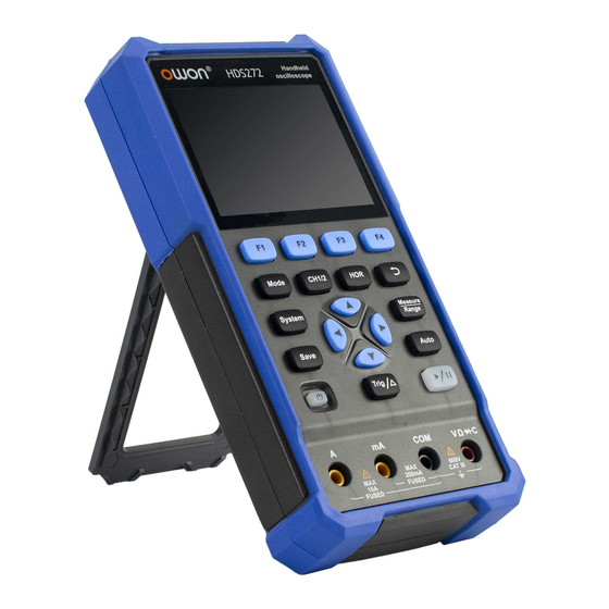
Instrument Interface The multimeter uses four 4-mm safety banana plug input ends: A, mA, COM, Multimeter interface: Multimeter Interface Description: 1. Measurement type indication: ------ DC voltage measurement ~ ACV ------ AC voltage measurement ------ DC current measurement ~ ACA ------ AC current measurement Resist... - Page 28 Cont ------ On/Off measurement ------ Capacitance measurement 2.Range indication: Manual means manual range; Auto means automatic range. 3. Current measurement range. 4. Indicating that there is a USB cable inserted. 5. Battery power indication. 6. “Hold” can keep the current reading on the display. 7.
-
Page 29: Optional
5. How to Use the Waveform Generator(optional) The instrument can provide 4 basic waveforms, sine wave, square wave, ramp wave, pulse wave, and 8 arbitrary waveforms. Connect the output Press the Mode button to switch the instrument interface to the waveform generator function interface. -
Page 30: Output The Sine Waveform
is 50Ω). Note: To change the load value, after selecting *Ω, press direction key to move the cursor left and right; press direction key to change the value. The load range is 1 Ω - 10 kΩ. Output the sine waveform The sine waveform setting menu includes: Frequency/Period, Amplitude/High Level, Offset/Low Level. -
Page 31: Output The Square Waveform
Output the square waveform Press the F1 key to enter the square waveform setting interface. The square waveform setting menu includes: Frequency/Period, Start Phase, Amplitude/High Level, Offset/Low Level. For the setting frequency/period, amplitude/high level, offset/low level, please refer to Output the sine waveform on page 27. Output the ramp waveform Press the F1 key to enter the ramp waveform setting interface. -
Page 32: Output The Arbitrary Waveform
column. Press F2 to switch between Rise Time / Fall Time. Output the Arbitrary waveform Press the F1 key to enter the arbitrary waveform setting interface. arbitrary waveform setting menu includes: Frequency/Period, Amplitude/High Level, Offset/Low Level, Type. For the setting frequency/period, amplitude/high level, offset/low level, please refer to Output the sine waveform on page 27. -
Page 33: Communication With Pc
6. Communication with PC The oscilloscope supports communications with a PC through USB. You can use the Oscilloscope communication software to store, analyze, display the data and remote control. To learn about how to operate the software, you can push F1 in the software to open the help document. -
Page 34: Troubleshooting
7. Troubleshooting 1. The oscilloscope cannot be turned on. It may be that the battery is completely exhausted. At this time, even if the oscilloscope is powered by the power adapter, the oscilloscope cannot be turned on. You need to charge the battery first, and do not turn on the oscilloscope. - Page 35 RUN/STOP. Check whether the trigger mode of the trigger mode menu is normal or single, and the trigger electrical level is out of the waveform range. If so, center the trigger electrical level or set the trigger mode to automatic. In addition, you can press Auto to automatically complete the above settings.
-
Page 36: Technical Specifications
8. Technical Specifications Unless otherwise stated, all technical specifications are applicable to the probe with the attenuation switch set to 10X and this series of oscilloscopes. The oscilloscope must first meet the following two conditions to meet these specifications and standards: ■... - Page 37 Characteristics Description Waveform (Sinx)/x interpolation HDS242(S) 5ns/div - 1000s/div,Stepping Sweep speed range HDS272(S) in the 1-2-5 way 2ns/div - 1000s/div,Stepping (S/div) HDS2102(S) in the 1-2-5 way Time base accuracy ±100 ppm Record length 8K or 4K optional Sensitivity 10 mV/div~10 V/div (Volt/div) range Displacement range ±6 div...
-
Page 38: Multimeter
Characteristics Description According to Record length and time Trigger displacement base Edge trigging Slope Rising edge, falling edge The output of the probe compensator: Characteristics Description Output voltage 3.3Vpp, High-Z (typical) Frequency Square wave 1 kHz (±1%) (typical) Multimeter Characteristics Description Digital display 20,000 readings... -
Page 39: Arbitrary Waveform Generator (Optional)
Basic Minimum Range Accuracy function resolution 200.00mA 0.01mA ±(1%+10dig) 10.000A ± (2.8%+10dig) frequency range:40Hz-1000Hz AC current Overload protection: mA function: self-healing fuse 400 mA/250 V; Ampere functio n: 10A/600 V, D5.2*20, fast-acting fuse 0.01Ω 200.00Ω ±(0.8%+10dig) 2.0000kΩ 0.1Ω ±(0.8%+5dig) 1Ω 20.000kΩ... - Page 40 ±(2.5V – Amplitude Vpp/2) DC offset(High Z) Frequency Resolution 0.01% Channel Waveform Depth Vertical Resolution 14 bit 50 Ω Output Impedance...
-
Page 41: General Technical Specifications
General Technical Specifications Display: Characteristics Description Display type 3.5-inch color LCD display Display resolution 320 horizontal × 240 vertical pixels Display color 65536 colors Display Contrast Adjustable Power supply: Characteristics Description 100 - 240 VACRMS, 50/60 Hz, CAT Ⅱ Power supply DC INPUT: 5VDC, 2A Power <5 W... -
Page 42: Appendix
⚫ 1 USB cable ⚫ 1 passive probes ⚫ 1 crocodile clip cable (HDS242/HDS272/HDS2102) ⚫ 2 crocodile clip cable (HDS242S/HDS272S/HDS2102S) ⚫ 1 set of multimeter probes (one red and one black) ⚫ 1 user manual ⚫ 1 probe correction adjustment knife... - Page 43 Do not use any abrasive chemical cleaning agent to avoid damaging the instrument or probe. Warning: Please make sure the instrument is dry before re-energizing to avoid electrical short circuit or personal injury caused by moisture. Charging and Replacement of Battery During the long-term storage of the device, the battery may be too low due to the self-discharge of the lithium battery and the device cannot be turned on.
- Page 44 the power socket through the USB data cable and power adapter delivered with the machine for charging. Charge the oscilloscope through the USB interface: Connect the oscilloscope to a computer or other equipment through a USB data cable for charging (pay attention to the load capacity of the power supply equipment to avoid abnormal operation of the equipment).
Need help?
Do you have a question about the HDS272S and is the answer not in the manual?
Questions and answers