Table of Contents
Advertisement
HDS200 Dual Channel Series
Handheld Oscilloscope User Manual
HDS25(S)
HDS242(S)
HDS272(S)
HDS2102(S)
HDS2202(S)
For product support, visit:www.owon.com.hk/download
※:The illustrations, interface, icons and characters in the user manual may be slightly
different from the actual product. Please refer to the actual product.
Advertisement
Table of Contents

Related Manuals for Owon HDS25


Summary of Contents for Owon HDS25
- Page 1 Handheld Oscilloscope User Manual HDS25(S) HDS242(S) HDS272(S) HDS2102(S) HDS2202(S) For product support, visit:www.owon.com.hk/download ※:The illustrations, interface, icons and characters in the user manual may be slightly different from the actual product. Please refer to the actual product.
- Page 2 LILLIPUT Company. Fujian LILLIPUT Optoelectronics Technology Co., Ltd. No. 19, Heming Road Lantian Industrial Zone, Zhangzhou 363005 P.R. China Tel: +86-596-2130430 Fax: +86-596-2109272 Web: www.owon.com.cn E-mail: info@owon.com.cn...
-
Page 3: General Warranty
General Warranty We warrant that the product will be free from defects in materials and workmanship for a period of 3 years from the date of purchase of the product by the original purchaser from the our Company. The warranty period for accessories such as probes, adapter is 12 months. -
Page 4: Table Of Contents
Table of Contents 1. Safety Information ..................1 Safety Terms and Symbols ........................ 1 Safety Requirements ........................... 1 2. How to Implement the General Inspection ..........5 3. How to Use the Oscilloscope ..............6 The Structure of the Oscilloscope ....................6 Front Panel and Keys ........................6 Side Panel ............................8 Introduction to the User Interface of the Oscilloscope .............. - Page 5 9. Appendix ....................40 Appendix A: List of Accessories ....................40 Appendix B: Maintenance and Cleaning ..................40 General maintenance ........................40 Charging and Replacement of Battery ..................41 Replacement of Lithium Battery ..................... 42...
-
Page 6: Safety Information
1. Safety Information (Before using this product, please read the safety information in advance) Safety Terms and Symbols Terms in this manual The following terms may appear in this manual: Warning: Warning indicates conditions or practices that could result in injury or loss of life. Caution: Caution indicates the conditions or practices that could result in damage to this product or other property. - Page 7 prevent damage to this product or any other products connected to it. In order to avoid possible hazards, this product can only be used within the specified range. Only a qualified person should perform internal maintenance. Check all Terminal Ratings. To avoid fire or shock hazard, check all ratings and markings on this product.
- Page 8 Schematic diagram of the internal ground wire connection of the oscilloscope: Schematic diagram of internal ground connection when oscilloscope is connected with computer through the port: When the oscilloscope is AC powered by adapter or connected with AC powered computer through the port, it is not allowed to measure the primary power supply of power grid.
- Page 9 Do not use an input voltage higher than the rated value of the instrument. Pay special attention when using 1:1 test wires, because the probe voltage will be directly transmitted to the oscilloscope. Do not touch the bare metal BNC or banana plug. ...
-
Page 10: How To Implement The General Inspection
2. How to Implement the General Inspection After you get a new oscilloscope, it is recommended that you should make a check on the instrument according to the following steps: 1. Check whether there is any damage caused by transportation. If it is found that the packaging carton or the foamed plastic protection cushion has suffered serious damage, do not throw it away first till the complete device and its accessories succeed in the electrical and... -
Page 11: How To Use The Oscilloscope
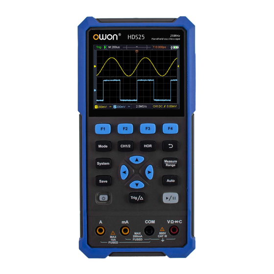
3. How to Use the Oscilloscope The Structure of the Oscilloscope Front Panel and Keys The front panel and keys of the oscilloscope are shown in Figure 3- 1: Figure 3- 1:Front Panel of the Oscilloscope... - Page 12 Description: 1. CH1 and CH2 input connectors. 2. Waveform generator output connector (optional). 3. Display area. 4. The F1 - F4 keys are multi-function keys. In each menu mode, press the corresponding key to select the corresponding menu item. 5. After pressing the HOR key, through the key , you can change the horizontal time base setting, and observe the change of the state information caused by it;...
-
Page 13: Side Panel
15. Enter the system settings key. 16. Switch key for working state of oscilloscope and multimeter. 17. CH1 / CH2 - channel switch key. Side Panel Figure 3- 2: Side Panel of the Oscilloscope Description: 1. Probe compensation: 3.3V/1kHz square wave signal output. 2. -
Page 14: Introduction To The User Interface Of The Oscilloscope
Introduction to the User Interface of the Oscilloscope Figure 3- 3:Oscilloscope Interface Description: 1. The trigger status indicates the following information: Auto: Automatic mode. The waveform is being collected without triggering. Trig: A trigger has been detected and post trigger information is being collected. -
Page 15: Functional Check
7. It indicates that there is a USB disk connecting. 8. Battery power and external power supply indication. 9. Channel 1 waveform. 10. The pointer indicates the trigger electrical level position of the channel. 11. Channel 2 waveform. 12. The icon indicates trigger-related information, including trigger channel, coupling mode, trigger type and trigger electrical level. -
Page 16: Probe Compensation
System, the default probe menu attenuation coefficient setting value is 10X. 2. The switch on the oscilloscope probe is set to 10X and connected with the CH1 channel. Align the slot on the probe with the plug on the bayonet nut connector (BNC) of the CH1 connector and insert it, then turn the probe to the right and tighten it. -
Page 17: Probe Attenuation Coefficient Setting
probe to 10X (see "Probe Attenuation Coefficient Setting" in P9), and connect with CH1. If a hook probe is used, make sure it is in close contact with the probe. Connect the probe tip to the signal output connector of the probe compensator, and connect the reference wire clamp to the ground wire connector of the probe compensator, and then press the Auto key on the front panel. -
Page 18: Safe Use Of Probe
valid until it is changed again. Note: The preset setting of the probe attenuation coefficient in the menu when the oscilloscope is delivered is 10X. Make sure that the attenuation switch setting value on the probe is the same as the probe attenuation coefficient option in the oscilloscope menu. -
Page 19: Vertical System
Before making any measurements, connect the probe to the instrument and connect the ground terminal to the ground. Vertical System The vertical system can be used to adjust the vertical scale, the position and other settings of the channel. Each channel has a separate vertical menu, which can be set individually for each channel. -
Page 20: Horizontal System
The bandwidth of the oscilloscope. Horizontal System Press the HOR key to enter the horizontal system setting menu. Use the direction keys to change the horizontal scale (time base) and horizontal trigger position. When changing the horizontal scale, the waveform is enlarged or reduced relative to the center of the screen. -
Page 21: The Automatic Measurement Of Voltage Parameters
9 types of measurement can be displayed at the bottom left of the screen. For bandwidth ≤100MHz models, automatic range types include Frequency, Period, Amplitude, Maximum, Minimum, Peak-to-Peak value, Mean, and RMS. For bandwidth 200MHz models, automatic range types include Frequency, Period, Amplitude, Maximum, Minimum, Peak-to-Peak value, Mean, RMS, Rise Time, Fall Time, +PulseWidth, -PulseWidth. -
Page 22: The Automatic Measurement Of Time Parameters
Figure 3- 9 Mean: The arithmetic mean over the entire waveform. PK-PK: Peak-to-Peak Voltage. RMS: The true Root Mean Square voltage over the entire waveform. Max: The maximum amplitude. The most positive peak voltage measured over the entire waveform. Min: The minimum amplitude. The most negative peak voltage measured over the entire waveform. -
Page 23: Cursor Measurement
+D width: The width of the first positive pulse in 50% amplitude points. -D width: The width of the first negative pulse in the 50% amplitude points. Cursor Measurement Press and F2 key to realize cursor measurement. The description of Cursor Measurement Menu is as follows: Function Description Setting... -
Page 24: Display Unknown Signals Using Automatic Settings
Display unknown signals using automatic Settings The automatic setting function enables the oscilloscope to automatically display and measure unknown signals. This function optimizes position, range, timebase, and trigger and ensures a stable display of any waveform. This feature is particularly useful for quickly checking several signals. To enable auto-setup, perform the following steps: 1. -
Page 25: Save Settings
Function Description Setting Menu Set Channel 1 as the source trigger signal. Source Set Channel 2 as the source trigger signal. Set to prevent DC component from passing Coupling through. Set to allow all components to pass through. Auto Waveforms can be acquired without detecting trigger conditions. - Page 26 Function Description Setting Menu Object Set waveform name. Save the current parameter settings of the Save oscilloscope to the internal memory. Call the settings saved in the current storage Recall location. Reference Waveform The actual waveform can be compared with the reference waveform to find out the difference.
-
Page 27: System Settings
The description of File menu is as follows: Function Description Setting Menu wave1 File wave2 Select the file name of the stored name wave3 waveform. wave4 Wave Select the waveform channel to be Source saved. Store the waveform of the source in Save a csv file named by the specified file File... -
Page 28: Default Setting
The description of the menu is as follows: Function Description Setting Menu Language Set the menu language. 10 min Set the automatic shutdown time. Unlimited Shutdown 30 min means no shutdown. Please pay attention to this Time 60 min setting if you use the battery only. Unlimited Enter the next menu After pressing this key, the instrument model,... -
Page 29: Automatic Calibration
Automatic Calibration The automatic correction program can quickly make the oscilloscope reach the best condition to obtain the most accurate measurement value. You can execute this program at any time, but if the ambient temperature variation range reaches or exceeds 5℃, you must execute this program. To perform automatic correction, disconnect all probes or wires from the input connector. -
Page 30: How To Use The Multimeter
4. How to Use the Multimeter About This Chapter This chapter introduces the multimeter function of the oscilloscope step by step, and provides some basic examples of basic operations and how to use the menu. Instrument Interface The multimeter uses four 4-mm safety banana plug input ends: A, mA, COM, Multimeter interface: Multimeter Interface Description:... - Page 31 Resist ------ Resistance measurement Diode ------ Diode measurement Cont ------ On/Off measurement ------ Capacitance measurement 2.Range indication: Manual means manual range; Auto means automatic range. 3. Current measurement range. 4. Indicating that there is a USB cable inserted. 5. Battery power indication. 6.
-
Page 32: How To Use The Waveform Generator(Optional)
5. How to Use the Waveform Generator(optional) The instrument can provide 4 basic waveforms, sine wave, square wave, ramp wave, pulse wave, and 8 arbitrary waveforms. Connect the output Press the Mode button to switch the instrument interface to the waveform generator function interface. -
Page 33: Set The Load
Set the load 1. Press the System key to enter the system function menu. 2. Press the F4 key to enter the next page of menu. key to switch High Z / *Ω ("*" represents a value, the 3. Press the default is 50Ω). -
Page 34: Output The Square Waveform
Set the Offset / Low level Press the key to switch to the Offset/Low level parameter, and then use the direction keys to set the desired value in the parameter column. Press F2 to switch between Offset / Low level. Output the square waveform Press the F1 key to enter the square waveform setting interface. -
Page 35: Output The Arbitrary Waveform
Set the Pulse Width / Duty Cycle of the pulse waveform Press the key to switch to the Pulse width/Duty parameter, use the direction keys to set the desired value in the parameter column. Press F2 to switch between Pulse width / Duty. Set the Rise Time/Fall Time Press the F3 or F4 key to switch to the Rise Time/Fall Time parameter, use the... -
Page 36: Communication With Pc
6. Communication with PC The oscilloscope supports communications with a PC through USB. You can use the Oscilloscope communication software to store, analyze, display the data and remote control. To learn about how to operate the software. Please download the oscilloscope communication software on our official download website and view it. -
Page 37: Troubleshooting
7. Troubleshooting 1. The oscilloscope cannot be turned on. It may be that the battery is completely exhausted. At this time, even if the oscilloscope is powered by the power adapter, the oscilloscope cannot be turned on. You need to charge the battery first, and do not turn on the oscilloscope. - Page 38 RUN/STOP. Check whether the trigger mode of the trigger mode menu is normal or single, and the trigger electrical level is out of the waveform range. If so, center the trigger electrical level or set the trigger mode to automatic. In addition, you can press Auto to automatically complete the above settings.
-
Page 39: Technical Specifications
5 ℃ , the system function menu must be opened to execute the "automatic correction" program (see automatic correction in "System Settings" on P18). All specifications are guaranteed except those marked "typical". Oscilloscope Characteristics Description HDS25(S) 25 MHz HDS242(S) 40 MHz Bandwidth HDS272(S) 70 MHz... - Page 40 Characteristics Description Probe attenuation 1X 、10X、100X、1000X 、10000X Maximum input 400 V (DC + AC ,PK - PK) voltage Bandwidth limit 20 MH(except HDS25(S)) ,Full bandwidth Sampling rate range 0.25 Sa/s~250 MSa/s Waveform (Sinx)/x interpolation HDS25(S) 5ns/div - 1000s/div,Stepping in HDS242(S)
-
Page 41: Multimeter
Characteristics Description DC gain accuracy Cursor ΔV, ΔT HDS25(S) HDS242(S) Period, Frequency, Mean, HDS272(S) PK-PK, Max, Min, Amplitude Measurement HDS2102(S) Automatic Period, Frequency, Mean, PK-PK, Max, Min, Amplitude, HDS2202(S) RMS,Rise Time,Fall Time, +PulseWidth, -PulseWidth Source CH1, CH2 Type Edge Coupling... - Page 42 Minimum Basic function Range Accuracy resolution 2.0000V 0.1mV 20.000V ±(0.3%+5dig) 200.00V 0.01V 1000.0V 0.1V 200.00mV 0.01mV 2.0000V 0.1mV ±(0.8%+10dig) 20.000V AC voltage 200.00V 0.01V 750.0V 0.1V ±(1%+10dig) Frequency range:40Hz-1000Hz 200.00mA 0.01mA ±(0.8%+10dig) 10.000A ±(2.5%+10dig) DC current Overload protection: mA function: self-healing fuse 400 mA/250 V; Ampere function: 10 A/600 V, D5.2*20, fast-acting fuse 200.00mA 0.01mA...
-
Page 43: Arbitrary Waveform Generator (Optional)
[1] : When measuring AC voltage/current or capacitance, accuracy guarantee range is 5% to 100% of the range. Arbitrary Waveform Generator (Optional) Characteristics Description HDS242(S) 0.1Hz~25MHz HDS272(S) HDS2102(S) Sine HDS2202(S) HDS25(S) 0.1Hz~10MHz Waveform Frequency Square 0.1Hz~5MHz Ramp 0.1Hz~1MHz Pulse 0.1Hz~5MHz 0.1Hz~5MHz Sampling 125MSa/s Amplitude(50Ω... -
Page 44: General Technical Specifications
Display color 65536 colors Display Contrast Adjustable Power supply: Characteristics Description 100 - 240 VACRMS, 50/60 Hz, CAT Ⅱ Power supply DC INPUT: 5VDC, 2A Power HDS25(S) consumption HDS242(S) <5 W HDS272(S) HDS2102(S) HDS2202(S) ≤6 W Battery HDS25(S) HDS242(S) 2200mAh*2(3.7V,18650)... -
Page 45: Appendix
9. Appendix Appendix A: List of Accessories 1 power adapter (HDS242(S)/HDS272(S)/HDS2102(S)/HDS2202(S)) 1 USB cable 1 passive probes 1 crocodile clip cable (HDS242/HDS272/HDS2102/HDS2202) 2 crocodile clip cable (HDS242S/HDS272S/HDS2102S/ HDS2202S) 1 set of multimeter probes (one red and one black) ... -
Page 46: Charging And Replacement Of Battery
instrument or probe. Warning: Please make sure the instrument is dry before re-energizing to avoid electrical short circuit or personal injury caused by moisture. Charging and Replacement of Battery During the long-term storage of the device, the battery may be too low due to the self-discharge of the lithium battery and the device cannot be turned on. -
Page 47: Replacement Of Lithium Battery
Charge the oscilloscope through the USB interface: Connect the oscilloscope to a computer or other equipment through a USB data cable for charging (pay attention to the load capacity of the power supply equipment to avoid abnormal operation of the equipment). Note To avoid overheating of the battery during charging, the ambient temperature must not exceed the allowable value given in the technical specifications.
Need help?
Do you have a question about the HDS25 and is the answer not in the manual?
Questions and answers