Sign In
Upload
Download
Table of Contents
Contents
Add to my manuals
Delete from my manuals
Share
URL of this page:
HTML Link:
Bookmark this page
Add
Manual will be automatically added to "My Manuals"
Print this page
×
Bookmark added
×
Added to my manuals
Manuals
Brands
Owon Manuals
Test Equipment
HDS300 Series
Quick manual
Owon HDS300 Series Quick Manual
Dual channel handheld oscilloscope
Hide thumbs
1
2
3
Table Of Contents
4
5
6
7
8
9
10
11
12
13
14
15
16
17
18
19
20
21
22
23
24
page
of
24
Go
/
24
Contents
Table of Contents
Troubleshooting
Bookmarks
Table of Contents
Table of Contents
Safety Information
How to Implement the General Inspection
How to Use the Oscilloscope
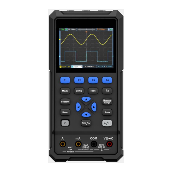
The Structure of the Oscilloscope
Front Panel and Keys
Side Panel
Introduction to the User Interface of the Oscilloscope
Functional Check
Probe Compensation
Probe Attenuation Coefficient Setting
Safe Use of Probe
How to Use the Multimeter
About this Chapter
Instrument Interface
How to Use the Waveform Generator(Optional
Connect the Output
Set the Waveform
Troubleshooting
Appendix
Appendix A: List of Accessories
Appendix B: Maintenance and Cleaning
Advertisement
Quick Links
1
How to Use the Multimeter
Download this manual
HDS300 Dual Channel Series
Handheld Oscilloscope Quick Guide
◼ HDS307S
◼ HDS310S
◼ HDS320S
For product support, visit:
www.owon.com.hk/download
Table of
Contents
Previous
Page
Next
Page
1
2
3
4
5
Advertisement
Table of Contents
Need help?
Do you have a question about the HDS300 Series and is the answer not in the manual?
Ask a question
Questions and answers
Related Manuals for Owon HDS300 Series
Test Equipment Owon HDS200 Series User Manual
Single channel handle oscilloscope (44 pages)
Test Equipment Owon HDS200 Series Quick Manual
Dual channel handheld oscilloscope (25 pages)
Test Equipment Owon HDS272S User Manual
Handheld oscilloscope (44 pages)
Test Equipment Owon HDS2202 Quick Manual
Handheld oscilloscope (24 pages)
Test Equipment Owon HDS241 Quick Manual
Single channel handheld oscilloscope (28 pages)
Test Equipment Owon HDS25 User Manual
Handheld oscilloscope (47 pages)
Test Equipment Owon HDS307S Quick Manual
Dual channel handheld oscilloscope (24 pages)
Test Equipment Owon HDS310S Quick Manual
Dual channel handheld oscilloscope (24 pages)
Test Equipment Owon HDS320S Quick Manual
Dual channel handheld oscilloscope (24 pages)
Test Equipment Owon HDS271 Quick Manual
Single channel handheld oscilloscope (28 pages)
Test Equipment Owon HDS20 Series Quick Manual
Handheld oscilloscope (26 pages)
Test Equipment Owon HDS25 (S) User Manual
Handheld oscilloscope (45 pages)
Test Equipment Owon PDS series User Manual
Pds series portable lcd digital storage oscilloscope (70 pages)
Test Equipment Owon MSO series User Manual
Portable mixed signal digital storage oscilloscope (108 pages)
Test Equipment Owon SDS5032E(V User Manual
Smart digital storage oscilloscopes (90 pages)
Test Equipment Owon tds series User Manual
Touchscreen digital storage oscilloscopes (82 pages)
This manual is also suitable for:
Hds307s
Hds310s
Hds320s
Table of Contents
Print
Rename the bookmark
Delete bookmark?
Delete from my manuals?
Login
Sign In
OR
Sign in with Facebook
Sign in with Google
Upload manual
Upload from disk
Upload from URL


Need help?
Do you have a question about the HDS300 Series and is the answer not in the manual?
Questions and answers