Table of Contents
Advertisement
Quick Links
Advertisement
Table of Contents

Related Manuals for Shop fox SHOP FOX W1813


Summary of Contents for Shop fox SHOP FOX W1813
-
Page 3: Table Of Contents
Woodstock Technical Support ....2 Sander Accessories ......26 Machine Overview ........ 2 General .......... 27 Standard Machinery Safety ..... 7 Cleaning ......... 27 Lubrication ........27 Additional Safety for Wide Belt Sanders ..9 Air Regulator/Filter ......28 220V Operation ......... 10 Extension Cords ........ - Page 4 Woodstock International, Inc. is committed to customer satisfaction. Our intent with this manual is to include the basic information for safety, setup, operation, maintenance, and service of this product.
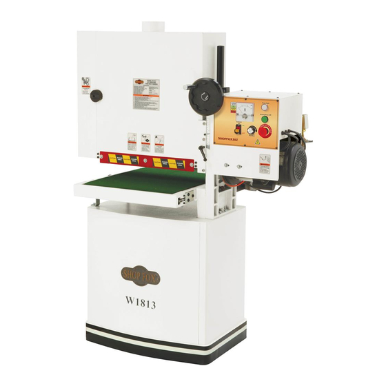
- Page 5 Model W1813 features. Sanding Cabinet Motor 3 HP Dust Port 4" Elevation Lock Lever Elevation Handwheel Cabinet Stand Control Panel (refer to Conveyor for details) & Electrical Box Depth of Cut Safety Bar Air Regulator & Safety Switch Sanding Belt Access Door...
- Page 6 Sanding cabinet controls. Control panel identification. Upper Roller Amperage Load Chart Left Oscillation Disc Amperage Load Meter Oscillation Control Valve Power Light Sanding Belt Tension Lock Lever Sanding Motor ON Button Sanding Belt Tension Lever Emergency Stop Button Sanding Drum Conveyor Feed Rate Dial Sanding Belt 19"...
- Page 7 Phone #: (360) 734-3482 • Online Tech Support: tech-support@shopfox.biz • Web: www.shopfox.biz Weight ........................475 lbs. Length/Width/Height .................. 42 ⁄ " x 24" x 62 ⁄ " Foot Print (Length/Width) ..................25" x 17 ⁄ " Type ..................Wood Pallet + Cardboard Content ......................
- Page 8 Type ..................Direct Current Variable Speed Horsepower ......................⁄ Voltage ......................220VDC Phase ........................ Single Amps ........................1A Number of Speeds ....................Variable Speed ......................10–34 RPM Cycle ......................... 60 Hz Power Transfer ....................Gearbox Bearings ..................Sealed and Lubricated Number of Sanding Drums ..................... 1 Maximum Board Width ....................
- Page 11 Kickback is typically defined as the high-speed expulsion of stock from the machine, which can cause serious personal injury to the operator or bystanders. Forcing or jamming the workpiece into the sander or against the sanding belt can cause it to kickback into the operator. Always use the correct depth of cut, then firmly hold the workpiece and ease it into the sander at the same feed rate as the conveyor.
-
Page 12: Extension Cords
The Model W1813 is wired for 220V single-phase opera- NEMA 6-20 plug and receptacle. tion. We recommend connecting this machine to a dedi- cated circuit with a verified ground, using the circuit size given below. Never replace a circuit breaker with one of higher amperage without consulting a qualified electri- cian to ensure compliance with wiring codes. -
Page 13: Inventory
This machine has been carefully packaged for safe trans- portation. If you notice the machine has been damaged during shipping, please contact your authorized Shop Fox dealer immediately. The following is a description of the main components shipped with the Model W1813. Lay the components out to inventory them. - Page 14 The table and other unpainted parts of your This machine distributes a wide belt sander are coated with a waxy grease heavy load in a small footprint. Some resi- that protects them from corrosion during ship- dential floors may require additional brac- ing to support both machine and operator.
- Page 15 Wrench ⁄ " ............1 Wrench ⁄ " ............1 Precision Level ..........1 With assistance, turn the cabinet stand upside down on a protective piece of cardboard. Place ⁄ " flat washers on the mounting feet, then insert them through the machine mounting holes of the base (see Reach into the cabinet and secure the feet with the ⁄...
- Page 16 Lift and move the sander assembly into position over the cabinet stand so that the mounting holes line up (see Secure the sander assembly to the cabinet stand with the four M8-1.25 x 25 hex bolts and 8mm flat washers. Open the sanding belt access door on the left side of the machine, and remove the red shipping brace securing the sanding drum to the conveyor assembly...
-
Page 17: Compressed Air
A steady supply of clean, dry air of 57–60 PSI (not to exceed 120 PSI) is required for the operation of the sanding belt oscillation system and pneumatic motor To avoid possible personal injury from brake. Without the correct supply of compressed air, the exploding compressed air components machine will not start. -
Page 18: Test Run
Once the assembly is complete, test run your machine to make sure it runs properly and is ready for regular opera- tion. The test run consists of verifying the following: 1) The motors power up and run correctly, 2) the emergency stop button safety feature works correctly, 3) the conveyor ON/ OFF switch disabling key works correctly, and 4) the air pressure safety switch operates properly. - Page 19 Reset the emergency stop button, then turn the sanding motor Turn the conveyor and verify that it operates correctly—it should move from front-to-back. Use the conveyor feed rate dial to vary the speed. Turn the conveyor , then remove the switch dis- abling key, as shown in Try to turn the conveyor Removing the switch disabling...
- Page 20 This machine will perform many types of operations that are beyond the scope of this manual. Many of these operations can be dangerous or deadly if performed incor- rectly. The instructions in this section are written with the understanding that the operator has the necessary knowl- edge and skills to operate this machine.
- Page 21 Refer to and the following descriptions to become familiar with the basic controls of your sander. Basic controls. Displays the amper- Controls the age range for safe operation of the sanding feed rate of the conveyor between 5 and motor. NEVER operate the sander above the 17 feet per minute (FPM).
-
Page 22: General
Sanding Belt Dimensions ......19"W x 48"L There are many types of sanding belts to choose from. We recommend aluminum oxide for general workshop envi- ronments. The grit you choose will depend on the type of operation, the species of wood, and the stage of finishing. As a gen- eral guideline, refer to the chart below to help you select the right grit for your operation. -
Page 23: Conveyor Feed Rate
To release the tension on the sanding belt, move the tension lever up and to the right out of the top Catch catch, then use moderate force to push it down and under the bottom catch, as shown in Bottom Pull the sanding belt off the upper roller and the Catch sanding drum. -
Page 24: Amperage Load Meter
Maximum Depth of Cut ....Approx. 0.016" ( ⁄ ") Elevation Handwheel The optimum depth of cut will vary based on the type of wood, conveyor feed rate, and sandpaper grit. Attempting to remove too much material can cause jamming, wood Safety Bar burning, rapid sanding belt wear or tearing, poor finish, or belt slippage. - Page 25 To prevent sanding "streaks" in the workpiece and ensure NOTICE an even finish, the sanding belt oscillates from side-to- side on the sanding drum during operation. This action is caused by the twisting motion of the upper sanding roller that causes the sanding belt to shift along the roller until it hits the oscillation disc at the end, which then causes the sanding belt to reverse direction to the other end.
-
Page 26: Sanding Operation
Follow these instructions to ensure safe sanding operation and quality results: Starting the sanding motor with a • Replace the sandpaper with a higher grit to achieve workpiece in contact with the sand- a finer finish (refer to ing belt could cause the workpiece to kickback into the operator resulting in serious personal injury. - Page 27 DO NOT sand more than one board at Read and follow the safety instructions at the begin- a time side-by-side. Minor variations ning of the manual, and make sure the machine is in workpiece thickness can cause one set up properly before starting the sander. board to be propelled into the operator at a high rate of speed by the sanding Connect the source of compressed air to the sander...
-
Page 28: Sander Accessories
Dealer. If you do not have a dealer in your area, these products are also available through online deal- ers. Please call or e-mail Woodstock International Inc. Customer Service to get a current listing of deal- ers at: 1-800-840-8420 or at sales@woodstockint.com. -
Page 29: Lubrication
Regular periodic maintenance on your machine will ensure its optimum performance. Make a habit of inspecting your machine each time you use it. Loose mounting bolts. Worn switch. Worn or damaged cords and plugs. Damaged or worn sanding belt. • Damaged, loose, or worn conveyor belt. - Page 30 Clean away any debris and built-up grime from the surfaces of the ways, then apply a thin coat of ISO 68 lubricant or an equivalent. Move the sanding cabinet through its entire elevation range of motion to evenly distribute the oil. Hex Wrench 4mm ..........1 DISCONNECT THE SANDER FROM POWER! Loosen the set screw in the elevation handwheel...
- Page 31 If you require additional machine service not included in this section, please contact Woodstock International Technical Support at (360) 734-3482 or send e-mail to: The conveyor belt may stretch with extended use, causing it to slip on the conveyor rollers.
-
Page 32: Conveyor Belt Tracking
Turn both adjustment bolts clockwise one full turn at a time until there is an approximate ⁄ " hanging gap on the underside of the conveyor belt. The conveyor roller assemblies and belt pose an entanglement hazard. Take Take another reading of the reference measurement extra care when performing the con- on both sides of the conveyor and make sure they veyor belt tensioning or tracking proce-... -
Page 33: Gib Adjustment
The gib is sandwiched between the stationary and moving surfaces of the sander assembly and the dovetail ways. The gib controls the accuracy of the sander assembly movement along these ways. A tight gib makes the move- ment more accurate but harder to move, and will lead to premature wear of the ways. - Page 34 The sanding drum and conveyor must be parallel to one another to obtain accurate sanding results. This setting is made at the factory and should not have to be made again. However, if it is necessary to adjust the sanding drum and conveyor parallel to each other, follow the pro- cedure below.
-
Page 35: Sanding Drum & Conveyor Parallelism
Hex Wrench 6mm ..........1 Hex Wrench 8mm ..........1 Loosen the four column mounting cap screws on the right side of the column base shown in Mounting Cap Screws Adjust the jack screws evenly to bring the sanding drum and conveyor parallel to each other within 0.005"... -
Page 36: Air Pressure Safety Switch
The sanding motor safety brake and the sanding oscilla- Sensitivity Adjustment Screw tion system require at 57–60 PSI of air pressure connected to the machine to operate. The air pressure safety switch (see ) measures the amount of air pressure flow- ing into the machine. -
Page 37: Depth Of Cut Safety Bar
When properly adjusted, the depth of cut safety bar prevents the operator from sanding a workpiece that is beyond a safe height and that could become a kickback hazard. The position of this safety bar (see ) was set by Hex Bolts the factory at approximately 0.047"... - Page 38 The height of the pressure rollers (see ) is set slightly below the bottom of the sanding drum to keep the workpiece firmly against the conveyor belt as it passes through the sander, preventing workpiece kickback. The pressure roller height was set by the factory at Pressure Rollers approximately 0.063"...
- Page 39 If the conveyor belt becomes damaged or too worn to prop- Sander Assembly erly adjust the tension, you must replace it. Mounting Brackets Hex Wrench 4mm ..........1 Hex Wrench 5mm ..........1 Wrench 10mm ...........1 Wrench 12mm ...........1 Roller Guards DISCONNECT THE SANDER FROM POWER! Sander assembly mounting Remove the cap screws and flat washers securing brackets and conveyor roller guards.
- Page 40 Remove the three cap screws securing the left rear Rear Conveyor conveyor roller bracket to the conveyor support, but Roller Bracket leave the roller assembly and the bracket in place, as shown in Hex Bolt (1 of 2) NOTICE Loosen, but do not remove, the upper cap screws on Rear conveyor roller bracket the left side of the conveyor assembly that secure unattached from the conveyor support.
- Page 41 These pages are current at the time of printing. However, in the spirit of improvement, we may make changes to the electrical systems of future machines. Study this diagram carefully. If you notice differ- ences between your machine and these wiring diagrams, call Woodstock International Technical Support at (360) 734-3482.
-
Page 42: Electrical Box & Control Panel
Refer to Air Pressure Air Pressure Brake Solenoid Safety Switch (Diagram: (Diagram: Electrical Box & Control Panel (Photo: Diagram: Conveyor Motor (Diagram: Sanding Motor (Diagram: READ ELECTRICAL SAFETY -40- ON PAGE 39! - Page 43 electrical box photo Conveyor DC Motor Control Contactor & Overload Relay Electrical box wiring (Diagram: Power Lamp Amperage Load Meter Sanding Motor ON Button Conveyor Conveyor ON/ Feed Rate OFF Switch Dial Emergency Stop Button Control panel wiring (Diagram: READ ELECTRICAL SAFETY -41- ON PAGE 39!
- Page 44 electrical box diagram To Conveyor Motor To Air Pressure Safety Switch DC Motor Control 13NO (Conveyor Motor) To Air Pressure NHD C-09D Brake Solenoid 220V 14NO To Sanding Motor NHD NTH-17 Ground Power Light Ground Sanding Motor ON Button Amp Load Meter Emergency Stop Coveyor...
-
Page 45: Electrical Components
electrical components Sanding Motor Sanding motor wiring. Sanding motor wiring diagram. Conveyor Motor Conveyor motor wiring. Conveyor motor wiring diagram. Air Pressure Air Pressure Safety Switch Safety Switch Electrical Box Air Pressure Brake Electrical Box Air Pressure Solenoid Brake Solenoid Air pressure safety switch and brake Air pressure safety switch and brake solenoid. - Page 46 pneumatic system Air Pressure Safety Switch Oscillation Cylinder Air Regulator 4-Way Valve Oscillation Valve Air Pressure Brake Solenoid Sanding Motor Brake Unit Shop Air Compressor Refer to -44-...
- Page 47 This section covers the most common problems and corrections with this type of machine. Machine does not start 1. Switch disabling key removed. 1. Install switch disabling key. or a breaker trips. 2. Emergency stop push-button engaged/ 2. Rotate button to reset/replace it. faulty.
- Page 48 1. Store sanding belts away from extremely dry/ Grit rubs off sanding 1. Sanding belt has been stored in an incor- belt easily. rect environment. moist environment or hot temperatures. 2. Sanding belt has been folded or 2. Store sanding belt flat, not folded or bent. smashed.
- Page 49 parts -47-...
- Page 50 PART # DESCRIPTION PART # DESCRIPTION X1813101 CONVEYOR TABLE XPW04M FLAT WASHER 10MM X1813102 CONVEYOR ROLLER BRACKET LR XPLW06M LOCK WASHER 10MM XPS16M PHLP HD SCR M8-1.25 X 16 XPLN05M LOCK NUT M10-1.5 X1813104 BALL BEARING 6003ZZNR XPSB11 CAP SCREW 5/16-18 X 1-1/4 X1813105 CONVEYOR ROLLER REAR X1813154...
- Page 51 PART # DESCRIPTION PART # DESCRIPTION X1813194 CONNECTING TUBE X1813228 SPECIAL SCREW X1813195 4-WAY VALVE X1813229 SPACER X1813196 AIR INLET 1/4 NPT XP608 BALL BEARING 608ZZ X1813197 CONNECTOR XPW01M FLAT WASHER 8MM X1813198 AIR PRESSURE SAFETY SWITCH X1813232 BRACKET X1813199 AIR PRESSURE BRAKE SOLENOID XPS06M PHLP HD SCR M5-.8 X 20...
- Page 52 Back of Machine PART # DESCRIPTION PART # DESCRIPTION X1813301 MACHINE ID LABEL XPLABEL-55 ENTANGLEMENT HAZARD LABEL X1813302 MODEL NUMBER LABEL XPLABEL-37 EYE/LUNG HAZARD LABEL VERT X1813303 ELEVATION HANDWHEEL LABEL XPLABEL-12A READ MANUAL LABEL VERT X1813304 CONTROL PANEL LABEL X1813312 HAND INJURY LABEL VERT XPLABEL-63 DISCONNECT WARNING LABEL XPPAINT-7...
- Page 53 Name ___________________________________________________________________________________ Street __________________________________________________________________________________ City _________________________ State ___________________________Zip ________________________ Phone # ______________________ Email___________________________Invoice # ___________________ Model #_________Serial #______________Dealer Name__________________Purchase Date___________ How did you learn about us? _____ Advertisement _____ Friend ____ Local Store _____ Mail Order Catalog _____ Website ____ Other: How long have you been a woodworker/metalworker? _____ 0-2 Years _____ 2-8 Years...
- Page 54 FOLD ALONG DOTTED LINE Place Stamp Here FOLD ALONG DOTTED LINE TAPE ALONG EDGES--PLEASE DO NOT STAPLE...
Need help?
Do you have a question about the SHOP FOX W1813 and is the answer not in the manual?
Questions and answers