
Related Manuals for Moxa Technologies EDS-2005-ELP Series


Summary of Contents for Moxa Technologies EDS-2005-ELP Series
- Page 1 EDS-2005-EL/ELP Series Quick Installation Guide Moxa EtherDevice Switch Version 1.1, January 2021 Technical Support Contact Information www.moxa.com/support 2021 Moxa Inc. All rights reserved. P/N: 1802020003021 *1802020003021*...
-
Page 2: Package Checklist
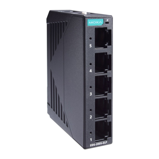
Overview The EDS-2005-EL/ELP Series has a 5-port combination to simplify network expansion. There are two housing types available for the user to select depending on the requirements of their application. The ELP has a plastic housing and the EL has a metal housing. The compact switches provide a cost-effective solution for your industrial Ethernet connection requirements. - Page 3 Features High Performance Network Switching Technology • 10/100BaseT(X) auto-negotiation speed, full/half duplex mode, auto MDI/MDI-X connection. • IEEE 802.3 for 10BaseT, IEEE 802.3u for 100BaseT(X). • IEEE 802.1p for Quality of Service (QoS) traffic prioritized function. • Store-and-forward switching process type. Industrial-grade Reliability •...
- Page 4 Panel Layout of EDS-2005-EL/EDS-2005-ELP 1. Chassis ground screw 2. Terminal block for power input 3. DIP switch 4. Power LED 5. 10/100 BaseT(X) Port 6. 10/100 BaseT(X) Port LED 7. Port number 8. Model name - 4 -...
-
Page 5: Mounting Dimensions
Mounting Dimensions EDS-2005-EL Series EDS-2005-ELP Series - 5 -... -
Page 6: Din Rail Mounting
DIN-rail Mounting When shipped, the DIN-rail mounting kit is fixed to the back panel of the EDS. Mount the EDS on the corrosion-free mounting rail that adheres to the EN 60715 standard. Suggested Installation Method STEP 1: Insert the upper lip of the DIN-rail kit into the mounting rail. -
Page 7: Wall Mounting (Optional)
Wall Mounting (optional) For some applications, you will find it convenient to mount EDS on the wall, as illustrated below. There are two options for installation: The first option is to hook the EDS DIN-rail latch on the opening of the wall mount kit (see picture above) and then mount the wall-mount kit on the wall with screws. -
Page 8: Wiring Requirements
Wiring Requirements WARNING Do not disconnect modules or wires unless the power supply has been switched off or the area is known to be non-hazardous. The devices may only be connected to the supply voltage shown on the type plate. The devices are designed for operation with a Safety Extra-Low Voltage. -
Page 9: Wiring The Power Input
Grounding Moxa EtherDevice Switch Grounding and wire routing help limit the effects of noise due to electromagnetic interference (EMI). Run the ground connection from the ground screw to the grounding surface prior to connecting devices. A 4 mm conductor must be used when a connection to the external grounding screw is utilized. -
Page 10: Communication Connections
ATTENTION One individual conductor in a clamping point with 28-14 AWG wire size, and a torque value of 1.7 lb-in should be used. ATTENTION The cable that is connected to the field wiring terminals must be capable of withstanding at least 105°C. Communication Connections The EDS-2005-EL/ELP models have 10/100BaseT(X) Ethernet ports. -
Page 11: Dip Switch Settings
DIP Switch Settings DIP Switch Setting Description Quality of Enable the Quality of Service to handle packet Service (QoS) priorities in four WRR queues. QoS priority mapping matrix in each queue QoS 3bit priority 7, 6 5, 4 3, 2 1, 0 Queues Disable the Quality of Service. -
Page 12: Dual Speed Functionality And Switching
Dual Speed Functionality and Switching The EDS’s 10/100 Mbps RJ45 switch port auto negotiates with the connected device for the fastest data transmission rate supported by both devices. The EDS is a plug-and-play device, so software configuration is not required at installation or during maintenance. The half/full duplex mode for the RJ45 switched ports is user dependent and changes (by auto-negotiation) to full or half duplex, depending on which transmission speed is supported by the attached device. -
Page 13: Specifications
Specifications Technology Standards IEEE 802.3 for 10BaseT, IEEE 802.3u for 100BaseT(X) and 100Base FX, IEEE 802.1p for Class of Service Flow Control IEEE 802.3x flow control, back pressure flow control Interface RJ45 Ports 10/100BaseT(X) auto negotiation speed LED Indicators PWR, 10M/100M DIP Switch QoS, Broadcast Storm Protection (BSP) Switch Properties... - Page 14 Free Fall IEC60068-2-32 Vibration IEC60068-2-6 Warranty 5 years - 14 -...
Need help?
Do you have a question about the EDS-2005-ELP Series and is the answer not in the manual?
Questions and answers