
Related Manuals for Emerson I/O MODULE IPMC7126E


Summary of Contents for Emerson I/O MODULE IPMC7126E
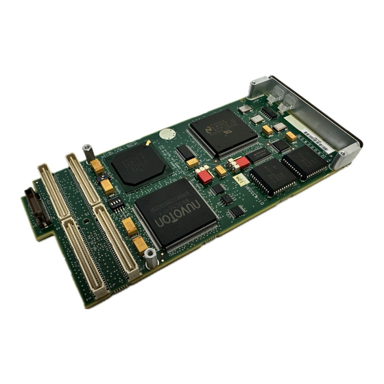
- Page 1 IPMC7126E/7616E I/O Module Installation and Use 6806800A45B September 2008 Edition...
- Page 2 While reasonable efforts have been made to assure the accuracy of this document, Emerson assumes no liability resulting from any omissions in this document, or from the use of the information obtained therein. Emerson reserves the right to revise this document and to make changes from time to time in the content hereof without obligation of Emerson to notify any person of such revision or changes.
- Page 3 The safety precautions listed below represent warnings of certain dangers of which Emerson is aware. You, as the user of the product, should follow these warnings and all other safety precautions necessary for the safe operation of the equipment in your operating environment.
- Page 4 All Emerson PWBs (printed wiring boards) are manufactured with a flammability rating of 94V-0 by UL-recognized manufacturers. This equipment generates, uses and can radiate electromagnetic energy. It may cause or be Caution susceptible to electromagnetic interference (EMI) if not installed and used with adequate EMI protection.
-
Page 5: Table Of Contents
About This Manual ..............xi Summary of Changes . - Page 6 Related Documentation ............35 Emerson Network Power - Embedded Computing Documents ......35 Manufacturers’...
- Page 7 List of Figures Figure 1-1. IPMC761 with Default Switch Setting ........4 Figure 1-2.
- Page 8 List of Figures viii IPMC7126E/7616E I/O Module Installation and Use (6806800A45B)
- Page 9 Table A-2. Power Consumption ........... . . 34 Table B-1. Emerson Network Power - Embedded Computing Publications ....35 Table B-2.
- Page 10 List of Tables IPMC7126E/7616E I/O Module Installation and Use (6806800A45B)
-
Page 11: About This Manual
Multifunction rear I/O PMC module; Ultra-Wide SCSI, one parallel port, two asynchronous and two synchronous/asynchronous serial ports Description Update document to Emerson style (logo, copyright, trademarks, etc.) IPMC7126E/7616E I/O Module Installation and Use (6806800A45B) About This Manual... -
Page 12: Comments And Suggestions
About This Manual Comments and Suggestions We welcome and appreciate your comments on our documentation. We want to know what you think about our manuals and how we can make them better. Mail comments to us by filling out the following online form: http://www.emersonnetworkpowerembeddedcomputing.com/ In “Area of Interest”... - Page 13 courier is used for system output (for example, screen displays, reports), examples, and system prompts. <Enter>, <Return> or <CR> represents the carriage return or Enter key. Ctrl represents the Control key. Execute control characters by pressing the Ctrl key and the letter simultaneously, for example, Ctrl-d.
- Page 14 About This Manual IPMC7126E/7616E I/O Module Installation and Use (6806800A45B)
-
Page 15: Product Features
Product Features The IPMC712 and IPMC761 are optional modules that provide backward compatibility with earlier Emerson products using the MVME761 or MVME712M rear transition modules. General Functionality Both models are designed around a PMC form factor and both modules incorporate a PCI-to- ISA bridge, Ultra-wide SCSI adapter, and Super I/O functionality. -
Page 16: Configurable Switches
Chapter 1 Product Features Signals routed to P14 include: narrow SCSI, parallel port, COM1 and COM2 synchronous serial ports, COM3 and COM4 synchronous serial ports, power, and P2 mux signals. The remaining SCSI data lines are routed to P15. The on-board PCI devices on each module are as follows: ■... -
Page 17: Figure 1-1. Ipmc761 With Default Switch Setting
Note SCSI signals leading to connector P15 go through zero ohm resistors (R92-R100) before terminating at P15. When the host board’s PMC slot 2 is populated, and there is an IPMC module in slot 1, there exists a possibility for contention on these signals. Figure 1-1. -
Page 18: Figure 1-2. Ipmc761 Functional Block Diagram
Chapter 1 Product Features Figure 1-2. IPMC761 Functional Block Diagram WINBOND W83C554F_(H) ISA bus Super I/O NATIONAL PC97307 IPMC7126E/7616E I/O Module Installation and Use (6806800A45B) PMC PCI BUS CONNECTORS P11, P12 IPMC761 Receptacle to Base Board ESCC 85230 Z8536 SROM (VPD) P2 MUX LOGIC... -
Page 19: Figure 1-3. Ipmc712 With Default Switch Settings
Figure 1-3. IPMC712 with Default Switch Settings PIB BUSY Table 1-2. IPMC712 Jumpers Jumper Description Reserved 9PLD programming header Port 4 Receive Clock Port 4 Transmit Clock Clock Loopback IPMC7126E/7616E I/O Module Installation and Use (6806800A45B) Chapter 1 Product Features SCSI BUSY 2843 0905 Setting... -
Page 20: Figure 1-4. Ipmc712 Functional Block Layout
Chapter 1 Product Features Figure 1-4. IPMC712 Functional Block Layout SCSI IPMC7126E/7616E I/O Module Installation and Use (6806800A45B) PMC P11 & P12 PCI bus WB-554 JSA bus Super IO ESCC National 85230 8536 PMC P14 & P15... -
Page 21: Figure 1-5. Ipmc712 Serial Port 4 Clock Configuration
Figure 1-5. IPMC712 Serial Port 4 Clock Configuration Base Board + IPMC712 Z85230 TXDB RTSB# DCDB# RXDB CTSB# TRXCB RTXCB Z8536 DTR4# LLB4# RLB4# DSR4# RI4# TM4# 64-PIN MVME712M ADAPTER CABLE MODULE IPMC7126E/7616E I/O Module Installation and Use (6806800A45B) Chapter 1 Product Features TXCI RXCI TXCO... -
Page 22: Isa Local Resource Bus
Chapter 1 Product Features ISA Local Resource Bus PCI-to-ISA Bridge (PIB) The PIB (W83C554F) contains the ISA Bridge I/O Registers necessary for various functions. These registers are also accessible from the PCI bus. Super I/O The Super I/O device (PC97307) provides the following functions on the IPMC: ■... -
Page 23: Input/Output Modes
Input/Output Modes Both modules are designed to be plugged into PMC slot 1 of the base board. As stated earlier, these SBCs have two P2 I/O modes (IPMC and PMC) that are user configurable. The user should configure the baseboard for the IPMC module being used. The jumpers route the on-board Ethernet port 2 to row C of connector P2. - Page 24 Chapter 1 Product Features IPMC7126E/7616E I/O Module Installation and Use (6806800A45B)
-
Page 25: Installing The Ipmc Module
Installing the IPMC Module This chapter discusses the configuration and installation of IPMC modules on an MVME6100, MVME5500, or MVME5100 SBCs. For additional information pertaining to the MVME51005E, refer to the information contained in the MVME51005E Single Board Computer Installation and Use manual before proceeding with these instructions contained in this chapter. -
Page 26: Before You Install Or Remove A Board
Boards may be damaged if improperly installed or handled. Please read and follow the guidelines in this section to protect your equipment. Observe ESD Precautions Emerson strongly recommends that you use an antistatic wrist strap and a conductive Use ESD foam pad when installing or upgrading a system. Electronic components, such as disk drives, computer boards, and memory modules, can be extremely sensitive to electrostatic discharge (ESD). -
Page 27: Watch For Bent Pins Or Other Damage
Watch for Bent Pins or Other Damage Bent pins or loose components can cause damage to the board, the backplane, or Caution other system components. Carefully inspect your board and the backplane for both pin and component integrity before installation. Caution ECC and our suppliers take significant steps to ensure there are no bent pins on the backplane or connector damage to the boards prior to leaving our factory. -
Page 28: Recognize Different Injector/Ejector Lever Types
Chapter 2 Installing the IPMC Module Recognize Different Injector/Ejector Lever Types The modules you install may have different ejector handles and latching mechanisms. The following illustration shows the typical board ejector handles used with ECC payload cards: (A) Elma Latching, (B) Rittal Type II, (C) Rittal Type IV. All handles are compliant with the CompactPCI specification and are designed to meet the IEEE1101.10 standards. -
Page 29: Programming
Programming Programing Details The overall design of the IPMC712 and IPMC761 is based on the PowerPlus II architecture. The programming characteristics for both modules conforms to the PowerPlusII Programming Specification. Note The PowerPlus II Programming Specification covers a large variety of programming configurations, many of which are not applicable to either module. -
Page 30: Figure 3-1. Gpio Switch Settings (S1)
Chapter 3 Programming The General Purpose I/O (GPIO) pin assignments for the SCSI Controller are shown in the table below. A 1x4 switch (S1) is provided to configure GPIO pins 2 and 3. The factory default setting shall be for Ultra-Speed and Ultra-Wide SCSI. Table 3-1. -
Page 31: Idsel Address Assignments For Pci Local Bus
Figure 3-2. IDSEL Switch Settings (S2) S2-P1 = 1 S2-P2 = 0 MVME5100 and MVME5500 S2 Default Setting The settings of SW2 determine the IDSEL used by the W83C553 PCI/ISA Bridge. It is important that the settings of P1 and P2 are neither both on nor both off, otherwise the device will be enumerated twice. -
Page 32: Pci Arbitration Assignments On Host Boards
Chapter 3 Programming The IDSEL assignments for both modules are shown below: Table 3-3. IDSEL and IDSELB Mapping for PCI Devices Device Number Field 0b0_1011 0b1_0000 0b1_0001 0b1_0101 The following table shows the Vendor ID, the Device ID, and Revision ID for each of the planar PCI devices on the IPMC712 and IPMC761: Table 3-4. -
Page 33: Mvme6100
MVME6100 The MVME6100 IPMC module PCI arbitration is performed by the MV64360 ASIC. The internal PCI arbiter REQ#/GNT# signals are multiplexed on the MV64360 MPP[31:0] pins. The internal PCI arbiter is disabled by default (the MPP pins function as general purpose inputs). Software will configure the MPP pins to function as request/grant pairs for the internal PCI arbiter. -
Page 34: Mvme5500 Ipmc Module Interrupt Assignments
Chapter 3 Programming 2. MVME5100 Hawk MPIC IRQ9 interrupt sources may be one of the following: PCI-PMC1 INTA#, PMC2 INTB#, or PCIX INTA#. MVME5500 IPMC Module Interrupt Assignments Legacy Interrupt assignments were not maintained on the MVME5500 due to the vastly different host bridge device (GT-64260) used. -
Page 35: Pci-To-Isa Bridge (Pib)
PCI-to-ISA Bridge (PIB) The PIB contains ISA Bridge I/O Registers for various functions. These registers are accessible from the PCI bus. Super I/O The Super I/O device provides the following functions: ■ Two serial ports (asynchronous) ■ Parallel port interface The device’s hardware configuration is based on two strap-pins: BADDR0 and BADDR1. -
Page 36: Isa Dma Connections/Assignments
Chapter 3 Programming 2. On the IPMC712, pins PA0 through PA4, PA6, PA7, PB0 through PB4 are not used on the Z8536 CIO. Table 3-9. Z8536 CIO Port Pins Assignment Port Pin Signal Name BRDFAIL FUSE ABORT_ Reserved BASETYP0 BASETYP1 ISA DMA Connections/Assignments The following table shows the DMA connections/assignments between the PC97307 and the PIB. -
Page 37: Interrupt Routing To Pib
Interrupt Routing to PIB Module interrupts and MVME5100 Ethernet Port 2 interrupts go through the 8259 pair and into the PIB. The output of the PIB then goes to the Hawk MPIC on the MVME5100. The table below lists the ISA interrupts routed to the PIB. Table 3-11. -
Page 38: Vital Product Data (Vpd)
Chapter 3 Programming Vital Product Data (VPD) To access VPD information for each SBC, access the registers through the I follows: ■ MVME5100 - via the Hawk ASIC; IPMC761’s VPD address is $A4. ■ MVME5500 - via the Discovery1 device GT64260 ■... -
Page 39: Connector Pin Assignments
Connector Pin Assignments This chapter provides connector pin assignments for the IPMC712 and IPMC761 modules. IPMC712 Connector This connector provides the on-board interface of the IPMC712 I/O signals. The pin assignments for this connector are as follows: Table 4-1. IPMC712 Connector Signal Description I2CSCL JDB8#... -
Page 40: Ipmc761 Connector
Chapter 4 Connector Pin Assignments IPMC761 Connector connector provides the on-board interface of the IPMC761 I/O signals. The pin assignments for this connector are as follows: Table 4-2. IPMC761 Connector Signal Description I2CSCL DB8# DB10# +3.3V DB12# DB14# +3.3V DBP1# PIB_INT +3.3V PIB_PMCGNT#... -
Page 41: Pci Interface And I/O Connectors
PCI Interface and I/O Connectors There are four 64-pin connectors on the IPMC761 (P11, P12, P13, and P14) which provide 32- bit PCI interface and P2 Input/Output (I/O) for the host board. The pin assignments are as follows: Table 4-3. PCI Connector Pin Assignments (P11) Signal Description INTB# PMCPRSNT1#... -
Page 42: Table 4-4. Pci Connector Pin Assignments (P12)
Chapter 4 Connector Pin Assignments Table 4-3. PCI Connector Pin Assignments (P11) (continued) Signal Description +5V (Vio) AD02 AD00 Table 4-4. PCI Connector Pin Assignments (P12) Signal Description +12V Not Used Not Used RST# +3.3V Not Used AD30 AD24 IDSEL1 +3.3V AD18 AD16... -
Page 43: Table 4-5. Pci Connector Pin Assignments (P13)
Table 4-4. PCI Connector Pin Assignments (P12) (continued) Signal Description Not Used ACK64# Table 4-5. PCI Connector Pin Assignments (P13) Signal Description Reserved Not Used Not Used +5V (Vio) Not Used Not Used Not Used Not Used +5V (Vio) Not Used Not Used Not Used Not Used... -
Page 44: Table 4-6. Pci Connector Pin Assignments (P14)
Chapter 4 Connector Pin Assignments Table 4-5. PCI Connector Pin Assignments (P13) (continued) Signal Description +5V (Vio) Reserved Reserved Table 4-6. PCI Connector Pin Assignments (P14) Signal Description Not Used Not Used Not Used Not Used Not Used Not Used Not Used PRSTB# PRD0... -
Page 45: Table 4-7. Pci Connector Pin Assignments (P15)
Table 4-6. PCI Connector Pin Assignments (P14) (continued) Signal Description RTS2_232 CTS2_232 Table 4-7. PCI Connector Pin Assignments (P15) Signal Description I2CSCL DB8# DB10# +3.3V DB12# DB14# +3.3V DBP1# PIB_INT +3.3V PIB_PMCGNT# +5.0V +5.0V IPMC7126E/7616E I/O Module Installation and Use (6806800A45B) Chapter 4 Connector Pin Assignments Signal Description Not Used... - Page 46 Chapter 4 Connector Pin Assignments IPMC7126E/7616E I/O Module Installation and Use (6806800A45B)
-
Page 47: Specifications
Specifications General Specifications The following table provides general specifications for the IPMC712 and IPMC761 module. Table A-1. IPMC Specifications Main Characteristic Interface SCSI Bus Synchronous Serial Ports Asynchronous Serial Ports Parallel Ports Function Specification Address/Data A32/D32/D64, PMC PN1, PN2, PN3, PN4 Connectors PCI Bus Clock 33 MHz... -
Page 48: A Specifications
Appendix A Specifications Power Requirements The table below lists the typical and maximum power consumption of the IPMC712 and IPMC761 modules. Table A-2. Power Consumption Supply Voltage +5V (±5%) +12V (±10%) -12V (±10%) IPMC7126E/7616E I/O Module Installation and Use (6806800A45B) Amps (Typical) Amps (Maximum) 0.5 A... -
Page 49: Related Documentation
Documents The Emerson Network Power - Embedded Computing publications listed below are referenced in this manual. You can obtain electronic copies of Emerson Network Power - Embedded Computing publications by contacting your local Emerson sales office. For documentation of final released (GA) products, you can also visit the following website: www.emersonnetworkpower.com/embeddedcomputing... -
Page 50: B Related Documentation
Appendix B Related Documentation Manufacturers’ Documents For additional information, refer to the following table for manufacturers’ data sheets or user’s manuals. For your convenience, a source for the listed document is also provided. Note In many cases, the information is preliminary and the revision levels of the documents are subject to change without notice. -
Page 51: Related Specifications
Related Specifications For additional information, refer to the following table for related specifications. For your convenience, a source for the listed document is also provided. Table B-3. Related Specifications Document Title and Source PCI Special Interest Group Peripheral Component Interconnect (PCI) Local Bus Specification, Institute of Electrical and Electronics Engineers, Inc. - Page 53 ESCC SCSI Super I/O DMA channel assignments DMA connections DMA support EEPROM device EIA-E700 ejector levers Emerson publications ESCC ESD precautions Ethernet port interrupts form factor functionality GPIO pin assignments green PIB LED green SCSI LED handshaking signals Hawk ASIC...
- Page 54 Index ISA local resource bus jumpering, clock signals LEDs local buses local resource bus manual conventions manufacturers’ manuals mapping to IDSEL max power consumption mechanical layouts memory support model numbers modem control lines modes, I/O modes, programmable module interrupts MPP pins P1 and P2 connectors packaging parallel port...
Need help?
Do you have a question about the I/O MODULE IPMC7126E and is the answer not in the manual?
Questions and answers