Table of Contents
Advertisement
Quick Links
Advertisement
Table of Contents

Related Manuals for Connect Tech CANpro/104-Plus Opto


Summary of Contents for Connect Tech CANpro/104-Plus Opto
- Page 1 USER MANUAL CANpro/104-Plus Opto CTIM-00052 Revision 0.00 - April 23, 2009...
-
Page 2: Copyright Notice
CANpro/104-Plus Opto User Manual Copyright Notice The information contained in this document is subject to change without notice. Connect Tech Inc. shall not be liable for errors contained herein or for incidental consequential damages in connection with the furnishing, performance, or use of this material. This document contains proprietary information that is protected by copyright. -
Page 3: Table Of Contents
CANpro/104-Plus Opto User Manual Table of Contents Copyright Notice ..............................2 Trademark Acknowledgement ..........................2 Revision History ..............................2 Table of Contents ..............................3 Introduction................................. 4 Features ................................4 CANpro/104-Plus Opto Diagrams ........................5 Hardware Installation ............................7 PCI Interrupt, Clock and ID Selection ......................8 On-Board Jumper Configuration ........................ -
Page 4: Introduction
CANpro/104-Plus Opto User Manual Introduction CANpro/104-Plus Opto combines the power of two independent NXP SJA1000 CAN controllers with 3kV optical isolation to provide maximum protection for industrial control applications exposed to harsh conditions. Based on the PCI bus and a PCI-104 form factor, CANpro/104-Plus Opto frees up valuable I/O space for greater flexibility in your embedded system. -
Page 5: Canpro/104-Plus Opto Diagrams
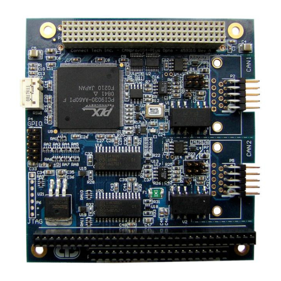
CANpro/104-Plus Opto User Manual CANpro/104-Plus Opto Diagrams Figure 1 illustrates the location of each component on the CANpro/104-Plus Opto. Figure 1: CANpro/104-Plus Opto Block Diagram www.connecttech.com CTIM-00052 Revision 0.00 4/23/2009 800-426-8979 | 519-836-1291... - Page 6 CANpro/104-Plus Opto User Manual Figure 2: CANpro/104-Plus Opto Board Diagram CTIM-00052 Revision 0.00 4/23/2009 www.connecttech.com 800-426-8979 | 519-836-1291...
-
Page 7: Hardware Installation
Support Center on the Connect Tech website for the latest product manuals, installation guides, diagnostic utilities and device driver software. Installing the CANpro/104-Plus Opto Into Your System Turn off the power to your embedded computer and open any enclosures needed to access the PC/104- Plus or PCI-104 expansion connectors. -
Page 8: Pci Interrupt, Clock And Id Selection
CANpro/104-Plus Opto User Manual PCI Interrupt, Clock and ID Selection The following PCI signals, (INTA#, INTB# INTC# INTD#), (CLK0, CLK1, CLK2, CLK3), (IDSEL0, IDSEL1, IDSEL2, IDSEL3), are selected by using the Rotary Switch on the CANpro/104-Plus Opto board (RSW1). Selections need to match the stack location of the CANpro/104-Plus Opto in your PC/104-Plus stack. -
Page 9: On-Board Jumper Configuration
CANpro/104-Plus Opto User Manual On-Board Jumper Configuration Figure 3: CAN Ports and Jumper Locations 120 Ohm Termination Jumpers Jumpers J1 and J4 will enable a 120 Ohm termination resistor across the CAN-H and CAN-L lines. Termination is always recommended for improved signal integrity, especially for long transmission lines. -
Page 10: Slew Rate Control Jumpers
CANpro/104-Plus Opto User Manual Figure 5: Example CANpro/104-Plus Opto in the middle of the CAN bus NOTE: The 120 Ohm termination jumper does not need to be installed in this situation. Slew Rate Control Jumpers Installing a jumper on J2 or J5 (see Figure 3) will disable slew rate limiting for the associated CAN port. -
Page 11: Connector Pinouts
CANpro/104-Plus Opto User Manual Connector Pinouts Table 2: DB-9 Cable Connector Pinouts Pin No. Signal CAN-L CAN GND (isolated or non) CAN GND (isolated or non) CAN-H Male DB-9 Connector Boards that are populated with right angled 2x5 0.100” headers will include a cable (CAG104) that will break out from the on-board 2x5 header to a DB-9 connector. -
Page 12: Software Configuration
Software Configuration The information provided below is intended for advanced users and developers that wish to create their own custom drivers. Typical CANpro/104-Plus Opto users will used the driver provided by Connect Tech. PCI Properties of CANpro/104-Plus Opto The CANpro/104-Plus Opto card will appear in your system with the following PCI information:... - Page 13 CANpro/104-Plus Opto User Manual Table 4: CAN Controller #1 (BasicCAN) OPERATING MODE RESET MODE READ WRITE READ WRITE 0x000 0x001 0x002 0x003 0x004 0x005 0x006 BTR0 BTR0 0x007 BTR1 BTR1 0x008 0x009 TEST TEST TEST TEST 0x00A TX Buffer Identifier Byte 1...
- Page 14 CANpro/104-Plus Opto User Manual Table 5: CAN Controller #2 (BasicCAN) OPERATING MODE RESET MODE READ WRITE READ WRITE 0x100 0x101 0x102 0x103 0x104 0x105 0x106 BTR0 BTR0 0x107 BTR1 BTR1 0x108 0x109 TEST TEST TEST TEST 0x10A TX Buffer Identifier Byte 1...
- Page 16 CANpro/104-Plus Opto User Manual Table 6: CAN Controller #1 (PeliCAN) Local OPERATING MODE RESET MODE Address READ WRITE READ WRITE 0x000 0x001 0x002 0x003 0x004 0x005 0x006 BTR0 BTR0 BTR0 0x007 BTR1 BTR1 BTR1 0x008 0x009 TEST TEST TEST TEST...
- Page 17 CANpro/104-Plus Opto User Manual Table 7: CAN Controller #2 (PeliCAN) Local OPERATING MODE RESET MODE Address READ WRITE READ WRITE 0x100 0x101 0x102 0x103 0x104 0x105 0x106 BTR0 BTR0 BTR0 0x107 BTR1 BTR1 BTR1 0x108 0x109 TEST TEST TEST TEST...
-
Page 18: Gpio Details
CANpro/104-Plus Opto User Manual CAN Controller Interrupts Each CAN controller is tied to a local interrupt on the PLX9030 which is then forwarded to a single interrupt on the PCI bus. Access to the PLX9030 interrupt control/status register can be done by accessing the INTCSR register at offset 4Ch from the PCI base address of the CANpro/104-Plus Opto. -
Page 19: Gpio Control And Addressing
CANpro/104-Plus Opto User Manual GPIO Control and Addressing GPIO pins on the CANpro/104-Plus Opto are controlled via the GPIOC register within the PLX 9030. The register is located at offset 0x54 from the PLX9030 PCI Base Address. The CANpro/104-Plus Opto ships with all GPIO pins set up as a data output pin by default. -
Page 20: Specifications
CANpro/104-Plus Opto User Manual Specifications Operating Environment Storage temperature: -40 C to 125 C Operating temperature: -40 C to 85 C Humidity: 95%, non-condensing Power Requirements +5 VDC @ 500mA (maximum) 380 mA (minimum) NOTE: External power output pins on each CAN port is limited up to 125 mA per port . -
Page 21: Certification
The CANpro/104-Plus Opto product family is to be included into a device ultimately subject to FCC, DOC/IC, and CE certification. The customer is responsible for bringing the completed device into compliance prior to resale. Connect Tech has designed CANpro/104-Plus Opto with EMI and EMC considerations such as: Ground and power planes Controlled slew-rate signals EMI/EMC reducing PCB layout www.connecttech.com... -
Page 22: Limited Lifetime Warranty
You may obtain warranty service by delivering this product to an authorized Connect Tech Inc. business partner or to Connect Tech Inc. along with proof of purchase. Product returned to Connect Tech Inc. must be pre-authorized by Connect Tech Inc. with an RMA (Return Material Authorization) number marked on the outside of the package and sent prepaid, insured and packaged for safe shipment.
Need help?
Do you have a question about the CANpro/104-Plus Opto and is the answer not in the manual?
Questions and answers