Table of Contents
Advertisement
Quick Links
Advertisement
Table of Contents

Related Manuals for Connect Tech CANpro/104


Summary of Contents for Connect Tech CANpro/104
- Page 1 USER MANUAL CANpro/104 CTIM-00043 (0.02) - January 15, 2010...
-
Page 2: Table Of Contents
CANpro/104 User Manual Table of Contents Copyright Notice ..............................4 Trademark Acknowledgement ..........................4 Revision History ..............................4 Introduction ................................ 5 Features................................5 Hardware Installation – Rev C & Later ......................6 Memory vs I/O Spaces ........................... 6 Memory Space ............................6 I/O Space .............................. - Page 3 CANpro/104 User Manual J3A ................................16 J3B ................................17 J3C ................................17 J4 and J5 ..............................17 Hardware Installation – Rev A & B ........................18 CANpro/104 Opto Diagrams ........................18 Interrupts and Memory I/O Range Selection ....................19 Interrupt Selection ........................... 19 Unique Interrupt Lines ..........................
-
Page 4: Copyright Notice
CANpro/104 User Manual Copyright Notice The information contained in this document is subject to change without notice. Connect Tech Inc. shall not be liable for errors contained herein or for incidental consequential damages in connection with the furnishing, performance, or use of this material. This document contains proprietary information that is protected by copyright. -
Page 5: Introduction
CANpro/104 User Manual Introduction CANpro/104 combines the power of two independent NXP SJA1000 CAN controllers with the compact size and rugged stability of PC/104. CANpro/104 is ideal for industrial control applications exposed to harsh conditions or environments. CANpro/104 Opto models feature 2.5 kV of data and power isolation. -
Page 6: Hardware Installation - Rev C & Later
CANpro/104 User Manual Hardware Installation – Rev C & Later The Connect Tech CANpro/104 board provides two (2) industry standard SJA1000 CAN Bus controllers in a PC/104 board format which supports both I/O and Memory mapping configurability. All the configuration options are setup with jumpers, identified as J1, J2, J3A, J3B, J3C, J4 and J5. -
Page 7: I/O Space
CANpro/104 User Manual I/O Space This region is supported by all PC/104 CPU System board vendors, and commonly consists of I/O Addresses from 0x000 to 0x3FF, although some System boards support I/O addresses beyond 0x3FF. (Note: Some I/O mapped PC/104 expansion boards only decode the lowest 10 bits of the I/O address, therefore these boards restrict the usable I/O space to 0x3FF). -
Page 8: Base Address Decoding
CANpro/104 User Manual Secondly, the Memory Space can be enabled by Application or Driver software, after the Operating system has started. This can be accomplished by writing a data value to an I/O Space Address which is decoded by the following J3B Jumper settings. Only one byte of the I/O Space is decoded at this I/O Address, and the location is Write Only. - Page 9 CANpro/104 User Manual X = Address bit is ignored (and the corresponding Jumper is Not Used). When Memory Space is selected, PC/104 Address bits 20 and 21 are always decoded as logical “0”. To determine which Jumpers to install and which to remove, the desired Address needs to be broken down into a binary number, all the Jumpers that correspond to “1-bits”...
-
Page 10: Pelican Vs Basiccan Addressing Modes
CANpro/104 User Manual PeliCAN vs BasicCAN Addressing Modes The SJA1000 can operate in 2 different modes, the PeliCAN mode which has extended features and additional registers and which consume 128 bytes of address space per device (there are 2 devices on this board). - Page 11 CANpro/104 User Manual Example #2: Memory Address 0x0C8000 (this address is below the 1-Meg boundary) 0x0C8000 = 0000.1100.100X.XXXX.CJJJ.JJJJ (binary) Address J3A or J3B Installed Value Position or Removed J3A-2 Removed J3A-3 Removed Address Bit always decoded as “0” Address Bit always decoded as “0”...
-
Page 12: Can Controller Addressing Table
CANpro/104 User Manual CAN Controller Addressing Table Once the Base Memory or I/O Address is setup, the 2 SJA1000 CAN controllers are accessed at the following address offsets. Offset from Base Address I/O Space Accessed Resource Memory Space BasicCAN mode PeliCAN mode 0x000 ... -
Page 13: Common Memory Space Address Selections
CANpro/104 User Manual Common Memory Space Address Selections Most System boards allow the PC/104 Bus stack to be allocated a portion of the memory address located in the 256K region of memory just below the 1-Meg address boundary (Addresses 0x0C0000 to 0x0FFFFF). Different BIOS’s allow different sized regions to the allocated. The CANpro/104 board requires 8K (8192 bytes) of memory space. -
Page 14: Performance Enhancement
CANpro/104 User Manual Performance Enhancement PC/104 Memory and I/O Bus cycles are typically about 700 nS long in total, but the access speed of the SJA1000 is considerably faster. The PC/104 Bus allows Memory and I/O Bus cycles to be shortened by the assertion of the SRDY* signal at the appropriate time in the Bus Cycle. -
Page 15: Single Interrupt Mode
CANpro/104 User Manual Single Interrupt Mode This mode routes the interrupt signal from both SJA1000 CAN controllers to one PC/104 Bus Interrupt signal. This mode is set up by installing Jumper J1/J2 Position “S” (either the CAN-0 or the CAN-1 “S” position can be used). When this jumper is installed, the Interrupt signal occurs on the “CAN-0 row”... -
Page 16: Security Id Feature
CANpro/104 User Manual Security ID Feature Some users may wish to associate the operation of their software with a particular hardware installation. To support this ability, an ID mechanism is available which uses a simple, somewhat unusual (but predictable) Write/Read mechanism by which software can determine that the CTI CANpro/104 board is installed. -
Page 17: J3B
CANpro/104 User Manual Function Position Jumper Installed Jumper Removed Mem Addr[16] or I/O Addr[9] = 1 Mem Addr[16] or I/O Addr[9] = 0 Mem Addr[15] or I/O Addr[8] = 1 Mem Addr[15] or I/O Addr[8] = 0 Mem Addr[14] = 1... -
Page 18: Hardware Installation - Rev A & B
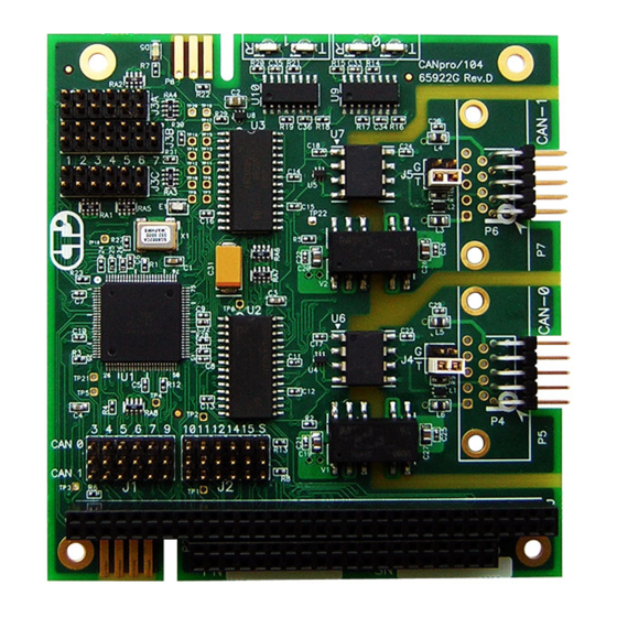
Download Zone of the Support Center on the Connect Tech website for the latest product manuals, installation guides, diagnostic utilities and device driver software. CANpro/104 Opto Diagrams Figure 1 shows the locations of various hardware components found on the CANpro/104. -
Page 19: Interrupts And Memory I/O Range Selection
CANpro/104 User Manual Interrupts and Memory I/O Range Selection CANpro/104’s interrupt lines and I/O ranges are jumper assignable. Interrupt Selection J1 and J2 are used for interrupt selection. Interrupt selection for the first CAN controller is achieved via the upper and centre rows of pins on the connector. The lower and center rows of pins allow selection of interrupts for the second CAN controller. -
Page 20: Address Mode And Range Selection
CANpro/104 User Manual Address Mode and Range Selection The first five jumper locations of jumper block J3 are used for board address selection. The first jumper location (Addr Mode) selects the number of address bits to use for the decoding of the board address. -
Page 21: Interrupt Sharing
CANpro/104 User Manual Interrupt Sharing Jumper block J3 also plays a part in the interrupt sharing. PC/104 supports the sharing of an interrupt between multiple cards. For example, two separate CANpro/104 cards are able to share the same interrupt across all four controllers. To accomplish interrupt sharing, the following steps must... -
Page 22: Ctim-00043 (0.01) 1/15/2010 Www.connecttech.com
CANpro/104 User Manual Other On-board Jumper Selection Near each I/O connector a 2x2 jumper block (either J4 or J5) will allow the configuration of both bus termination and slew rate limiting for the transceiver. J4 configures options for CAN controller 0, while J5 configures options for CAN controller 1. -
Page 23: Connector Pinouts
CANpro/104 User Manual Connector Pinouts Table 25: DB-9 Cable Connector Pinouts Pin No. Signal CAN-L CAN GND (isolated or non) CAN GND (isolated or non) CAN-H Male DB-9 Connector For boards populated with right angled 2x5 0.100” headers, cable CAG104 will break out from the onboard 2x5 header to a DB-9 connector. -
Page 24: Specifications
The CANpro/104 product family is to be included into a device ultimately subject to FCC, DOC/IC, and CE certification. The customer is responsible for bringing the completed device into compliance prior to resale. Connect Tech has designed CANpro/104 with EMI and EMC considerations such as: Ground and power planes... -
Page 25: Limited Lifetime Warranty
You may obtain warranty service by delivering this product to an authorized Connect Tech Inc. business partner or to Connect Tech Inc. along with proof of purchase. Product returned to Connect Tech Inc. must be pre-authorized by Connect Tech Inc. with an RMA (Return Material Authorization) number marked on the outside of the package and sent prepaid, insured and packaged for safe shipment.
Need help?
Do you have a question about the CANpro/104 and is the answer not in the manual?
Questions and answers