Table of Contents
Advertisement
Quick Links
Advertisement
Table of Contents

Related Manuals for Connect Tech FREE FORM/PCI-104 104


Summary of Contents for Connect Tech FREE FORM/PCI-104 104
-
Page 1: User Manual
FreeForm/PCI-104 User Manual Connect Tech, Inc. 42 Arrow Road Guelph, Ontario Canada, N1K 1S6 Tel: 519-836-1291 800-426-8979 Fax: 519-836-4878 Email: sales@connecttech.com support@connecttech.com URL: http://www.connecttech.com CTIM-00040 Revision 0.00 January 28, 2008... -
Page 2: Limited Lifetime Warranty
Connect Tech Inc. provides a Lifetime Warranty for all Connect Tech Inc. products. Should this product, in Connect Tech Inc.'s opinion, fail to be in good working order during the warranty period, Connect Tech Inc. will, at its option, repair or replace this product at no charge, provided that the product has not been subjected to abuse, misuse, accident, disaster or non Connect Tech Inc. -
Page 3: Customer Support Overview
Customer Support Overview If you experience difficulties after reading the manual and/or using the product, contact the Connect Tech reseller from which you purchased the product. In most cases the reseller can help you with product installation and difficulties. In the event that the reseller is unable to resolve your problem, our highly qualified support staff can assist you. -
Page 4: Table Of Contents
Connect Tech FreeForm/PCI-104 User Manual Table of Contents Limited Lifetime Warranty... 2 Copyright Notice ... 2 Trademark Acknowledgment ... 2 Customer Support Overview ... 3 Contact Information ... 3 Table of Contents ... 4 List of Tables... 5 List of Figures ... 5 Introduction ... -
Page 5: List Of Tables
Connect Tech FreeForm/PCI-104 User Manual List of Tables Table 1: FreeForm/PCI-104 Components ... 7 Table 2: Slot Selection (RSW1) ... 8 Table 3: FPGA Configuration Settings (J1) ... 8 Table 4: JTAG Programming Header Pinout (P2)... 9 Table 5: SPI Flash Programming Header Pinout (P3) ... 9 Table 6: RS-485 Port 1 Pinout (P5)... -
Page 6: Introduction
Connect Tech FreeForm/PCI-104 User Manual Introduction Connect Tech’s FreeForm/PCI-104 features Xilinx’s Virtex-5 multi-platform FPGA offering users a flexible, reconfigurable product that also takes advantage of the high bandwidth capabilities of the PCI bus while communicating with various I/O interfaces. Features PCI-104 form factor –... -
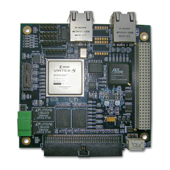
Page 7: Table 1: Freeform/Pci-104 Components
Connect Tech FreeForm/PCI-104 User Manual Figure 2: FreeForm/PCI-104 Layout Table 1: FreeForm/PCI-104 Components Connectors P5, P6 Jumpers /Switches RSW1 Components D1-D4 U12, U13 U15, U16 Revision 0.00 Description PCI-104 connector JTAG programming header SPI flash programming header RS-485 header GPIO header... -
Page 8: Table 3: Fpga Configuration Settings (J1)
Connect Tech FreeForm/PCI-104 User Manual Hardware Description and Configuration The following sections describe the function of all switches/jumpers and provide details on connector pinouts. Jumpers and Switches Slot Selection (RSW1) This rotary switch selects a slot position in the PCI-104 stack. When mounting on a PCI adapter card, ensure slot one is selected. -
Page 9: Table 5: Spi Flash Programming Header Pinout (P3)
Connect Tech FreeForm/PCI-104 User Manual Connector Pinouts PCI-104 Header (P1) Refer to PCI-104 specifications. Note: P1 must be connected to a PCI-104 stack supplying both 3.3V and 5V JTAG Programming Header (P2) Use P2 to configure the FPGA via JTAG. Refer to Power pins are for voltage reference only;... -
Page 10: Rs-485 Headers (P5, P6)
PCI / PCI-104 system. Table 8: External Power Connector Pinout (P8) It is recommended that a Connect Tech Inc. FreeForm/PCI-104 power supply is used. Orientation of the power supply connector is important. Ensure that the clip on the cable aligns with the catch on P8, as shown below. -
Page 11: Gpio Header (P7)
Connect Tech FreeForm/PCI-104 User Manual GPIO Header (P7) The GPIO header has been design such that when in differential mode, the positive (P) and negative (N) signals are adjacent on a standard ribbon cable. Note that the GPIO voltage level is set via hardware. -
Page 12: Hardware Installation
The FreeForm/PCI-104 ships with a CD containing drivers for various operating systems and example programs to help quickly develop applications. Refer to the CD for installation instructions. For other operating systems, please check the Connect Tech website’s download zone: http://www.connecttech.com/asp/Support/DownloadZone.asp Revision 0.00... -
Page 13: Fpga Configuration
Connect Tech FreeForm/PCI-104 User Manual FPGA Configuration To configure the FPGA via JTAG, connect the JTAG programming cable to signals align correctly. It is important to note that of Xilinx’s Parallel or USB programming cables. Launch Impact 1) Open iMPACT, and select create a new project 2) Select configure devices using boundary scan. - Page 14 Connect Tech FreeForm/PCI-104 User Manual 3) A prompt will ask for a new configuration file. Select the bitstream from the project directory. 4) A prompt will ask for a BSDL file for device number 2 (PLX PCI9056). Click Yes. 5) Browse to the bsdl folder and select PCI9056BA.bsd...
- Page 15 Connect Tech FreeForm/PCI-104 User Manual 6) iMPACT will add the device to the JTAG chain. 7) Again, a prompt will ask for device number three (National PHY). Browse to the bsdl folder and select DP83849IVS.bsd. The device will be added to the JTAG chain.
-
Page 16: Programming The Fpga
Connect Tech FreeForm/PCI-104 User Manual Programming the FPGA 1) Right click on device number one (Virtex-5 FPGA), and select program. The following diagram will appear. Note that verification will only work if an msk file has been created. 2) Select OK to begin programming. After programming is complete, the status window will report:... -
Page 17: Generating A Prom (Mcs) File
Connect Tech FreeForm/PCI-104 User Manual Generating a PROM (MCS) File 1) Double click Prom File Formatter in the Flows window. 2) The “Prepare PROM Files” dialog will appear. Ensure that the following settings are selected: Party SPI PROM MSC PROM File Format 3) Give the file a name, and click Next. - Page 18 Connect Tech FreeForm/PCI-104 User Manual 4) Select the PROM density (16M) 5) A prompt will ask to add device to data stream 0. Click OK. Select the bitstream from the project directory. Revision 0.00 click Next click Finish.
- Page 19 Connect Tech FreeForm/PCI-104 User Manual 6) Click “No” when asked if another device is to be added. Click “OK” to accept the setup. 7) Double Click “Generate File” from the “iMPACT” processes menu. The status will be reported in the console.
-
Page 20: Configuring The Fpga With The Spi Flash
Connect Tech FreeForm/PCI-104 User Manual Configuring the FPGA with the SPI Flash In previous Xilinx FPGA configurations, the SPI flash would require programming via 3 test software or through in-system methods. The following features are new to ISE 9.1/9.2, and are only available on select FPGAs, including the Virtex-5. - Page 21 Connect Tech FreeForm/PCI-104 User Manual 3) Browse to the directory containing the previously generated MCS file. Select and click “Open”. 4) The “FPGA SPI Flash Association” window will appear; select “M25P16” (this is the flash device connected to the FPGA).
-
Page 22: Programming The Flash
Connect Tech FreeForm/PCI-104 User Manual Programming the Flash 1) Right click the previously associated flash device, and select program. 2) The programming dialog will appear. Select “Verify” and “Erase Before Programming”, then click OK. Revision 0.00... - Page 23 Connect Tech FreeForm/PCI-104 User Manual 3) Observe the results in the transcript window. The SPI core is first download to the FPGA device The IDCODE is checked and verified Flash is erased Flash is programmed After completion of the flash programming, the FPGA will attempt to configure itself from the flash.
-
Page 24: Reference Design
Connect Tech FreeForm/PCI-104 User Manual Reference Design The FreeForm/PCI-104 ships with a pre-installed reference design. This reference design demonstrates how the FPGA interacts with the PLX 9056 PLX to local bus bridge. Functionality Local bus interface driven at 50MHz Slave access to:... -
Page 25: Implementation
Connect Tech FreeForm/PCI-104 User Manual Table 11: Local Address Space 1 (Bar 3) Local Address Contents 10000000 SPI Command 10000004 SPI Parameters 10000008 SPI Status 1000000C SPI Result 10000010 – Un addressable 100000FC 10000100 – Dual port memory RW 100001FC Implementation Refer to the FreeForm/PCI-104 VHDL Reference Design Application Note for further information. -
Page 26: Specifications
Connect Tech FreeForm/PCI-104 User Manual Specifications Programmable FPGA Input Clock Memory General Purpose User I/O 64 single ended I/O Serial Ethernet Operating Environment Power Requirements Dimensions Connectors Revision 0.00 Virtex-5 FPGA LX30T 100MHz 8MB Flash, 128MB DDR2-400 32 LVDS I/O...
Need help?
Do you have a question about the FREE FORM/PCI-104 104 and is the answer not in the manual?
Questions and answers