Moxa Technologies NPort IA5150 Series Quick Installation Manual
Hide thumbs
Also See for NPort IA5150 Series:
- Quick installation manual (7 pages) ,
- User manual (194 pages) ,
- Tech note (5 pages)

Related Manuals for Moxa Technologies NPort IA5150 Series


Summary of Contents for Moxa Technologies NPort IA5150 Series
- Page 1 NPort IA5150/5250 Series Quick Installation Guide Version 7.0, September 2021 Technical Support Contact Information www.moxa.com/support 2021 Moxa Inc. All rights reserved. P/N: 1802051500217 *1802051500217*...
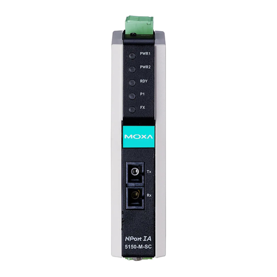
- Page 2 DR-120-24: 120W/5A DIN-rail 24 VDC power supply with 88 to 132 VAC/176 to 264 VAC input by switch Note: Notify your sales representative if any of the above items are missing or damaged. NPort IA5150 Series Appearance - 2 -...
- Page 3 NPort IA5250 Appearance Reset Button—Press the Reset button for 5 seconds to load factory defaults. Use a pointed object, such as a straightened paper clip or toothpick, to press the reset button. This will cause the Ready LED to blink on and off. The factory defaults will be loaded once the Ready LED stops blinking (after about 5 seconds).
- Page 4 Hardware Installation Procedure STEP 1: Connect the NPort IA to a network. Use a standard straight- through Ethernet cable to connect to a hub or switch. When setting up or testing the NPort IA, you might find it convenient to connect directly to your computer’s Ethernet port.
- Page 5 NOTE Wall mounting is certified for use in maritime applications. Software Installation Information For the NPort’s configuration, the default IP address of the NPort is: LAN: Static; IP = 192.168.127.254; netmask = 255.255.255.0. NOTE If you have forgotten the NPort's IP address, use the Device Search Utility (DSU) from your PC to locate the NPort.
- Page 6 4W/2W RS-485/RS-422 (Terminal Block) Pinouts RS-422/ RS-485 (2W) RS-485 (4W) – TxD+(B) – TxD-(A) Data+(B) RxD+(B) Data-(A) RxD-(A) – Four cables are available as optional accessories that can be used to connect the NPort IA to RS-232 serial devices. For your convenience, we show precise cable wiring diagrams for each of the two cables.
- Page 7 Female DB9 to Male DB25 Specifications Power Requirements Power Input 12 to 48 VDC Power Consumption • NPort IA-5150, NPort IA-5150-T, NPort IA- (Input Rating) 5250, NPort IA-5250-T: 12 to 48 VDC, 435 mA (max.) • NPort IA-5250I, NPort IA-5250I -T, NPort IA-5150-M-ST, NPort IA-5150-M-ST-T, MGate NPort IA-5150-M-SC, NPort IA-5150- M-SC-T:...
- Page 8 ATEX and IECEx Information NPort IA-5150/IA-5250 Series 1. Certificate number: DEMKO 18 ATEX 2168X 2. IECEx number: IECEx UL 18.0149X 3. Certification string: Ex nA IIC T4 Gc Ambient Range : 0°C ≤ Tamb ≤ 60°C (For suffix without -T) Ambient Range : -40°C ≤...
Need help?
Do you have a question about the NPort IA5150 Series and is the answer not in the manual?
Questions and answers