
Related Manuals for Moxa Technologies NPort IA-5150-M-SC


Summary of Contents for Moxa Technologies NPort IA-5150-M-SC
- Page 1 NPort IA5150/5250 Series User’s Manual Fourth Edition, September 2009 www.moxa.com/product © 2009 Moxa Inc. All rights reserved. Reproduction without permission is prohibited.
- Page 2 NPort IA5150/5250 Series User’s Manual The software described in this manual is furnished under a license agreement and may be used only in accordance with the terms of that agreement. Copyright Notice Copyright © 2009 Moxa Inc. All rights reserved. Reproduction without permission is prohibited.
-
Page 3: Table Of Contents
Table of Contents Chapter 1 Introduction....................1-1 Overview ..........................1-2 Package Checklist ......................1-2 Product Features......................... 1-3 Product Specifications......................1-3 Chapter 2 Getting Started..................2-1 Panel Layout........................2-2 Connecting the Hardware....................2-2 Wiring Requirements ....................2-3 Connecting the Power ..................... 2-3 Grounding the NPort IA5150/5250 Series .............. 2-4 Connecting to the Network .................. - Page 4 Accessible IP Settings ...................... 5-33 Auto Warning Settings ..................... 5-34 Auto warning: E-mail and SNMP trap..............5-34 Event Type ......................5-35 Monitor..........................5-38 Monitor Line ......................5-38 Monitor Async ...................... 5-38 Monitor Async-Settings ..................5-39 Monitor Relay Output ................... 5-39 Change Password ......................
-
Page 5: Chapter 1 Introduction
Introduction Chapter 1 Welcome to the NPort IA Series of industrial serial device servers. In this manual, we refer to the seven products in the series collectively as “NPort IA5150/5250 Series.” The sixteen models in the NPort IA5150/5250 Series are: 1. -
Page 6: Overview
NPort IA5150/5250 Series User’s Manual Introduction Overview The NPort IA5150/5250 series of device servers deliver easy and reliable serial-to-Ethernet connectivity for the industrial automation market. The NPort IA5150/5250 series is designed to allow any serial device to connect to an Ethernet network. The compact size of NPort IA device servers makes them an ideal choice for connecting RS-232/422/485 serial devices, such as PLCs, sensors, meters, motors, drives, barcode readers, and operator displays. -
Page 7: Product Features
NPort IA5150/5250 Series User’s Manual Introduction Product Features NPort IA5150/5250 Series device servers have the following features: Make your serial devices Internet ready Versatile socket operating modes, including TCP Server, TCP Client, UDP, and Real COM driver 2- or 4-wire RS-485 with patented ADDC™ (Automatic Data Direction Control) Slim type, inch-wide industrial strength casing DIN-Rail or wall mountable Built-in Ethernet cascading ports for easy wiring (RJ45 only) - Page 8 NPort IA5150/5250 Series User’s Manual Introduction RS-485 Data Direction Patented ADDC™ (Automatic Data Direction Control) Isolation 2 KV (5150I/5150I-M-SC/5150I-S-SC) NPort IA5250 Serial Interface Interface RS-232/422/485 No. of Ports Port Type Male DB9 Signals RS-232: TxD, RxD, RTS, CTS, DTR, DSR, DCD, RS-422: Tx+, Tx-, Rx+, Rx-, GND RS-485 (2-wire):...
- Page 9 NPort IA5150/5250 Series User’s Manual Introduction Power Requirements Power Input 12 to 48 VDC Alarm Contact Relay output with current carrying capacity of 1A @ 24 VDC Mechanical Casing IP30 protection Dimensions (W × H × D) 29 × 89.2 × 118.5 mm Gross Weight 5150 series: 0.15 kg (0.33 lb) 5250: 0.16 kg (0.35 lb)
-
Page 10: Chapter 2 Getting Started
Getting Started Chapter 2 In this chapter, we give instructions on installing NPort IA5150/5250 device servers. Software installation is covered in subsequent chapters. The following topics are covered: Panel Layout Connecting the Hardware Wiring Requirements Connecting the Power Grounding the NPort IA5150/5250 Connecting to the Network Connecting to a Serial Device LED Indicators... -
Page 11: Panel Layout
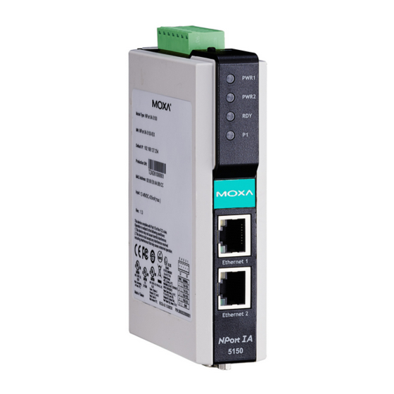
NPort IA5150/5250 Series User’s Manual Getting Started Panel Layout NPort IA5150 Series Top View Front View Bottom View PWR1 PWR2 Indicators Reset Reset Fiber optic RS-422/485 Ethernet RS-232 Dual power input 5150-M-SC and relay output NPort IA 5250 Top View Front View Bottom View PWR1... -
Page 12: Wiring Requirements
NPort IA5150/5250 Series User’s Manual Getting Started Wiring Requirements ATTENTION Safety First! Be sure to disconnect the power cord before installing and/or wiring your NPort IA5150/5250 Series. Wiring Caution! Calculate the maximum possible current in each power wire and common wire. Observe all electrical codes dictating the maximum current allowable for each wire size. -
Page 13: Grounding The Nport Ia5150/5250 Series
NPort IA5150/5250 Series User’s Manual Getting Started Grounding the NPort IA5150/5250 Series Grounding and wire routing helps limit the effects of noise caused by electromagnetic interference (EMI). Run the ground connection from the ground screw to the grounding surface prior to connecting devices. -
Page 14: Led Indicators
NPort IA5150/5250 Series User’s Manual Getting Started LED Indicators The top panels of all NPort IA5150/5250 have four LED indicators, as described in the following table. LED Name LED Color LED Function PWR1, PWR2 Power is being supplied to power input PWR1, PWR2. Steady on: Power is on and NPort IA is booting up. -
Page 15: Chapter 3 Initial Ip Address Configuration
Initial IP Address Configuration Chapter 3 When setting up your NPort IA5150/5250 for the first time, the first thing you should do is configure the IP address. This chapter introduces the methods that can be used to configure the device server’s IP address. Select one of the initial IP Address configuration methods to configure NPort IA5150/5250’s IP Address. -
Page 16: Initializing The Nport's Ip Address
NPort IA5150/5250 Series User’s Manual Initial IP Address Configuration Initializing the NPort’s IP Address 1. Determine whether your NPort IA5150/5250 needs to use a Static IP or Dynamic IP (either DHCP or BOOTP application). 2. If NPort IA5150/5250 is used in a Static IP environment, you can use NPort IA5150/5250 Administration Suite, ARP, Web Console, Telnet Console, or Serial Console to configure the new IP address. -
Page 17: Telnet Console
NPort IA5150/5250 Series User’s Manual Initial IP Address Configuration ATTENTION In order to use this setup method, both your computer and NPort IA5150/5250 must be connected to the same LAN. Or, you may use a cross-over Ethernet cable to connect the NPort IA5150/5250 directly to your computer’s Ethernet card. - Page 18 NPort IA5150/5250 Series User’s Manual Initial IP Address Configuration 1. From the Windows desktop, click on Start and then select Run. 2. Type telnet 192.168.127.254 (use the correct IP address if different from the default) in the Open text input box, and then click OK. 3.
- Page 19 NPort IA5150/5250 Series User’s Manual Initial IP Address Configuration 5. Type 1 to select IP address and then press Enter. 6. Use the Backspace key to erase the current IP address, type in the new IP address, and then press Enter.
- Page 20 NPort IA5150/5250 Series User’s Manual Initial IP Address Configuration 7. Press any key to continue… 8. Type m and then press Enter to return to the main menu.
-
Page 21: Serial Console (19200, N, 8, 1)
NPort IA5150/5250 Series User’s Manual Initial IP Address Configuration 9. Type s and then press Enter to Save/Restart the system. 10. Type y and then press Enter to save the new IP address and restart the NPort IA5150/5250. Serial Console (19200, n, 8, 1) You may use the RS-232 console port to set up the IP address for NPort IA5150/5250. - Page 22 NPort IA5150/5250 Series User’s Manual Initial IP Address Configuration Before you start to configure the NPort IA5150/5250 via serial console, turn off the power and connect the serial cable from NPort IA5150/5250 to your computer’s serial port. 1. Connect NPort IA5150/5250’s serial port 1 directly to your computer’s male RS-232 serial port.
- Page 23 NPort IA5150/5250 Series User’s Manual Initial IP Address Configuration 6. Press the “ ` ” key continuously and then power on the NPort IA5150/5250. 7. NPort IA5150/5250 will automatically switch from data mode to console mode as it receives a continuous string of “...
-
Page 24: Choosing The Proper Operation Mode
Choosing the Proper Operation Mode Chapter 4 In this chapter, we describe the various NPort IA5150/5250 operation modes. The options include an operation mode that uses a driver installed on the host computer, and operation modes that rely on TCP/IP socket programming concepts. After choosing the proper operation mode in this chapter, refer to Chapter 5 for detailed configuration parameter definitions. -
Page 25: Overview
NPort IA5150/5250 Series User’s Manual Choosing the Proper Operation Mode Overview NPort IA5150/5250 Serial Device Servers network-enable traditional RS-232/422/485 devices, in which a Serial Device Server is a tiny computer equipped with a CPU, real-time OS, and TCP/IP protocols that can bi-directionally translate data between the serial and Ethernet formats. Your computer can access, manage, and configure remote facilities and equipment over the Internet from anywhere in the world. -
Page 26: Tcp Server Mode
NPort IA5150/5250 Series User’s Manual Choosing the Proper Operation Mode ATTENTION The driver used for Real COM Mode comes with the NPort IA5150/5250 NPort Administrator. The driver is installed automatically on your computer when you install NPort IA5150/5250 Administration Suite. One of the major conveniences of using Real COM Mode is that Real COM Mode allows users to continue using RS-232/422/485 serial communications software that was written for pure serial communications applications. -
Page 27: Tcp Client Mode
NPort IA5150/5250 Series User’s Manual Choosing the Proper Operation Mode TCP Client Mode In TCP Client mode, the NPort IA5150/5250can TCP Client Mode actively establish a TCP connection to a pre-defined host computer when serial data arrives. After the data has been transferred, the NPort can automatically disconnect from the host computer by using the TCP alive check time or Inactivity TCP/IP... -
Page 28: Ethernet Modem Mode
NPort IA5150/5250 Series User’s Manual Choosing the Proper Operation Mode Ethernet Modem Mode Ethernet Modem Mode is designed for use with legacy operating systems, such as MS-DOS, that do not support TCP/IP Ethernet. By connecting one of NPort IA5150/5250’s serial port to the MS-DOS computer’s serial port, it is possible to use legacy software originally designed to transmit data via modem, but now transmit the data over the Ethernet. -
Page 29: Web Console Configuration
Web Console Configuration Chapter 5 The Web Console is the most user-friendly way to configure the NPort IA5150/5250 series products. This chapter will introduce the Web Console function groups and function definitions. This following topics are covered in this chapter: Opening Your Browser Basic Settings Network Settings... -
Page 30: Opening Your Browser
NPort IA5150/5250 Series User’s Manual Web Console Configuration Opening Your Browser 1. Open your browser with the cookie function enabled. (To enable your browser for cookies, right click on your desktop Internet Explorer icon, select Properties, click on the Security tab, and then select the three Enable options as shown in the figure below.) 2. - Page 31 NPort IA5150/5250 Series User’s Manual Web Console Configuration ATTENTION Refer to Chapter 3, “Initial IP Address Configuration,” to see how to configure the IP address. Examples shown in this chapter use the Factory Default IP address (192.168.127.254). The NPort IA5150/5250 homepage will open. On this page, you can see a brief description of the Web Console’s nine function groups.
-
Page 32: Basic Settings
NPort IA5150/5250 Series User’s Manual Web Console Configuration ATTENTION If your NPort IA5150/5250 application requires using password protection, you must enable the cookie function in your browser. If the cookie function is disabled, you will not be allowed to enter the Web Console Screen. Basic Settings Server name Setting... - Page 33 NPort IA5150/5250 Series User’s Manual Web Console Configuration Time zone Setting Factory Default Necessity User selectable time zone GMT (Greenwich Mean Time) Required Local time Setting Factory Default Necessity User adjustable time GMT (Greenwich Mean Time) Required (1900/1/1-2037/12/31) Click on the Modify button to open the Modify time settings window to input the correct local time.
-
Page 34: Network Settings
NPort IA5150/5250 Series User’s Manual Web Console Configuration ATTENTION If you disable both the “Web console” and “Telnet console,” you can still use NPort Administrator to configure NPort IA5150/5250 device servers either locally or remotely over the network. Refer to Chapter 6 for more details. Reset button protect Setting Factory Default... - Page 35 NPort IA5150/5250 Series User’s Manual Web Console Configuration Method Function Definition Static User defined IP address, Netmask, Gateway. DHCP DHCP Server assigned IP address, Netmask, Gateway, DNS, and Time Server DHCP/BOOTP DHCP Server assigned IP address, Netmask, Gateway, DNS, and Time Server, or BOOTP Server assigned IP address (if the DHCP Server does not respond) BOOTP...
- Page 36 NPort IA5150/5250 Series User’s Manual Web Console Configuration ATTENTION In Dynamic IP environments, the firmware will retry 3 times every 30 seconds until network settings are assigned by the DHCP or BOOTP server. The Timeout for each try increases from 1 second, to 3 seconds, to 5 seconds.
- Page 37 NPort IA5150/5250 Series User’s Manual Web Console Configuration Location Setting Factory Default Necessity 1 to 39 characters None Optional (E.g., Floor 1, office 2) Specify the location string for SNMP agents such as NPort IA5150/5250. This string is usually set to the street address where the NPort IA5150/5250 is physically located.
-
Page 38: Serial Settings
NPort IA5150/5250 Series User’s Manual Web Console Configuration Serial Settings Click on Serial Settings, located under Main Menu, to display serial port settings for ports 1 and To modify serial settings for a particular port, click on either Port 1 or Port 2 under Serial Settings, located under Main Menu on the left side of the browser window. - Page 39 NPort IA5150/5250 Series User’s Manual Web Console Configuration Baud rate Setting Factory Default Necessity 110 bps to 230400 bps 115200 bps Required Data bits Setting Factory Default Necessity 5, 6, 7, 8 Required When the user sets Data bits to 5 bits, the stop bits setting will automatically change to 1.5 bits. Stop bits Setting Factory Default...
-
Page 40: Operating Settings
NPort IA5150/5250 Series User’s Manual Web Console Configuration Operating Settings Click on Operating Settings, located under Main Menu, to display the operating settings for both of NPort IA5150/5250’s serial ports. Real COM Mode TCP alive check time Setting Factory Default Necessity 0 to 99 min 7 min... - Page 41 NPort IA5150/5250 Series User’s Manual Web Console Configuration Max connection Setting Factory Default Necessity 1, 2, 3, 4 Required Max connection is usually used when the user needs to receive data from different hosts simultaneously. The factory default is 1. In this case, only one specific host can access this port of the NPort IA5150/5250, and the Real COM driver on that host will have full control over the port.
- Page 42 NPort IA5150/5250 Series User’s Manual Web Console Configuration Packing length Setting Factory Default Necessity 0 to 1024 Optional Default = 0, The Delimiter Process will be followed, regardless of the length of the data packet. If the data length (in bytes) matches the configured value, the data will be forced out. The data length can be configured for 0 to 1024 bytes.
-
Page 43: Tcp Server Mode
NPort IA5150/5250 Series User’s Manual Web Console Configuration Force transmit Setting Factory Default Necessity 0 to 65535 ms 0 ms Optional 0: Disable the force transmit timeout. 1 to 65535: Forces the NPort IA5150/5250’s TCP/IP protocol software to try to pack serial data received during the specified time into the same data frame. - Page 44 NPort IA5150/5250 Series User’s Manual Web Console Configuration TCP alive check time Setting Factory Default Necessity 0 to 99 min 7 min Optional 0 min: TCP connection is not closed due to an idle TCP connection. 1 to 99 min: NPort IA5150/5250 automatically closes the TCP connection if there is no TCP activity for the given time.
- Page 45 NPort IA5150/5250 Series User’s Manual Web Console Configuration Ignore jammed IP Setting Factory Default Necessity No or Yes Optional Previously, when Max connections > 1, and the serial device is transmitting data, if any one of the connected hosts is not responding, it will wait until the data has been transmitted successfully before transmitting the second group of data to all hosts.
- Page 46 NPort IA5150/5250 Series User’s Manual Web Console Configuration Delimiter process Setting Factory Default Necessity Do nothing Delimiter + 1 Do Nothing Optional Delimiter + 2 Strip Delimiter [Delimiter + 1] or [Delimiter + 2]: The data will be transmitted when an additional byte (for Delimiter +1), or an additional 2 bytes (for Delimiter +2) of data is received after receiving the Delimiter.
-
Page 47: Tcp Client Mode
NPort IA5150/5250 Series User’s Manual Web Console Configuration Command port Setting Factory Default Necessity 1 to 65535 Optional The “Command port” is a listen TCP port for IP-Serial Lib commands from the host. In order to prevent a TCP port conflict with other applications, the user can set the Command port to another port if needed. - Page 48 NPort IA5150/5250 Series User’s Manual Web Console Configuration Inactivity time Setting Factory Default Necessity 0 to 65535 ms 0 ms Optional 0 ms: TCP connection is not closed due to an idle serial line. 0-65535 ms: NPort IA5150/5250 automatically closes TCP connection, if there is no serial data activity for the given time.
- Page 49 NPort IA5150/5250 Series User’s Manual Web Console Configuration Delimiter 1 Setting Factory Default Necessity 00 to FF None Optional Delimiter 2 Setting Factory Default Necessity 00 to FF None Optional Once the NPort IA5150/5250 receives both delimiters through its serial port, it immediately packs all data currently in its buffer and sends it to the NPort IA5150/5250 Ethernet port.
- Page 50 NPort IA5150/5250 Series User’s Manual Web Console Configuration The optimal Force transmit timeout depends on your application, but it must be at least larger than one character interval within the specified baud rate. For example, assume that the serial port is set to 1200 bps, 8 data bits, 1 stop bit, and no parity.
- Page 51 NPort IA5150/5250 Series User’s Manual Web Console Configuration Connection control Setting Factory Default Necessity Startup/None, Any Character/None, Any Character/Inactivity Time, DSR ON/DSR OFF, Startup/None Required DSR ON/None, DCD ON/DCD OFF, DCD ON/None The meaning of each of the above settings is given in the table below. In general, both the Connect condition and Disconnect condition are given.
-
Page 52: Udp Mode
NPort IA5150/5250 Series User’s Manual Web Console Configuration UDP Mode Packing length Setting Factory Default Necessity 0 to 1024 Optional Default = 0, The Delimiter Process will be followed, regardless of the length of the data packet. If the data length (in bytes) matches the configured value, the data will be forced out. The data length can be configured for 0 to 1024 bytes. - Page 53 NPort IA5150/5250 Series User’s Manual Web Console Configuration ATTENTION Delimiter 2 is optional. If left blank, then Delimiter 1 alone trips clearing of the buffer. If the size of the serial data received is greater than 1 KB, the NPort IA5150/5250 will automatically pack the data and send it to the Ethernet.
-
Page 54: Pair Connection Mode
NPort IA5150/5250 Series User’s Manual Web Console Configuration Destination IP address 1 Setting Factory Default Necessity IP address range Begin: Empty Required E.g., Begin: 192.168.1.1 End: Empty End: 192.168.1.10 Port: 4001 Destination IP address 2/3/4 Setting Factory Default Necessity IP address range Begin: Empty Optional... - Page 55 NPort IA5150/5250 Series User’s Manual Web Console Configuration TCP alive check time Setting Factory Default Necessity 0 to 99 min Required 7 min 0 min: TCP connection is not closed due to an idle TCP connection. 1 to 99 min: The NPort IA5150/5250 closes the TCP connection automatically if there is no TCP activity for the given time.
-
Page 56: Ethernet Modem Mode
NPort IA5150/5250 Series User’s Manual Web Console Configuration Ethernet Modem Mode Dial-in NPort IA5150/5250 listens for a TCP/IP connection request from the remote Ethernet modem or host. NPort IA5150/5250’s response depends on the ATS0 value, as outlined below. ATS0=0 (default): NPort IA5150/5250 will temporarily accept the TCP connection and then send the “RING”... - Page 57 NPort IA5150/5250 Series User’s Manual Web Console Configuration ATTENTION The “+++” command cannot be divided. The “+” character can be changed in register S2, and the guard time, which prefixes and suffixes the “+++” in order to protect the raw data, can be changed in register S12.
- Page 58 NPort IA5150/5250 Series User’s Manual Web Console Configuration AT Commands NPort IA5150/5250 supports the following common AT commands used with a typical modem: AT command Description Remarks Answer manully ATD<IP>:<Port> Dial up the IP address: Port No. ATE0=Echo OFF ATE1=Echo ON (default) ATH0=On-hook (default) ATH1=Off-hook ATI, ATI0, ATI1, ATI2...
-
Page 59: Reverse Telnet Mode
NPort IA5150/5250 Series User’s Manual Web Console Configuration S Registers AT command Description Remarks Ring to auto-answer (default=0) Ring counter (always=0) No action applied Escape code character (default=43 ASCII “+”) Return character (default=13 ASCII) Line feed character (default=10 ASCII) Backspace character (default= 8 ASCII) Wait time for dial tone (always=2, unit=sec) No action applied Wait time for carrier (default=3, unit=sec) -
Page 60: Disabled Mode
NPort IA5150/5250 Series User’s Manual Web Console Configuration TCP alive check time Setting Factory Default Necessity 0 to 99 min Optional Specifies the time slice for checking if the TCP connection is alive. If no response, NPort IA5150/5250 will disconnect the original connection. Inactivity time Setting Factory Default... -
Page 61: Accessible Ip Settings
NPort IA5150/5250 Series User’s Manual Web Console Configuration Accessible IP Settings NPort IA5150/5250 uses an IP address based filtering method to control access to itself. Accessible IP Settings allows you to add or block remote host IP addresses to prevent unauthorized access. -
Page 62: Auto Warning Settings
NPort IA5150/5250 Series User’s Manual Web Console Configuration Auto Warning Settings Auto warning: E-mail and SNMP trap Mail Server Mail server Setting Factory Default Necessity IP or Domain Name None Optional User name Setting Factory Default Necessity 1 to 15 characters None Optional Password... -
Page 63: Event Type
NPort IA5150/5250 Series User’s Manual Web Console Configuration ATTENTION Consult your Network Administrator or ISP for the proper mail server settings. The Auto warning function may not work properly if it is not configured correctly. NPort IA5150/5250 SMTP AUTH supports LOGIN, PLAIN, CRAM-MD5 (RFC 2554). SNMP Trap Server SNMP trap server IP or domain name Setting... - Page 64 NPort IA5150/5250 Series User’s Manual Web Console Configuration IP address changed The user has changed the NPort IA5150/5250’s IP address. When the IP address changes, the NPort IA5150/5250 will send an e-mail with the new IP address before the NPort IA150/5250 reboots.
- Page 65 NPort IA5150/5250 Series User’s Manual Web Console Configuration Ethernet2 link down NPort IA can provide system maintainers with real-time alarm messages. Even when control engineers are out of the control room for an extended period of time, they can still be informed of the status of devices almost instantaneously when exceptions occur.
-
Page 66: Monitor
NPort IA5150/5250 Series User’s Manual Web Console Configuration Trap Setting Factory Default Necessity Enable, Disable Disable Optional This feature helps the administrator manage how the NPort IA5150/5250 sends SNMP Trap to a pre-defined SNMP Trap server when the enabled events—such as Cold start, Warm start, Authentication failure, etc.—occur. -
Page 67: Monitor Async-Settings
NPort IA5150/5250 Series User’s Manual Web Console Configuration Monitor Async-Settings Click on Async Setting under Monitor to show the run-time settings for each of the four serial ports. Monitor Relay Output Click on Relay Output under Monitor to display the “Relay Output Status” for each of the report types (Power failure, Ethernet1 link down, etc.). -
Page 68: Load Factory Default
NPort IA5150/5250 Series User’s Manual Web Console Configuration ATTENTION If you forget the password, the ONLY way to configure NPort IA5150/5250 is by using the Reset button on NPort IA5150/5250’s casing to “Load Factory Default.” Remember to export the configuration file using NPort Administrator when you finish the configuration. -
Page 69: Configuring Nport Administrator
Configuring NPort Administrator Chapter 6 The following topics are covered in this chapter: Overview Installing NPort Administrator Configuration Broadcast Search Unlock Password Protection Configuring the NPort IA5150/5250 Upgrading the Firmware Export Configuration Import Configuration Monitor Port Monitor COM Mapping On-line COM Mapping Off-line COM Mapping IP Address Report... -
Page 70: Overview
NPort IA5150/5250 Series User’s Manual Configuring NPort Administrator Overview Device Server Administrator lets you install and configure your NPort IA5150/5250 Series products easily over the network. Five function groups are provided to ease the installation process, allow off-line COM mapping, and provide monitoring and IP location server functions. Device Server Administrator is an integrated software suite that bundles Device Server Administrator and the IP Serial Library, and provides everything you need to manage, monitor, and modify your NPort IA5150/5250 from a remote location. - Page 71 NPort IA5150/5250 Series User’s Manual Configuring NPort Administrator 2. Click on Next to install program files in the default directory, or select an alternative location. 3. Click on Next to install the program using the default program name, or select a different name.
- Page 72 NPort IA5150/5250 Series User’s Manual Configuring NPort Administrator 4. Click on Install to proceed with the installation. 5. The Installing window reports the progress of the installation.
- Page 73 NPort IA5150/5250 Series User’s Manual Configuring NPort Administrator 6. Click on Next to proceed with the installation. 7. Click on Finish to complete the installation of NPort IA5150/5250 Administration Suite.
-
Page 74: Configuration
NPort IA5150/5250 Series User’s Manual Configuring NPort Administrator Configuration The Administrator-Configuration window is divided into four parts. • The top section contains the function list and online help area. (Windows NT does not support this .chm file format.) • The five Administrator function groups are listed in the left section. •... -
Page 75: Broadcast Search
NPort IA5150/5250 Series User’s Manual Configuring NPort Administrator Broadcast Search The Broadcast Search function is used to locate all NPort IA5150/5250s that are connected to the same LAN as your computer. Since the Broadcast Search function searches by MAC address and not IP address, all NPort IA5150/5250s connected to the LAN will be located, regardless of whether or not they are part of the same subnet as the host. -
Page 76: Unlock Password Protection
NPort IA5150/5250 Series User’s Manual Configuring NPort Administrator 3. When the search is complete, the Broadcast Search window will close, and the NPort IA5150/5250s that were located will be displayed in the right pane of the Administrator window. If you found more than one server connected to this network, refer to the MAC address sticker on your server(s) to determine which server(s) are the ones you wish to configure. - Page 77 NPort IA5150/5250 Series User’s Manual Configuring NPort Administrator 1. Select the NPort IA5150/5250 with “Lock” status, click the right mouse button, and then select Unlock. 2. After inputting the correct password, the Administrator will display an “Unlock ok” message. 3. The “Lock” status will change to “Unlock,” and the Administrator utility will keep this NPort IA5150/5250 in the Unlock status throughout this Administrator session.
-
Page 78: Configuring The Nport Ia5150/5250
NPort IA5150/5250 Series User’s Manual Configuring NPort Administrator The meanings of the six “Status” states are given below (note that the term Fixed is borrowed from the standard fixed IP address networking terminology): Lock The NPort IA5150/5250 is password protected, “Broadcast Search” was used to locate it, and the password has not yet been entered from within the current Administrator session. - Page 79 NPort IA5150/5250 Series User’s Manual Configuring NPort Administrator 2. Unlock the NPort IA5150/5250 you wish to configure if it is password protected. Right click on the NPort IA5150/5250 and select Configure to start the configuration. 3. The progress bar shows that Administrator is retrieving configuration information from the specific NPort IA5150/5250.
-
Page 80: Upgrading The Firmware
NPort IA5150/5250 Series User’s Manual Configuring NPort Administrator 5. You will now be able to modify Time Zone, Local Date, Local Time, and Time Server. ATTENTION You can simultaneously modify the configurations of multiple NPort IA5150/5250s that are of the same model. To select multiple NPort IA5150/5250s, hold down the Ctrl key when selecting additional NPort IA5150/5250s, or hold down the Shift key to select a group of NPort IA5150/5250s. - Page 81 NPort IA5150/5250 Series User’s Manual Configuring NPort Administrator 2. Unlock the NPort IA5150/5250 you wish to configure if it is password protected. Right click on a specific NPort IA5150/5250 and select the Upgrade Firmware function to start upgrading the firmware. 3.
-
Page 82: Export Configuration
NPort IA5150/5250 Series User’s Manual Configuring NPort Administrator ATTENTION You can simultaneously upgrade the firmware of multiple NPort IA5150/5250s that are of the same model. To select multiple NPort IA5150/5250s, hold down the Ctrl key when selecting an additional NPort IA5150/5250, or hold down the Shift key to select a block of NPort IA5150/5250s. Export Configuration To export the configuration of an NPort IA5150/5250, right click on the NPort IA5150/5250, select Export Configuration, and then follow the onscreen instructions. -
Page 83: Import Configuration
NPort IA5150/5250 Series User’s Manual Configuring NPort Administrator Import Configuration The Import Configuration function is used to import an NPort IA5150/5250 configuration from a file into one or more of the same model NPort IA5150/5250. To import a configuration, first select the target servers, click the right mouse button, and then select Import Configuration. - Page 84 NPort IA5150/5250 Series User’s Manual Configuring NPort Administrator 2. Next, click on Monitor Add Target, select your targets from the list, and then click on Monitor Add Target Rescan 1. Click on Monitor under Function. 2. Click on Monitor Add Target from the menu bar, or click the right mouse button and select Add Target.
- Page 85 NPort IA5150/5250 Series User’s Manual Configuring NPort Administrator 3. Click on Rescan. 4. Select your targets from the list, and then click on OK. 6-17...
- Page 86 NPort IA5150/5250 Series User’s Manual Configuring NPort Administrator Once the Monitor function is running: 1. The NPort IA5150/5250 list will appear on the Monitor screen. 2. Right click the panel and select Settings. 3. Select or de-select Monitor Items. Use the single arrowhead buttons to move highlighted items from one box to the other.
- Page 87 NPort IA5150/5250 Series User’s Manual Configuring NPort Administrator 4. Select a Refresh Rate (the default is 3 seconds) on the General Settings page. 5. On the Advanced Settings page, select Display warning message for new event and/or Play warning music for new event. In the second case, you must enter the path to the WAV file that you want to be played.
- Page 88 NPort IA5150/5250 Series User’s Manual Configuring NPort Administrator 6. Right click in the NPort IA5150/5250 list section and select Go to start monitoring the NPort IA5150/5250. 7. For this example, the NPort IA5150/5250s shown in the list will be monitored. 8.
- Page 89 NPort IA5150/5250 Series User’s Manual Configuring NPort Administrator 9. In the Monitor screen, you can see that the NPort IA5150/5250s that are “Not Alive” are shown in red color. 10. If the NPort IA5150/5250 gets reconnected, a warning will be displayed to remind the user that the NPort IA5150/5250 is now “Alive.”...
-
Page 90: Port Monitor
NPort IA5150/5250 Series User’s Manual Configuring NPort Administrator Port Monitor The process described here is the same as in the previous “Monitor” section. The only difference is that you can select more items under Port Monitor than under Monitor. Select or de-select Monitor Items. Use the single arrowhead buttons to move highlighted items from one box to the other. -
Page 91: Com Mapping
NPort IA5150/5250 Series User’s Manual Configuring NPort Administrator COM Mapping Windows Administration Suite comes with Windows Real COM drivers. After you install NPort IA5150/5250 Administration Suite, there are two ways to set up the NPort IA5150/5250 serial port as your host’s remote COM port. The first way is with On-line COM Mapping. - Page 92 NPort IA5150/5250 Series User’s Manual Configuring NPort Administrator 3. Add the target to which you would like to map COM ports. 4. The NPort IA5150/5250 list that appears is the list generated by the previous Broadcast Search. Select the NPort IA5150/5250 to which you would like to map COM ports. 5.
- Page 93 NPort IA5150/5250 Series User’s Manual Configuring NPort Administrator 6. Select the COM Number. COM ports that are “In use” or “Assigned” will also be indicated in this drop-down list. If you select multiple serial ports or multiple NPort IA5150/5250s, remember to check the “Auto Enumerating”...
- Page 94 NPort IA5150/5250 Series User’s Manual Configuring NPort Administrator • To begin with, make sure there are some “PurgeComm()” functions being used in your application program. In this kind of situation, you might find that your NPort exhibits a much poorer operation performance than when using the native COM1 port. Once you have enabled the “Fast Flush”...
- Page 95 NPort IA5150/5250 Series User’s Manual Configuring NPort Administrator 8. The Serial Parameter settings shown here are the default settings when the NPort IA5150/5250 is powered on. However, the program can redefine the serial parameters to different values after the program opens the port via Win 32 API. 9.
- Page 96 NPort IA5150/5250 Series User’s Manual Configuring NPort Administrator 10. Select Discard Change to tell Administrator NOT to save the COM Mapping information to the host. 11. To save the configuration to a text file, select Export COM Mapping. You will then be able to import this configuration file to another host and use the same COM Mapping settings in the other host.
-
Page 97: Off-Line Com Mapping
NPort IA5150/5250 Series User’s Manual Configuring NPort Administrator Off-line COM Mapping 1. Add a target by inputting the IP address and selecting the Model Name without physically connecting the NPort IA5150/5250 to the network. 2. Modify the port settings as needed. 6-29... -
Page 98: Ip Address Report
NPort IA5150/5250 Series User’s Manual Configuring NPort Administrator 3. Right click in the NPort list section and select Apply Change. IP Address Report When the NPort IA5150/5250 is used in a dynamic IP environment, users must spend more time with IP management tasks. To make things easier, the NPort IA5150/5250 can periodically report its IP address to the IP location server, in case the address has changed. - Page 99 NPort IA5150/5250 Series User’s Manual Configuring NPort Administrator 2. Select the IP Address Report, and click the right mouse button to select Settings. 3. Configure the Local Listen Port to be the same as the NPort IA5150/5250’s “Auto report to UDP port”...
-
Page 100: Nport Ce Driver Manager For Windows Ce
NPort CE Driver Manager for Chapter 7 Windows CE The following topics are covered in this chapter: Overview Installing NPort CE Driver Manager Using NPort CE Driver Manager... -
Page 101: Overview
NPort IA5150/5250 Series User’s Manual NPort CE Driver Manager for Windows CE Overview NPort CE Driver Manager is designed for use with NPort 5000 serial ports that are set to Real COM mode. The software manages the installation of drivers that allow you to map unused COM ports on your PC to serial ports on the NPort 5000. - Page 102 NPort IA5150/5250 Series User’s Manual NPort CE Driver Manager for Windows CE 1. Go to Start Programs NPort CE Driver Manager. 2. Click on the COM Mapping page and then the “Search” button to scan for NPort servers.
- Page 103 NPort IA5150/5250 Series User’s Manual NPort CE Driver Manager for Windows CE 3. All NPort servers that were located will appear in the NPort CE Driver Manager window. Click on the server whose COM ports you would like to map to and then select the port index. Note that multiple selections are allowed.
- Page 104 NPort IA5150/5250 Series User’s Manual NPort CE Driver Manager for Windows CE 6. To configure the settings for a particular COM Port, select the row of the desired port, and then modify the setting in the “Settings” panel, as shown below. Tx Mode “Hi-Performance”...
-
Page 105: Ip Serial Lib
IP Serial LIB Chapter 8 The following topics are covered in this chapter: Overview IP Serial LIB Function Groups Example Program... -
Page 106: Overview
NPort IA5150/5250 Series User’s Manual IP Serial LIB Overview What is IP Serial Library? IP Serial Library is a Windows library with frequently used serial command sets and subroutines. IP Serial Library is designed to reduce the complexity and poor efficiency of serial communication over TCP/IP. -
Page 107: Ip Serial Lib Function Groups
NPort IA5150/5250 Series User’s Manual IP Serial LIB IP Serial LIB Function Groups Server Control Port Control Input/Output Data Port Status Miscellaneous Inquiry nsio_init nsio_open nsio_read nsio_lstatus nsio_break nsio_end nsio_close nsio_SetReadTimeouts nsio_data_status nsio_break_on nsio_resetserver nsio_ioctl nsio_write nsio_break_off nsio_checkalive nsio_flowctrl nsio_SetWriteTimeouts nsio_breakcount nsio_DTR nsio_RTS... -
Page 108: Appendix A Pinouts And Cable Wiring
Pinouts and Cable Wiring Appendix A In this appendix, we cover the following topics. Port Pinout Diagrams RS-232/422/485 (male DB9) Pinouts 4W/2W RS-485/RS-422 (Terminal Block) Pinouts Power Input and Relay Output Pinouts Cable Wiring Diagrams Serial Cables... -
Page 109: Port Pinout Diagrams
NPort IA5150/5250 Series User’s Manual Pinouts and Cable Wiring Port Pinout Diagrams RS-232/422/485 (male DB9) Pinouts 1 2 3 4 5 6 7 8 9 4W/2W RS-485/RS-422 (Terminal Block) Pinouts PIN RS-422/RS-485(4W) RS-485(2W) TxD+(B) TxD-(A) RxD+(B) Data+(B) RxD-(A) Data-(A) -
Page 110: Power Input And Relay Output Pinouts
NPort IA5150/5250 Series User’s Manual Pinouts and Cable Wiring Power Input and Relay Output Pinouts Shielded DC Power DC Power Relay output Relay output DC Power DC Power Ground input 1 input 1 input 2 input 2 Cable Wiring Diagrams Serial Cables Female DB9 to Male DB9 Male DB9... - Page 111 NPort IA5150/5250 Series User’s Manual Pinouts and Cable Wiring Female DB9 to Male DB25 Male DB9 Female DB9 Male DB25 Female DB25 RS-232 NPort IA Device Cable Wiring...
-
Page 112: Appendix B Well Known Port Numbers
Well Known Port Numbers Appendix B In this appendix, which is included for your reference, we provide a list of Well Known port numbers that may cause network problems if you set NPort IA5150/5250 to one of these ports. Refer to RFC 1700 for Well Known port numbers, or refer to the following introduction from the IANA. - Page 113 NPort IA5150/5250 Series User’s Manual Well Known Port Numbers (Login Host Protocol) (Login) TCP Socket Application Service Domain Name Server (domain) Finger protocol (Finger) World Wide Web HTTP Network News Transfer Protocol (NNTP) Network Time Protocol 160 – 223 Reserved for future use UDP Socket Application Service reserved...
- Page 114 SNMP Agents with MIB II & RS-232 Appendix C Like Group NPort IA5150/5250 has built-in SNMP (Simple Network Management Protocol) agent software. It supports SNMP Trap, RFC1317 RS-232 like group and RFC 1213 MIB-II. The following table lists the standard MIB-II group, as well as the variable implementation for the NPort IA5150/5250. RFC1213 MIB-II supported SNMP variables: System MIB Interfaces MIB...
- Page 115 NPort IA5150/5250 Series User’s Manual SNMP Agents with MIB II & RS-232 like group System MIB Interfaces MIB IP MIB ICMP MIB SysServices ifOutQLen ipAdEntNetMask IcmpOutTimestamps ifSpecific ipAdEntBcastAddr IcmpOutTimestampReps ipAdEntReasmMaxSize IcmpOutAddrMasks IpNetToMediaIfIndex IcmpOutAddrMaskReps IpNetToMediaPhysAddress IpNetToMediaNetAddress IpNetToMediaType IpRoutingDiscards UDP MIB TCP MIB SNMP MIB UdpInDatagrams tcpRtoAlgorithm...
- Page 116 NPort IA5150/5250 Series User’s Manual SNMP Agents with MIB II & RS-232 like group Address Translation MIB TCP MIB SNMP MIB snmpOutGetResponses snmpOutTraps snmpEnableAuthenTraps RFC1317: RS-232 MIB objects RS-232-like General Port RS-232-like Asynchronous Generic RS-232-like Group Table Port Group rs232Number rs232PortTable rs232AsyncPortTable rs232PortEntry...
-
Page 117: Appendix D Auto Ip Report Protocol
Auto IP Report Protocol Appendix D NPort device servers provide several ways to configure Ethernet IP addresses. One of them is DHCP Client. When you set up the NPort to use DHCP Client to configure Ethernet IP addresses, it will automatically send a DHCP request over the Ethernet to find the DHCP Server. And then the DHCP Server will send an available IP address to the NPort. - Page 118 NPort IA5150/5250 Series User’s Manual Auto IP Report Protocol And then you can develop your own programs to receive this information from the NPort. Here is NPort’s Auto IP Report Protocol. We provide an example for you to easily develop your own programs.
-
Page 119: Appendix E Compliance Notice
Compliance Notice Appendix E CE Warming This is a Class A product. In a domestic environment, this product may cause radio interference in which case the user may be required to take appropriate measures. Federal Communications Commission Statement FCC - This device complies with part 15 of the FCC Rules. Operation is subject to the following two conditions: (1) This device may not cause harmful interference, and (2) this device must accept any interference received, including interference that may cause undesired operation.
Need help?
Do you have a question about the NPort IA-5150-M-SC and is the answer not in the manual?
Questions and answers