
Related Manuals for Moxa Technologies IA3341


Summary of Contents for Moxa Technologies IA3341
- Page 1 IA3341 Hardware User’s Manual First Edition, May 2010 www.moxa.com/product © 2010 Moxa Inc. All rights reserved. Reproduction without permission is prohibited.
- Page 2 IA3341 Hardware User’s Manual The software described in this manual is furnished under a license agreement and may be used only in accordance with the terms of that agreement. Copyright Notice Copyright ©2010 Moxa Inc. All rights reserved. Reproduction without permission is prohibited.
-
Page 3: Table Of Contents
Table of Contents Introduction............................1-1 Overview ............................1-2 Model Descriptions and Package Checklist....................1-2 Product Features ..........................1-2 Product Hardware Specifications ......................1-3 Hardware Block Diagram ........................1-5 Hardware Introduction ........................2-1 Appearance............................2-2 LED Indicators............................2-3 Reset to Default Button ........................2-3 Real Time Clock..........................2-4 Placement Options ..........................2-4 DIN-Rail Mounting ........................2-4 Wall or Cabinet Mounting ......................2-5 Hardware Connection Description ..................... -
Page 4: Introduction
IA3341 is based on the MOXA ART ARM9 industrial processor, and features 2 RS-232/422/485 serial ports, dual LANs, 4 digital input channels, and 4 digital output channels. In addition, the IA3341 computer has 2 analog input channels and 2 thermocouple channels, making it the ideal solution for a variety of industrial applications, such as solar power and environmental monitoring. -
Page 5: Overview
The IA3341 is based on the MOXA ART ARM9 industrial processor, and features 2 RS-232/422/485 serial ports, dual LANs, 4 digital input channels, and 4 digital output channels. In addition, the IA3341 computer has 2 analog input channels and 2 thermocouple channels, making it the ideal solution for a variety of industrial applications. -
Page 6: Product Hardware Specifications
IA3341 Hardware User's Manual Introduction Product Hardware Specifications Computer CPU: MOXA ART ARM9 32-bit RISC CPU, 192 MHz OS (pre-installed): Embedded Linux DRAM: 64 MB onboard Flash: 16 MB onboard USB: USB 2.0 host x 1 (type A connector) Storage... - Page 7 IA3341 Hardware User's Manual Introduction Accuracy: • ±0.1% FSR @ 25°C • ±0.3% FSR @ 10°C and 60°C Sampling Rate: 12 samples/sec Input Impedance: 200K ohms Thermocouple Input Input Channels: 2 Sensor Types: J, K, T, E, R, S, B, N...
-
Page 8: Hardware Block Diagram
IA3341 Hardware User's Manual Introduction Hardware Block Diagram... -
Page 9: Hardware Introduction
The LED indicators allow users to monitor performance and identify trouble spots quickly, and the multiple ports can be used to connect a variety of devices. The IA3341 comes with a reliable and stable hardware platform that lets you devote the bulk of your time to application development. In this chapter, we provide basic information about the embedded computer’s hardware and its various components. -
Page 10: Appearance
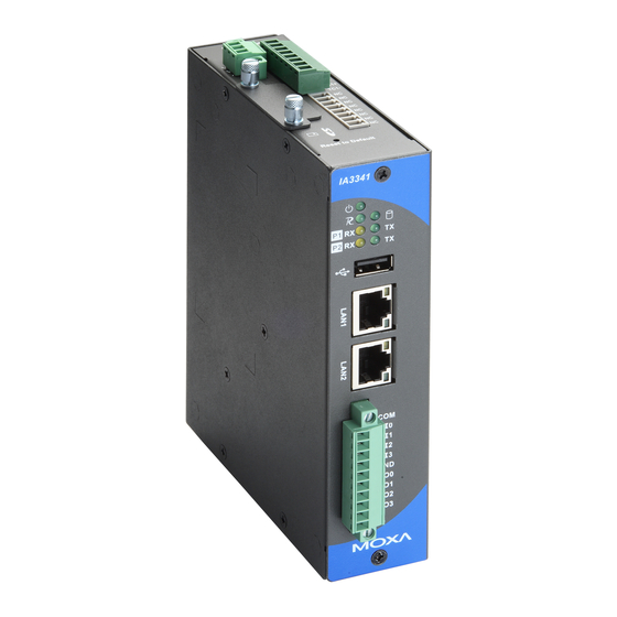
IA3341 Hardware User's Manual Hardware Introduction Appearance Front View System LED x 3 (Power, Ready, Storage) Serial LED x 4 (Tx, Rx) USB 2.0 Host x1 (type A) 10/100 Mbps LAN Port x2 (RJ45) DI x 4 DO x 4 Top &... -
Page 11: Led Indicators
IA3341 Hardware User's Manual Hardware Introduction Dimensions LED Indicators The IA3341 has 11 LED indicators on the front panel. Refer to the following table for information about each LED. LED Name Color Meaning Power Green Power is ON. No power is being received, or power error exists. -
Page 12: Real Time Clock
DIN-Rail Mounting The aluminum DIN-Rail attachment plate is already attached to the product’s casing. To attach the IA3341 to a DIN-Rail, make sure that the stiff metal spring is facing the top of the IA3341, as shown in the following figures. -
Page 13: Wall Or Cabinet Mounting
IA3341 Hardware User's Manual Hardware Introduction Wall or Cabinet Mounting The IA3341 comes with two metal plates for attaching it to a wall or the inside of a cabinet. STEP 1: Remove the aluminum DIN-Rail STEP 2: Mounting the IA3341 on the wall attachment plate from IA3341’s rear panel, and... -
Page 14: Hardware Connection Description
Hardware Connection Description This section describes how to connect the IA3341 to a network and various devices for first time testing purposes. The following topics are covered in this chapter: Wiring Requirements Connecting the Power Grounding the Unit ... -
Page 15: Wiring Requirements
Connecting the Power The IA3341 has a 3-pin terminal block for a 12 to 48 VDC power input. The following figures show how the power input interface connects to external power sources. If the power is properly supplied, the Power LED will light up. - Page 16 IA3341 Hardware User's Manual Hardware Connection Description ATTENTION This product is intended to be mounted to a well-grounded mounting surface, such as a metal panel. SG: The Shielded Ground (sometimes called Protect15-m1((Gro))-3(uc-10( n-8(ePro)ac1(m)1 -7(t)s1(m) the b-m1((tt)-7((...
-
Page 17: Connecting To A Serial Device
Connecting to a Serial Device Use properly wired serial cables to connect the IA3341 to serial devices. The serial ports of the IA3341 use male DB9 connectors. The ports can be configured by software for RS-232, RS-422, or 2-wire RS-485. The precise... -
Page 18: Digital Output Wiring
Connecting to the AI and Thermocouples The IA3341 has a 2-ch analog input and 2-ch thermocouple input. These channels are located on the top side of the unit in a terminal block. The pinouts for the AI and thermocouples are shown in the figure below. -
Page 19: Usb Hosts
4. When finished, use screws to attach the protective cover to the computer. ATTENTION The IA3341 does not support SD hot swap and PnP (Plug and Play) function. It is necessary to remove power source first before inserting or removing the SD card. -
Page 20: Regulatory Approval Statements
Regulatory Approval Statements This device complies with part 15 of the FCC Rules. Operation is subject to the following two conditions: (1) This device may not cause harmful interference, and (2) this device must accept any interference received, including interference that may cause undesired operation.
Need help?
Do you have a question about the IA3341 and is the answer not in the manual?
Questions and answers