Duerkopp Adler 510 Operating/Service Instructions Manual
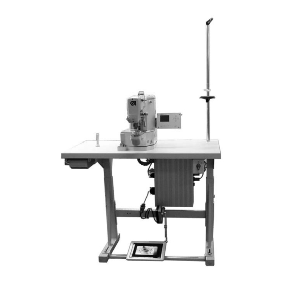
Cnc automat for bartacking seams and short seams
Hide thumbs
Also See for 510:
- Operating instructions manual (103 pages) ,
- Parts list (58 pages) ,
- Converting instructions (16 pages)
Table of Contents
Advertisement
Quick Links
CNC automat for bartacking seams
Postfach 17 03 51, D-33703 Bielefeld Ÿ Potsdamer Straße 190, D-33719 Bielefeld
Telefon +49 (0) 5 21/ 59 25-00 Ÿ Telefax +49 (0) 5 21/ 9 25 24 35 Ÿ www.duerkopp-adler.com
Ausgabe / Edition:
02/2006
Operating Instructions
Installation Instructions
Printed in Federal Republic of Germany
510
and short seams
Service Instructions
Teile-Nr.:/Part-No.: 0791 510001
1
2
3
Advertisement
Table of Contents

Related Manuals for Duerkopp Adler 510


Summary of Contents for Duerkopp Adler 510
-
Page 1: Operating Instructions
CNC automat for bartacking seams and short seams Operating Instructions Installation Instructions Service Instructions Postfach 17 03 51, D-33703 Bielefeld Ÿ Potsdamer Straße 190, D-33719 Bielefeld Telefon +49 (0) 5 21/ 59 25-00 Ÿ Telefax +49 (0) 5 21/ 9 25 24 35 Ÿ www.duerkopp-adler.com Ausgabe / Edition: 02/2006 Printed in Federal Republic of Germany... - Page 2 Summary Operating Instructions Installation Instructions Service Instructions Interconnection-diagram 9890 510001 B...
- Page 3 Foreword This instruction manual is intended to help the user to become familiar with the machine and take advantage of its application possibilities in accordance with the recommendations. The instruction manual contains important information on how to operate the machine securely, properly and economically. Observation of the instructions eliminates danger, reduces costs for repair and down-times, and increases the reliability and life of the machine.
-
Page 4: General Safety Instructions
General safety instructions The non-observance of the following safety instructions can cause bodily injuries or damages to the machine. 1. The machine must only be commissioned in full knowledge of the instruction book and operated by persons with appropriate training. 2. -
Page 5: Table Of Contents
Index Page: Part 3: Service Instructions Class 510 General notes ..........Arm shaft Preparatory work . - Page 6 Index Page: Material feed Gauge for reference position ........Reference position .
-
Page 7: General Notes
General notes The service instructions on hand describe the adjustment of the automatic bartacker 510. ATTENTION ! The operations described in the service instructions may only be carried out by qualified staff or other appropriately trained persons! Caution: Danger of injury ! In case of repair, alteration and maintenance work switch off main switch. -
Page 8: Arm Shaft
Arm shaft 2.1 Preparatory work Some of the adjustments at the arm shaft 1 can be carried out easier if the thread trimming mechanism 3 is removed before. Caution: Danger of injury ! Switch off main switch. Remove and mount thread trimming mechanism only when the automatic bartacker is switched off. -
Page 9: Assembly Of The Crank
2.2 Assembly of the crank Caution: Danger of injury ! Switch off main switch. Remove and mount crank only when the automatic bartacker is switched off. Standard The crank 4 has to be mounted on the arm shaft 1 in such a way that the pivot 3 of the screw 2 reaches into the drill-hole on the arm shaft. -
Page 10: Arm Shaft Position
2.3 Arm shaft position Caution: Danger of injury ! Switch off main switch. Check and adjust position of the arm shaft only when the automatic bartacker is switched off. Standard checking The arm shaft 1 should have no axial backlash, but it must not move too heavy. - Page 11 – Loosen screw at the motor coupling 7. – Push arm shaft cam 6 axially to the right as far as it will go. – Push adjusting ring 3 to the left against the bearing bush and tighten screws. – Check arm shaft with regard to axial backlash and smooth running.
-
Page 12: Bevel Gear For The Handwheel
2.4 Bevel gear for the handwheel Caution: Danger of injury! Switch off main switch. Check and adjust bevel gear only when the automatic bartacker is switched off. Standard checking The bevel gear 1 has to be positioned on the upper shaft in such a way that - when the handwheel 2 is engaged - there is as little clearance as possible between bevel gear 1 and bevel gear 3. -
Page 13: Adjust Bobbin Winder
2.5 Adjust bobbin winder Caution: Danger of injury! Switch off main switch. Check and adjust bobbin winder only when the automatic bartacker is switched off. Standard The bobbin winding operation must stop automatically when the bobbin is filled up to approx. 0.3 mm below the edge of the bobbin. Correction of the bobbin winder wheel –... -
Page 14: Thread Trimmer Cam
2.6 Thread trimmer cam Caution: Danger of injury! Switch off main switch. Check and adjust thread trimmer cam only when the automatic bartacker is switched off. Standard checking The correct position of the thread trimmer cam 1 is marked by a point on the upper shaft 2 and a line on the thread trimmer cam 1. -
Page 15: Crankshaft Drive To The Hook Shaft
2.7 Crankshaft drive to the hook shaft Caution: Danger of injury! Switch off main switch. Check and adjust crankshaft drive only when the automatic bartacker is switched off. Standard checking The arm shaft and the hook shaft are connected by the connecting rod 4 gripping into the crank 1 of the upper shaft. -
Page 16: Sewing Motor Coupling
2.8 Sewing motor coupling Caution: Danger of injury! Switch off main switch. Check and adjust sewing motor coupling only when the automatic bartacker is switched off. Standard checking Both coupling halves 1 and 2 must be positioned in such a way that the knobs of the cam 4 abut on the left or on the right. -
Page 17: Reference Position Of The Sewing Motor
2.9 Reference position of the sewing motor 2.9.1 Position of the initiator Caution: Danger of injury! Switch off main switch. Check and adjust initiator only when the automatic bartacker is switched off. Standard checking The distance between the initiator 1 and the largest outer diameter of the 180°... -
Page 18: Adjust Reference Position
2.9.2 Adjust reference position The adjustment of the correct reference position of the sewing motor is done with the help of the adjusting aid in the control. Call up adjusting aid The adjusting aid shows the correct position of crank 1. –... - Page 19 – Select menu “Test functions” with key “ò“. – Start menu with the key “OK”. The menu for the test functions appears. multitest Multitest 180°-disc 180° - Scheibe events Ereignisse DAC III DAC III init INIT – Select menu “180° disc” with the keys “ñ“ or “ò“. –...
- Page 20 Adjust 180° disc 180° - Scheibe – Loosen screw 3 at the 180° disc 4. – Turn crank 1 by hand into the position indicated in the display. – Place the front side of the 180° disc centrally on the initiator 5 in said position.
-
Page 21: Hook, Looping Stroke And Needle Bar Height
Hook, looping stroke and needle bar height 3.1 Driver shaft Caution: Danger of injury! Switch off main switch. Check and adjust driver shaft only when the automatic bartacker is switched off. Standard checking The driver shaft 4 should have no axial backlash, but it must not move too heavy. -
Page 22: Gear Segment On The Camshaft
3.2 Gear segment on the camshaft Caution: Danger of injury! Switch off main switch. Check and adjust gear segment only when the automatic bartacker is switched off. Standard checking The gear segment 3 should have no clearance on the camshaft 2, but it must not move too heavy. -
Page 23: Gear Segment To The Driver Shaft
3.3 Gear segment to the driver shaft Caution: Danger of injury! Switch off main switch. Check and adjust gear segment only when the automatic bartacker is switched off. Standard checking The gear segment 3 should grip into the toothed wheel 2 of the driver shaft with the smallest clearance possible, but it must not move too heavy. -
Page 24: Needle Bar Height
3.4 Needle bar height Caution: Danger of injury! Switch off main switch. Check and adjust needle bar height only when the automatic bartacker is switched off. Standard checking The needle bar 1 is provided with four notches as adjusting aid. The two notches on the higher position are for the needle system DPx5 (510-211/-212), those on the lower position are for the needle system DPx17 (520-213). -
Page 25: Distance Between Hook Tip And Needle
3.5 Distance between hook tip and needle Caution: Danger of injury! Switch off main switch. Check and adjust distance between hook tip and needle only when the automatic bartacker is switched off. Standard checking The hook tip 4 must stand as close as possible to the hollow groove of the needle, however, without touching it. -
Page 26: Looping Stroke And Needle Protection
3.6 Looping stroke and needle protection Caution: Danger of injury! Switch off main switch. Check and adjust looping stroke and needle protection only when the automatic bartacker is switched off. Standard checking The needle bar is provided with four notches as adjusting aid. The two notches on the higher position are for the needle system DPx5 (510-211/-212), those on the lower position are for the needle system DPx17 (520-213). -
Page 27: Thread-Guiding Parts
Thread-guiding parts 4.1 Thread controller spring Caution: Danger of injury! Switch off main switch. Check and adjust thread controller spring only when the automatic bartacker is switched off. Standard checking The adjustment standards for spring travel and spring tension refer to normal needle thread sizes. - Page 28 Correction of the spring tension – Loosen screw 1. – Pull out the complete tension unit. ATTENTION ! Make sure that the trip pin 5 does not fall out. – Loosen clamping screw 6. – Adjust thread tension regulator 3. In direction of rotation = higher tension In the opposite direction of rotation...
-
Page 29: Thread Regulator
4.2 Thread regulator Caution: Danger of injury! Switch off main switch. Check and adjust thread regulator only when the automatic bartacker is switched off. Standard checking The position of the thread regulator is dependent on the material thickness and the thread size. It has to be adjusted in such a way that the thread is guided around the hook in a controlled way. -
Page 30: Change Thread Wiper
4.3 Change thread wiper 4.3.1 General notes The built-in standard thread wiper is 50 mm long. The short thread wiper belonging to the accessories is 47 mm long. -
Page 31: Remove/Mount Thread Wiper
4.3.2 Remove/mount thread wiper ATTENTION: Danger of breakage ! When converting the automatic bartacker to thick fabrics change the thread wiper in any case. Caution: Danger of injury ! Switch off main switch. Change thread wiper only when the automatic bartacker is switched off. Remove thread wiper (standard thread wiper) –... -
Page 32: Thread Trimmer
Thread trimmer 5.1 Thread trimmer magnet Caution: Danger of injury! Switch off main switch. Check and adjust thread trimmer magnet only when the automatic bartacker is switched off. Standard checking The magnet 3 pushes the lever 5 with the roller bolt into the thread trimmer cam 6 by means of lever 1. -
Page 33: Position Of The Hook Knife
5.2 Position of the hook knife Caution: Danger of injury! Switch off main switch. Check and adjust position of the hook knife only when the automatic bartacker is switched off. Standard checking In resting position the point 2 of the hook knife 3 should stand on the left side of the stationary knife 1. -
Page 34: Cutting Pressure / Position Of The Stationary Knife
5.3 Cutting pressure / Position of the stationary knife Caution: Danger of injury! Switch off main switch. Check and adjust stationary knife only when the automatic bartacker is switched off. Standard checking The thread trimmer lever 2 should have a distance of 18.5 mm to the front edge of the throat plate 3. - Page 35 Correction Basic adjustment of thread trimmer lever 2 – Loosen screw 6. – Adjust a distance of 18.5 mm between thread trimmer lever 2 and the front of throat plate 3. – Tighten screw 6. Counter-knife – Screw out screws 7 and take off knife 5. –...
-
Page 36: Thread Guiding Sheet
5.4 Thread guiding sheet Caution: Danger of injury! Switch off main switch. Check and adjust thread guiding sheet only when the automatic bartacker is switched off. Standard checking The needle 3 should stand in the center of the cutout of thread guiding sheet 2. -
Page 37: Thread Trimmer
5.5 Thread tension lifting Caution: Danger of injury! Switch off main switch. Check and adjust the thread tension lifting only when the automatic bartacker is switched off. Standard checking The thread tension is opened during thread trimming. The tension release arm 6 actuates the presser bar 7 and opens the thread tension with the pressure pin. -
Page 38: Material Feed
Material feed 6.1 Gauge for reference position For setting the reference position the gauge shown above is required. The gauge cannot be ordered from Dürkopp Adler. – Make a gauge according to the above sketch. -
Page 39: Reference Position
6.2 Reference position Caution: Danger of injury! Switch off main switch. Check and adjust reference position with utmost caution when the automatic bartacker is switched on. Standard checking The movement of the clamping arm 2 and the rest plate 4 is effected by two step motors. - Page 40 – Screw on gauge 6 (see chapter 6.1) with the two screws 7 and 8. – Switch on main switch. The machine head positions in the machine zero position. – Move needle bar down by handwheel and check whether the needle points to the marking 9 on the gauge 6.
-
Page 41: Position Of The Fabric Clamps And The Rest Plate To The Needle
6.3 Position of the fabric clamps and the rest plate to the needle Caution: Danger of injury! Switch off main switch. Check and adjust rest plate only when the automatic bartacker is switched off. Standard checking The movement of the clamps 2 and 3 and the rest plate 1 is effected by two step motors. -
Page 42: Fabric Clamp Lifting
6.4 Fabric clamp lifting Caution: Danger of injury! Check and adjust the fabric clamp lifting with utmost caution when the automatic bartacker is switched on. Standard checking The fabric clamps should lift according to the material size. The lifting movements of the right 1 and the left 2 fabric clamp must be uniform. -
Page 43: Oil Lubrication
Oil lubrication Caution: Danger of injury ! Oil can cause skin eruption. Avoid a longer contact with the skin. Wash yourself thoroughly after a contact. ATTENTION ! The handling and disposal of mineral oils is subject to legal regulations. Deliver used oil to an authorized collecting station. Protect your environment. -
Page 44: Oil Circulation
7.1 Oil circulation From the filler pipe 1 the oil flows into the oil reservoir 2 and then it runs over into the oil reservoir 3. All lubricating points of the arm and head zone of the machine are provided with oil by the oil reservoir 2. The oil reservoir 3 supplies all lubricating points of the base plate. -
Page 45: Lubricating Oil Pump
7.2 Lubricating oil pump Caution: Danger of injury! Switch off main switch. Check and adjust lubricating oil pump only when the automatic bartacker is switched off. Standard checking The pump 3 sucks the oil contained in the oil pan 5 back into the upper oil reservoir via filter 4. -
Page 46: Exchange The Control Unit
Exchange the control unit See: Part 2, Installing instruction: “Sewing software installation”. Maintenance Caution: Danger of injury ! Switch off main switch. Maintenance work of the automatic bartacker must only be carried out when the machine is switched off. The daily or weekly maintenance work (cleaning and oiling) to be carried out by the operators of the automatic bartacker are described in the operating instructions (chapter 10).
Need help?
Do you have a question about the 510 and is the answer not in the manual?
Questions and answers