Table of Contents
Advertisement
Quick Links
Advertisement
Table of Contents

Related Manuals for TYAN FT77-B7015


Summary of Contents for TYAN FT77-B7015
- Page 1 ® TYAN FT77 B7015 Service Engineer’s Manual http://www.tyan.com...
- Page 2 http://www.tyan.com...
- Page 3 Corporation and has been reviewed for accuracy and reliability prior to ® printing. TYAN assumes no liability whatsoever, and disclaims any ® express or implied warranty, relating to sale and/or use of TYAN products including liability or warranties relating to fitness for a particular purpose or ® merchantability. TYAN retains the right to make changes to produce descriptions and/or specifications at any time, without notice.
- Page 4 There will be danger of explosion if battery is incorrectly replaced. Replace only with the same or equivalent type recommended by manufacturer. Dispose of used battery according to manufacturer instructions and in accordance with your local regulations. http://www.tyan.com...
- Page 5 About this Manual This manual provides you with instructions on installing your FT77-B7015. This Manual is intended for experienced users and integrators with hardware knowledge of personal computers. This manual is consisted of the following parts: Chapter1: Provides an introduction to the FT77-B7015 bare-...
- Page 6 SAFETY INFORMATION Before installing and using FT77-B7015, take note of the following precautions: ·Read all instructions carefully. ·Do not place the unit on an unstable surface, cart, or stand. ·Do not block the slots and opening on the unit, which are provided for ventilation.
-
Page 7: Table Of Contents
Table of Contents Chapter 1: Overview ..............9 ® 1.1 About the TYAN FT77-B7015..........9 1.2 Product Models..............10 Features ................11 1.4 Standard Parts List ..............13 1.4.1 Box Contents ..............13 1.4.2 Accessories ..............15 1.5 Optional Parts................16 1.6 About the Product..............17 1.6.1 System Front View ............17 1.6.2 System Rear View ............17... - Page 8 M1801F77-Fan Board Features ........59 3.8.2 M1801F77 Fan Board Connector Pin Definition...60 Removing the Motherboard ..........61 Appendix I: BIOS Differences.............63 Appendix II: Installing the Internal 3.5”HDD......65 Appendix III: Cable Connection Tables ........67 Appendix IV: FRU Parts Table ............69 Appendix V: Technical Support ..........71 http://www.tyan.com...
-
Page 9: Chapter 1: Overview
6 channels with 18 DDR3 DIMMs, providing a rich feature set and ® incredible performance. Leveraging advanced technology from Intel FT77-B7015 server system is capable of offering scalable 32 and 64-bit computing, high-bandwidth memory design, and lightning-fast PCI-E bus implementation. FT77-B7015 not only enpowers your company in today’s demanding IT environment but also offers a smooth path for future application usage. -
Page 10: Product Models
1.2 Product Models Model HDD Bays Power supply Support 2 internal 2.5” 3600W(1200Wx3) PWR B7015F77V2R SATAII HDD supply http://www.tyan.com... -
Page 11: Features
1.3 Features ® TYAN FT77B7015 (B7015F77V2R [BTO]) Form Factor 4U Rackmount Chassis Model FT77 Dimension (D x W x 31.31" x 17.24" x 6.93" (770 x 438 x 176mm) System Motherboard S7015-CA Board Dimension 16"x19" (406.4x482.6mm) Gross Weight 29 kg... - Page 12 Please refer to our OS supported list. System FCC (DoC) Class A Regulation CE (DoC) Operating Temp. 5° C ~ 55° C (41° F~ 131° F) Operating Non-operating Environment - 40° C ~ 70° C (-40° F ~ 158° F) Temp. http://www.tyan.com...
-
Page 13: Standard Parts List
RoHS 6/6 Complaint Yes Barebone (1) FT77B7015 Barebone Package Manual (1) User's manual Contains ® Installation CD (1) TYAN installation CD 1.4 Standard Parts List This section describes FT77-B7015 package contents accessories. Open the box carefully and ensure that all components are present and undamaged. - Page 14 120 x120 x38 MM Fan M1008 Front LED control Board_R03 M7015 Rear I/O Board_R02 M7015-PBP PWR Backplane Board_R01 M7015-PDB PWR Distribution board for PCI-E Card_R02 M1801F77-FB Fan Board http://www.tyan.com...
-
Page 15: Accessories
If any items are missing or appear damaged, contract your retailer ® or browse to TYAN ’s website for service: http://www.tyan.com. ® The Web site also provides information on other TYAN products, plus FAQs, compatibility lists, BIOS settings, and more. ® 1 x TYAN... -
Page 16: Optional Parts
1.5 Optional Parts Model Item Picture Quantity Description Number HDD Bracket CHDT-0150 3.5" HDD Bracket http://www.tyan.com... -
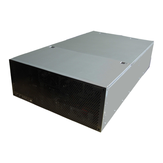
Page 17: About The Product
The following views show you the product. 1.6.1 System Front View USB ports ID button Power button (with LED) Warning LED NMI button HDD LED Reset button 1.6.2 System Rear View VGA Port ID LED Power supply Expansion slots USB Port LAN Port http://www.tyan.com... -
Page 18: Led Definitions
Press ID button when the system is AC (Alternating Current) on, then ID LED will show the system is identified with emitting blue light. Users from remote site could also activate ID LED by input a few commands in IPMI, detailed software support please visit for latest AST2050 user guide. http://www.tyan.com http://www.tyan.com... -
Page 19: Motherboard Layout
1.6.4 Motherboard Layout The diagram is representative of the latest board revision available at the time of publishing. The board you receive may not look exactly like the above diagram. http://www.tyan.com... -
Page 20: Jumpers & Connectors
1.6.5 Jumpers & Connectors Jumper/Connector Function CN17/CN20 COM port CN18 Board-to-Board Receptacle connector CN19 USB header CN43 Front Panel header CN36/CN37/CN40 FAN connector CN101 Clear CMOS CN61 System Intrusion header CN73 NMI button header CN74 ID button header http://www.tyan.com... - Page 21 Jumper Placement CN40 CN43 CN19 CN20 CN37 CN36 CN18 CN17 CN43: Front Panel header Signal PW_LED+ PW_LED- WLED+ HDD_LED+ PWR_SW# P3V3_SB RST_SW# Pin_1 http://www.tyan.com...
- Page 22 USB1+ HSYNC USB2- VSYNC USB2+ DDC_DATA USB3- DDC_CLK USB3+ Vcc5_VGA Vcc_USB Vcc_USB Vcc_USB Vcc_USB Vcc_USB Vcc_USB CN19: USB header Signal VCC_USB USB6- USB6+ VCC_USB USB7- USB7+ Pin_1 CN36/ CN37/ CN40: FAN connector Signal GND P12V TACH PWM GND P12V http://www.tyan.com...
- Page 23 Put jumper cap back to Pin_1 and Pin_2 (default setting) Use jumper cap to close Pin_2 and Pin_3 Pin_3 Pin_1 for several seconds to Clear CMOS Clear CMOS Reconnect power and power on system CN61: System Intrusion header Signal INTRUDER_N Pin_1 http://www.tyan.com...
- Page 24 CN73: NMI button header Signal FP_NMI_N Pin_1 CN74: ID button header Signal ID_BUTTON_N Pin_1 http://www.tyan.com...
-
Page 25: System Block Diagram
1.6.6 System Block Diagram S7015 Block Diagram http://www.tyan.com... -
Page 26: Internal View
⑦ ③ S7015-CA Main Board Power Cage ① ⑤ M7015-PDB_R02 M7015-PBP_R01 ② ⑥ PWR Distribution board PWR Backplane Board M1008_R03 Two 2.5 inch dual HDD Bracket ③ ⑦ Front LED control Board System Fans PCI-E Slot Shield ④ ⑧ http://www.tyan.com... -
Page 27: Chapter 2: Setting Up
Most of the electrical and mechanical connections can be disconne- -cted using your fingers. It is recommended that you do not use nee- -dlenosed pliers to remove connectors as these can damage the soft metal or plastic parts of the connectors. http://www.tyan.com... -
Page 28: Precautions
Components and electronic circuit boards can be damaged by discharges of static electricity. Working on a system that is connected to a power supply can be extremely dangerous. Follow the guidelines below to avoid damage to FT77-B7015 or injury to yourself. ... -
Page 29: Installing Motherboard Components
CPUs, memory modules and add on cards. 2.1.1 Removing the Chassis Cover Follow these instructions to remove FT77-B7015 chassis cover. Thumb two screws on the back side as show in the small diagram. Then slide the top cover out. - Page 30 3. Here is the overview after the chassis cover was removed. http://www.tyan.com...
-
Page 31: Installing The Cpu And Heat Sink
2.1.2 Installing the CPU and Heat sink Follow the steps below on installing CPUs and CPU heat sinks. 1. Locate the CPU socket. 2. Press the lever and unlock the CPU socket. http://www.tyan.com... - Page 32 3. Lift the CPU protection cap up and lay the CPU into the socket(A), ensuring pin1 is correctly located(B); 4. Close the socket cover and press the CPU lever down to secure the CPU; http://www.tyan.com...
- Page 33 5. Place the heatsink on top of the CPU and secure it with 4 screws. http://www.tyan.com...
-
Page 34: Installing The Memory
Press the memory slot locking levers in the direction of the arrows as shown in the following illustration. Align the memory module with the slot. When inserted properly, the memory slot locking levers lock automatically onto the indentations at the ends of the module. http://www.tyan.com... - Page 35 2). Refer to the memory population option table for recommended memory installation instruction. 3). “√”indicates a populated DIMM slot. Memory Population Option Table ® To achieve the best performance, TYAN strongly recommended memory installation configuration as listed below: Single CPU installed (CPU0 Only) Quantity of memory...
- Page 36 CPU1 DIMMA 1 √ √ CPU1 DIMMA 2 √ CPU1 DIMMB 0 √ √ √ CPU1 DIMMB 1 √ √ CPU1 DIMMB 2 √ CPU1 DIMMC 0 √ √ √ CPU1 DIMMC 1 √ √ CPU1 DIMMC 2 √ http://www.tyan.com...
-
Page 37: Installing Expansion Cards
2.1.4 Installing Expansion Cards FT77-B7015 has eight expansion slots which can support GPU (Graphic Processing Unit) card. Follow these instructions to install expansion cards. 1. Locate the expansion slot on the motherboard, unscrew the bracket from the slot you want to use. - Page 38 4. Connect the cables between the expansion card and the power distribution board, the connectors you use should match with the slot you add the card with. 5. Here is the end of the add on card installation. http://www.tyan.com...
-
Page 39: Installing Hard Drives
2.1.5 Installing Hard Drives The FT77-B7015 supports four internal 2.5” SATAII hard disks. Each bracket could be installed with two hard disks. Follow these instructions to install a hard drive. Unscrew the 2.5’’ bracket out from the chassis, place a 2.5’’... -
Page 40: Rack Mounting
Rail with Bracket x 2 Mounting Ears x 2 Screw Sack x 1 2.2.1 Installing the Server in a Rack Follow these instructions to mount the FT77-B7015 into an industry standard 19” rack. Note: Before mounting FT77-B7015 in a rack, ensure that all internal components have been installed and that the unit has been fully tested. -
Page 41: Installing The Inner Rails To The Chassis
Screw the mounting ear to each side of FT77 as shown using 3 screws from the supplied screws kit. Push the latch key and draw out the inner rails from sliding rails. Secure inner rails to both sides of the chassis, be sure the five mounting holes are correctly matched. http://www.tyan.com... -
Page 42: Installing The Outer Rails To The Rack
4 M5 x 10 screws with washer for each side. 2.2.4 Rack mounting the Server 1. Draw out the middle rail till the latch position. 2. Lift the chassis and then insert the inner slide rails into the middle rails. http://www.tyan.com... - Page 43 3. Push the chassis in and pull the latch key (A). Then push the whole system into the rack (B). 4. Secure the mounting ears of chassis to the rack with 2 M5 x 13 screws. http://www.tyan.com...
- Page 44 http://www.tyan.com...
-
Page 45: Chapter 3: Replacing Pre-Installed Components
M7015 power backplane, system fan, power cage etc. Disassembly Flowchart The following flowchart outlines the disassembly procedure. Chassis Cover Power Supply x 3 M1008 Front Panel Board M7015-PDB System Fan M7015-PBP M1801F77-Fan Board Power Cage M7015 I/O board System mainboard http://www.tyan.com... -
Page 46: Removing The Cover
Removing the Cover Before replacing any parts you must remove the chassis cover. Follow Chapter 2.1.1 to remove the cover of FT77-B7015. Replacing the Power Supply 3.4.1 Replace the power supply To replace the power supply follow these instructions. Press the tab as shown in the diagram and pull out the power. -
Page 47: Replacing M7015 Power Distribution Board
3.4.2 Replacing M7015 Power Distribution Board 1. Remove the 2 screws securing M7015-PDB_R02 to the bracket. 2. Renew the M7015-PDB and fix it to the chassis following the step in reverse. http://www.tyan.com... -
Page 48: M7015 Power Distribution Board Features
3.4.3 M7015 Power Distribution Board Features 17 Power Connectors (2x4 pin ) for PCI-E add on card & System fan Power Connector (Connect to M7015-PBP PWR backplane) http://www.tyan.com... -
Page 49: Replace The M7015 Power Backplane
1. Lift out the M7015-PBP_R01 bracket after pulling out the power Supplies and M7015-PDB. 2. Remove the 4 screws securing M7015-PBP to the bracket. 3. Renew the M7015-PBP and fix it to the chassis following the steps in reverse. http://www.tyan.com... -
Page 50: M7015 Power Backplane Features
3.4.5 M7015 power backplane Features M7015-PBP Power backplane support FT77-B7015 with EMERSON DC1200-3 power supply. On board PWR Connector * 3 (Vertical, connect to PWR supply) PWR Connector (Right angle, connect to MB) PWR Connector (Vertical, connect to M7015-PDB PWR distribution board) http://www.tyan.com... -
Page 51: Replacing M7015 I/O Board
After remove power supplies and M7015 PBP, you can replace the M7015 I/O board_R02 follow these instructions. Remove the power cage from the chassis with four screws. Lift the power cage out of the chassis and locate the M7015 I/O board. http://www.tyan.com... - Page 52 Unscrew M7015 I/O board with its bracket and carefully pull it Renew the M7015 I/O board and fix it to the chassis following the step in reverse. USB Port VGA Port http://www.tyan.com...
-
Page 53: Replacing The Led Control Board
Follow these instructions to replace the M1008 LED control board_R03. Unplug the cables from the connectors on M1008 and main board. A: From M1008 B: From S7015 Remove the three screws securing the LED control board unit to the chassis. http://www.tyan.com... -
Page 54: M1008 Led Control Board Features
3. Renew the board and place it back to the chassis following the above procedures in reverse. 3.6.1 M1008 LED Control Board Features http://www.tyan.com... - Page 55 M1008 LED Control Board Connector Pin Definition J1: USB Header Definition Definition USB1- USB2- USB1+ USB2+ J3: SSI Definition Definition PW_LED+ ID_LED+ PW_LED- ID_LED- HD/LAN3 LED+ SYS_FAULT1- HD/LAN3 LED- SYS_FAULT2- PWR_SW+ LAN1_LED+ PWR_SW- LAN1_LED- RESET+ ICH_SMBDAT RESET- ICH_SMBCLK ID_SW+ INTRU# TEMP_SENSER LAN2_LED+ EXT_INT LAN2_LED- http://www.tyan.com...
-
Page 56: Replacing The System Fan
3.7 Replacing the System Fan 1. Lift the fan which you need to replace up. 2. Reinsert a new fan. http://www.tyan.com... -
Page 57: Replacing The M1801F77-Fan Board
Replacing the M1801F77-Fan Board 1. Remove the four screws securing the fan holder. 2. Disconnect system fan cables from the chassis. 3. Lift the fan holder up and turn it upside down, remove the ten screws. http://www.tyan.com... - Page 58 4. Renew the board and tighten the screw place it back to the chassis following the above procedures in reverse. http://www.tyan.com...
-
Page 59: M1801F77-Fan Board Features
3.8.1 M1801F77-Fan Board Features http://www.tyan.com... -
Page 60: M1801F77 Fan Board Connector Pin Definition
J1~J6: 4 pin Fan connector Definition Definition VDD+12V TACK PW1/PW2/PW3: Big 4 pin Power connector Definition Definition VDD+12V VCC+5V J7: fan signal control Definition Definition J8: fan control header Definition Definition TACH1 TACH2 TACH3 TACH6 TACH4 TACH5 PWR2 PWR1 PWR3 http://www.tyan.com... -
Page 61: Removing The Motherboard
Remove the 15 screws securing the motherboard to the chassis. Carefully lift the motherboard from the chassis as S7015-CA is too large to lift straight out .Lift the front edge of the board to an angle of about 45 then slides the whole board out. http://www.tyan.com... - Page 62 http://www.tyan.com...
-
Page 63: Appendix I: Bios Differences
Appendix I: BIOS Differences The BIOS for FT77-B7015 is similar to S7015-CA while there are some differences in menus. The following table displays those differences in details. You can select item Hardware Health Configuration in the Advanced Settings to configure Auto Fan Control Function. - Page 64 Change Option 03 VBattary : x.xxx V Select Field 22 FAN1 : xxxx RPM General Help 23 FAN2 : xxxx RPM Save and Exit 24 FAN3 : xxxx RPM Exit Read only. It can not be modified in user mode. http://www.tyan.com...
-
Page 65: Appendix Ii: Installing The Internal 3.5"Hdd
Appendix II: Installing the Internal 3.5”HDD Considering for a multiple choice, the 2.5” SATA HDD could be replaced by an internal 3.5” SATA HDD in your FT77-B7015. You can choose flexibly in practical application. Step 1: Follow the instructions in Chapter 2.1.5 to remove the pre- -installed 2.5’’... - Page 66 Step 4: Place the bracket back to the chassis and secure it as below: Step 5: Connect the data cables. http://www.tyan.com...
-
Page 67: Appendix Iii: Cable Connection Tables
3. SATA & SATA PWR Cable HDD device to S7015-CA MB HDD device Connect to S7015 MB SATA cable 1 for → CN14 HDD1 SATA cable 2 for → CN15 HDD2 SATA PWR cable for → HDD1 & HDD2 http://www.tyan.com... - Page 68 PW5 or PW6 GPU card 3 → PW7 or PW8 GPU card 4 → PW9 or PW10 GPU card 5 → PW11 or PW12 GPU card 6 → PW13 or PW14 GPU card 7 → PW15 or PW16 GPU card 8 http://www.tyan.com...
-
Page 69: Appendix Iv: Fru Parts Table
CHSK-0410 343786600001 HEATSINK;AL/CU,SOLDERLING+PIPE,1366-CPU-PASSIVE &Cooler CRAL-0150 340783300039 SLIDING-RAIL ASSY Rack Mounting Part CEAR-0150 452786600002 MOUNTING EAR KIT with Right and Left EAR Note: The table is subject to change without notice. Please visit our web site at http://www.tyan.com for latest update. http://www.tyan.com... - Page 70 http://www.tyan.com...
-
Page 71: Appendix V: Technical Support
TYAN serves multiple market segments with the industry's most competitive services to support them. "TYAN's tech support is some of the most impressive we've seen, with great response time and exceptional organization in general" - Anandtech.com ®... - Page 72 Return Merchandise Authorization (RMA) number. The RMA number should be prominently displayed on the outside of ® the shipping carton and the package should be mailed prepaid. TYAN will pay to have the board shipped back to you ®...
Need help?
Do you have a question about the FT77-B7015 and is the answer not in the manual?
Questions and answers