Table of Contents
Advertisement
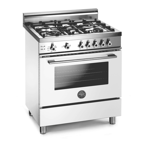
Installation, Service and User Instructions
DIMENSIONS: 30'' (762 mm)(W) x 253/16'' (640 mm)(D) x36'' (915 mm)(H)
Note: coloured parts employed on coloured models have same identical drawings and dimensions of the same
INOX parts already supplied for the basic INOX models; for this reason the ref. Frawing are the same and they
have not been supplied.
FREESTANDING GAS RANGES
BERTAZZONI
MODELS
X304GGVX
X304GGVBI
X304GGVCR
X304GGVGI
X304GGVRO
X304GGVVI
X304GGVVE
X304GGVBL
X304GGVNE
[M7S0GTU4X(2 or 5)A]
[M7S0GTU4W(2 or 5)A]
[M7S0GTU4D(2 or 5)A]
[M7S0GTU4I(2 or 5)A]
[M7S0GTU4R(2 or 5)A]
[M7S0GTU4L(2 or 5)A]
[M7S0GTU4V(2 or 5)A]
[M7S0GTU4U(2 or 5)A]
[M7S0GTU4N(2 or 5)A]
310356
Advertisement
Table of Contents

Related Manuals for Bertazzoni X304GGVX


Summary of Contents for Bertazzoni X304GGVX
- Page 1 Installation, Service and User Instructions FREESTANDING GAS RANGES BERTAZZONI DIMENSIONS: 30’’ (762 mm)(W) x 253/16’’ (640 mm)(D) x36’’ (915 mm)(H) MODELS X304GGVX [M7S0GTU4X(2 or 5)A] X304GGVBI [M7S0GTU4W(2 or 5)A] X304GGVCR [M7S0GTU4D(2 or 5)A] X304GGVGI [M7S0GTU4I(2 or 5)A] X304GGVRO [M7S0GTU4R(2 or 5)A]...
-
Page 2: What To Do If You Smell Gas
IMPORTANT - PLEASE READ AND FOLLOW -Before beginning installation, please read these instructions completely and carefully. -Do not remove permanently affixed labels, warnings, or plates from the product. This may void the warranty. -Please observe all local and national codes and ordinances. -Please ensure that this product is properly grounded. -
Page 3: Installation Instructions
Warning: do not place any pot or pan on the open oven door. The door is made of glass and it can break if loaded with a weight. Warning: this appliance must be used only with base feet properly installed. See installation instruction for details. -
Page 4: Height Adjustable Legs
INSTALLATION MANUAL ANTI-TIP STABILlTY DEVICE INSTALLATION INSTRUCTIONS 1. The anti-tip bracket have to be installed to the rear wall as shown. The height for the bracket location from the floor has to be determined after the range legs have been adjusted to the proper installation height - as shown in the installation instructions –... -
Page 5: Backguard Installation Instruction
BACKGUARD INSTALLATION INSTRUCTION It’s always compulsory to installa the riser even for an island installation Remove n°2 screws fixing worktop as shown in fig.1 Place front part of the backguard and attach it from bottom side with the two removed screws (point 2) as shown in fig .2 Fix the front part of the backguard with the screws supplied with the backguard kit (fig.3) Assemble back part with front part of the backguard and fix them with a screws supplied with the backguard kit... - Page 6 INSTALLATION SIDE-BY-SIDE TO KITCHEN CABINET 1. This range may be installed directly adjacent to existing 36" (91.5 cm) high cabinets. IMPORTANT: The top border of the worktop should be at the same level of the adjacent cabinet countertop. This can be accomplished by raising the unit using the adjustment spindles on the legs.
-
Page 7: Electrical Connection
COOKER HOOD INSTALLATION The bottom of the hood should be 25 " (65 cm) min. to 31 " (80 cm) above the countertop. This would typically result in the bottom of the hood being 61 " (156.2 cm) to 67 "... -
Page 8: Gas Connection
Wiring diagram For freestanding gas range model X304GGVX M7S0GTU4X(2 or 5)A CAUTION: label all wires prior to disconnection when servicing controls. Wiring errors can cause improper and dangerous operation. Verify proper operation after servicing. GAS CONNECTION All gas connections must be made according to national and local codes. The gas supply (service) line must be the same size or greater than the inlet line of the appliance. -
Page 9: Final Preparation
3. Flexible Connections: a) If the unit is to be installed with flexible couplings and/or quick disconnect fittings, the installer must use a heavy-duty, AGA design-certified commerciai flexible connector of at least 1/2" (1.3 cm) ID NPT (with suitable strain reliefs) in compliance with ANSI Z21.41 and Z21.69 standards. b) In Massachusetts: The unit must be installed with a 36"... -
Page 10: Replacement Parts
REPLACEMENT PARTS Only authorized replacement parts may be used in performing service on the appliance. Replacement parts are available from factory authorized parts distributors. Conversion to different types of gas Before carrying out any maintenance work, disconnect the appliance from the gas and electric supply. - Page 11 Fig. 9A Fig. 9B Fig. 10 Fig. 11 Follow the instructions below to change the broiler burner nozzle: 1) Loosen the screw and pull out the burner from the support being careful not to damage the ignition plug and the thermocouple (Fig.
-
Page 12: Adapting To Different Types Of Gas
Models X304GGVX [M7S0GTU4X (2 or 5)A] Adapting to different types of gas CAUTION: save the orifices removed from the appliance for future use Burner Position Injector Pressure Max Rate Min Rate By-pass diam. [mm.] Type [i.w.c.] [BTU/h] [BTU/h] diam. [mm] Auxiliary Rear L 0,90... -
Page 13: Service & Maintenance Instructions
SERVICE & MAINTENANCE INSTRUCTIONS Service and maintenance only to be carried out by an authorised person To replace parts such as burners, valves and electric components, the appliance must be open removing the worktop. Note: if the valves must be replaced, first disassemble the ignitions switches wires. It is recommended to replace the valve gaskets each time the valve is replaced, thus ensuring a perfect seal between the body and the gas train. -
Page 14: User Manual
USER MANUAL WARNINGS: Do not to cover the holes inside the oven with aluminium paper Do not to cover the burners of cooktop with aluminium paper Do not store any flammable objects or objects under pressure in the storage compartment Keeping appliance area clear and free from combustible materials, gasoline and other flammable vapors and liquid. -
Page 15: Control Panel Description
CONTROL PANEL DESCRIPTION On the control panel, small symbols show the function of each knob or key. Here as follows are the several controls that a cooker can have: the symbol shows the disposition of burners on the worktop, the full dot identifies the burner in object (in this case the front burner on the right). -
Page 16: Using The Gas Oven
WARNING: check the position of the burner caps before operation. Correct usage of pans: - Dry the bottom of the pan before placing it on the hotplate. - Use pots with a flat, thick bottom, except for wok cooking. - When using the burners, ensure that the handles of the pans are correctly positioned. Keep children away from the appliance. - Page 17 The ignition device should not be used for more than 15 seconds. If after that period the burner still has not been lit, do not use the device and open the door of the room or wait at least 60 seconds before trying to light the oven again.
- Page 18 To activate the convection fan use the selector placed on control panel. Turn the knob anti clockwise for activation of the convection fan +light Turn the knob clockwise to turn on the oven light. CONVECTION GAS OVEN COOKING TABLE TEMP °F/ °C HEIGHT MINUTES MEAT...
-
Page 19: Cleaning The Appliance
Please note here below details for after save service. Refer to warranty certificate for warranty condiftions Dealer /Importer: Name, address, phone SERVICE CENTERS Name Phone MANUFACTURER: BERTAZZONI SPA VIA PALAZZINA, 8 – 42016 – GUASTALLA (REGGIO E.) ITALY Tel. 0522/226411 – telefax 0522/226440 – http://www.bertazzoni-italia.com... -
Page 20: Spare Part List
SPARE PART LIST NUMBER COMPONENT DESCRIPTION 202387 BURNERS FLASK 202432 PART FOR DUAL WOK AND SEMI RAPID BURNERS 306003 THERMOSTAT CLIP 404213 WORKTOP FRONTGUARD 504160 COVER FOR SMALL FLAME SPREADER 504161 COVER FOR MEDIUM BURNER 504162 COVER FOR RAPID BURNER 504187 COVER IN FOR DUAL BURNER FLAME SPREADER 504186... - Page 21 502180 GAS VALVE BY PASS 047 RAPID 200327 STAINLESS STEEL SIDE 125003 SIDE BURGUNDY RED 125027 SIDE BLACK 125033 SIDE RED 125045 SIDE PURE WHITE 202389 RIGHT VERTICAL VENT 202214 FEET SUPPORT 201168 FIXING FOR WORK TABLE 308035 BUMPER FOR PAN SUPPORT 403343 HANDLE TERMINAL 408068...
Need help?
Do you have a question about the X304GGVX and is the answer not in the manual?
Questions and answers