Table of Contents
Advertisement
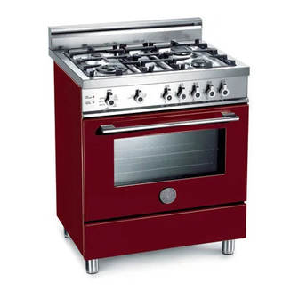
DIMENSIONS: 30'' (762 mm)(W) x 253/16'' (640 mm)(D) x36'' (915 mm)(H)
Models X304GGVX [M7S0GTU4X(2 or 5)A]
IMPORTANT - PLEASE READ AND FOLLOW
-Before beginning installation, please read these instructions completely and carefully.
-Do not remove permanently affixed labels, warnings, or plates from the product. This may void the warranty. -Please observe all local
and national codes and ordinances.
-Please ensure that this product is properly grounded.
-The installer should leave these instructions with the consumer who should retain for local inspector's use and for
future reference.
-The electrical plug should always be accessible.
Installation must conform with local codes or in the absence of codes, the National Fuel Gas Code ANSIZ223.1-latest edition. Electrical
installation must be in accordance with the National Electrical Code, ANIS/NFPA70
Installation must be in accordance with the current CAN/CGA-B149.1 National Gas Installation Code or CAN/CGA-B
Installation Code and/or local codes. Electrical installation must be in accordance with the current CSA C22.1 Canadian Electrical
Codes Part 1 and/or local codes.
Installation of any gas-fired equipment should be made by a licensed plumber. A manual gas shut-off valve must be installed in the gas
supply line ahead of the oven in the gas flow for safety and ease of service.
In Massachusetts:
All gas products must be installed by a "Massachusetts" licensed plumber or gasfitter. A "T" handle type manual
gas valve must be installed in the gas supply line to this appliance.
IMPORTANT: SAVE FOR LOCAL ELECTRICAL INSPECTOR'S USE.
READ AND SAVE THESE INSTRUCTIONS FOR FUTURE REFERENCE.
OBSERVE ALL GOVERNING CODES AND ORDINANCES.
WARNING: If the information in this manual is not followed exactly, a
fire or explosion may result causing property damage, personal injury
or death.
Do not store or use gasoline or other flammable vapors and liquids in
the vicinity of this or any other appliance.
WHAT TO DO IF YOU SMELL GAS
- Do not light any appliance.
- Do not touch any electrical switch.
- Do not use any phone in your building.
- Immediately call your gas supplier from a neighbor's phone. Follow
the gas supplier's instructions.
- If you cannot reach your gas suppliers, call the fire department.
Installation and service must be performed by a qualified installer,
service agency or the gas supplier.
310240
Installation, Service and User Instructions
FREESTANDING GAS RANGES
BERTAZZONI
Warning!
- This range can tip. Injury to persons could result.
- Install anti-tip device shipped with range.
-See Installation Instructions
-
latest edition and/or local codes. IN CANADA:
149.2,
Propane
Advertisement
Table of Contents

Subscribe to Our Youtube Channel
Related Manuals for Bertazzoni X304GGVVILP


Summary of Contents for Bertazzoni X304GGVVILP
- Page 1 Installation, Service and User Instructions FREESTANDING GAS RANGES BERTAZZONI DIMENSIONS: 30’’ (762 mm)(W) x 253/16’’ (640 mm)(D) x36’’ (915 mm)(H) Models X304GGVX [M7S0GTU4X(2 or 5)A] IMPORTANT - PLEASE READ AND FOLLOW -Before beginning installation, please read these instructions completely and carefully.
- Page 2 WARNING Read this instruction booklet before installing and using the appliance. The manufacturer will not be responsible for any damage to property or to persons caused by incorrect installation or improper use of the appliance. The manufacturer reserves the right to make changes to its products when considered necessary and useful, without affecting the essential safety and operating characteristics.
- Page 3 Requirements Room ventilation – Location and venting. ATTENTION: An exhaust fan may be used with the appliance; in each case it shall be installed in conformity with the appropriate national and local standards. ATTENTION: Exhaust hood operation may affect other vented appliances; in each case it shall be installed in conformity with the appropriate national and local standards.
- Page 4 BACKGUARD INSTALLATION INSTRUCTION Remove n°2 screws fixing worktop as shown in fig.1 Place front part of the backguard and attach it from bottom side with the two removed screws (point 2) as shown in fig .2 Fix the front part of the backguard with the screws supplied with the backguard kit (fig.3) Assemble back part with front part of the backguard and fix them with a screws supplied with the backguard kit (fig.4) WORKTOP FRONTGUARD INSTALLATION INSTRUCTIONS...
- Page 5 INSTALLATION SIDE-BY-SIDE TO KITCHEN CABINET 1. This range may be installed directly adjacent to existing 36" (91.5 cm) high cabinets. IMPORTANT: The top border of the worktop should be at the same level of the adjacent cabinet countertop. This can be accomplished by raising the unit using the adjustment spindles on the legs.
-
Page 6: Electrical Connection
COOKER HOOD INSTALLATION The bottom of the hood should be 25 " (65 cm) min. to 31 " (80 cm) above the countertop. This would typically result in the bottom of the hood being 61 " (156.2 cm) to 67 "... -
Page 7: Gas Connection
Wiring diagram For freestanding gas range model X304GGVX M7S0GTU4X(2 or 5)A CAUTION: label all wires prior to disconnection when servicing controls. Wiring errors can cause improper and dangerous operation. Verify proper operation after servicing. GAS CONNECTION All gas connections must be made according to national and local codes. The gas supply (service) line must be the same size or greater than the inlet line of the appliance. -
Page 8: Final Preparation
3. Flexible Connections: a) If the unit is to be installed with flexible couplings and/or quick disconnect fittings, the installer must use a heavy-duty, AGA design-certified commerciai flexible connector of at least 1/2" (1.3 cm) ID NPT (with suitable strain reliefs) in compliance with ANSI Z21.41 and Z21.69 standards. b) In Massachusetts: The unit must be installed with a 36"... -
Page 9: Replacement Parts
REPLACEMENT PARTS Only authorized replacement parts may be used in performing service on the appliance. Replacement parts are available from factory authorized parts distributors. Conversion to different types of gas Before carrying out any maintenance work, disconnect the appliance from the gas and electric supply. - Page 10 Fig. 9A Fig. 9B Fig. 10 Fig. 11 Follow the instructions below to change the broiler burner nozzle: 1) Loosen the screw and pull out the burner from the support being careful not to damage the ignition plug and the thermocouple (Fig.
- Page 11 Models X304GGVX [M7S0GTU4X (2 or 5)A] Adapting to different types of gas CAUTION: save the orifices removed from the appliance for future use Position Injector Pressure Max Rate Min Rate By-pass Burner diam. [mm.] Type [i.w.c.] [BTU/h] [BTU/h] diam. [mm] 0,90 4"...
-
Page 12: Service & Maintenance Instructions
WARNING: The above-mentioned adjustment should be made only for natural gas, while for operation with liquid gas the screw must be locked at the end in a clockwise direction. The broiler burner always operates at maximum and therefore no minimum adjustment is required. SERVICE &... -
Page 13: Control Panel Description
CONTROL PANEL DESCRIPTION On the control panel, small symbols show the function of each knob or key. Here as follows are the several controls that a cooker can have: the symbol shows the disposition of burners on the worktop, the full dot identifies the burner in object (in this case the front burner on the right). -
Page 14: Using The Gas Oven
Tips for using burners correctly: WARNING: During use of each gas burner(s) adjust the burner flame size properly so it does not extend beyond the edge of the cooking utensil. This is an instruction based on safety considerations - Use suitable pots for each burner (see Fig. and Table ) - When the liquid is boiling, turn down the knob to the MINIMUM position. - Page 15 The oven burner can be ignited in different ways: - Manual lighting (it is always possible even when the power is cut off): To light the oven, open the oven door and turn the knob at maximum position . At the same time put a lit match next to the ignition tube that is visible on the oven level .
- Page 16 TEA CAKE 375/190 50-55 BRIOCHES 345/175 25-30 SPONGE CAKE 450/235 RING CAKE 375/190 30-40 SWEET PUFF PASTRIES 430/220 RAISIN LOAF 430/220 15-20 STRUDEL 355/180 15-20 SAVOIA COOKIES 375/190 APPLE FRITTERS 430/220 SAZOIARDI SANDWICH 430/220 20-30 TOAST SANDWICH 480/250 BREAD 430/220 PIZZA 430/220 To activate the convection fan use the selector placed on control panel.
-
Page 17: Cleaning The Appliance
- Manual lighting: Just completely open the oven door, turn the knob so that the relative symbol matches the indicator, while pressing the knob, and, at the same time, put a lit match next to the burner. Make sure that the burner is completely lit and after about 10 seconds release the knob. -
Page 18: After-Sale Service
Please note here below details for after save service. Refer to warranty certificate for warranty condiftions Dealer /Importer: Name, address, phone SERVICE CENTERS Name Phone MANUFACTURER: BERTAZZONI SPA VIA PALAZZINA, 8 – 42016 – GUASTALLA (REGGIO E.) ITALY Tel. 0522/226411 – telefax 0522/226440 – http://www.bertazzoni-italia.com... -
Page 19: Spare Part List
SPARE PART LIST SPARE PARTS LIST COMPONENT DESCRIPTION M7S0GTU4X5AUA X304GGVX - GAS COOKER 601736 CIRCUIT DIAGRAM 310240 USER MANUAL 202387 BURNERS FLASK 202432 PART FOR DUAL WOK AND SEMI RAPID BURNERS 510507 SMALL BURNER 510508 SEMI RAPID BURNER 510509 RAPID BURNER 510511 DUAL BURNER 504128... - Page 20 505013 SUPPORT FOR GRILL BURNER NOZZLE 508021 TERMOCOUPLE MM600 508025 TERMOCOUPLE MM300 508034 TERMOCOUPLE ULTRA-RAPID BURNER 603020 OVEN CONVECTION FAN 603019 COOLING FAN 602039 COMMUTATOR 608046 OVEN BULB WITH HOLDER 601991 TERMINAL SEPARATOR 608047 SMALL WARNING LIGHT 503121 THERMOSTAT 408058 ADAPTER FOR WOK BURNER PAN SUPPORT 604070 DASYCHAIN SWITCH...
- Page 21 1803 501756 TUBE FOR EXTERNAL DUAL BURNER 1804 501757 TUBE FOR INTERNAL DUAL BURNER 4106 405047 HINGE FOR FLAP DOOR 4301 200328 RIGHT SIDE PROFILE 4302 200329 LEFT SIDE PROFILE 5140 504776 GRILL BURNER...
Need help?
Do you have a question about the X304GGVVILP and is the answer not in the manual?
Questions and answers