Table of Contents
Advertisement
Advertisement
Table of Contents

Related Manuals for Bertazzoni H366GGV


Summary of Contents for Bertazzoni H366GGV
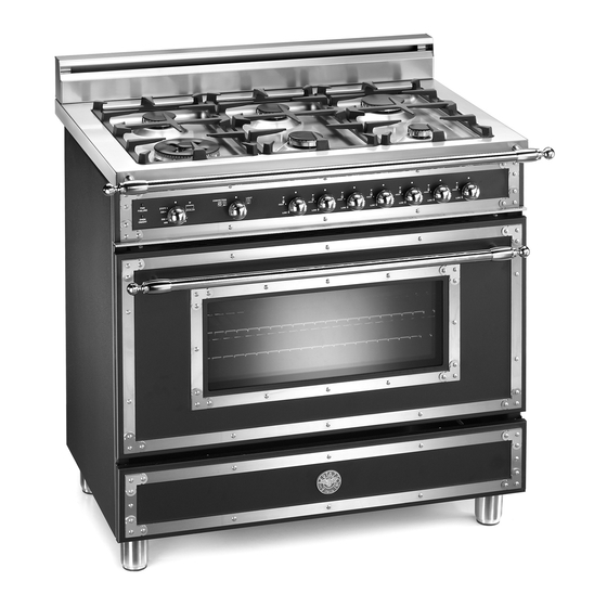
- Page 1 Installation, Service and User Instructions FREESTANDING GAS RANGES BERTAZZONI DIMENSIONS: 36’’ (911 mm)(W) x 25 ’’ (640 mm)(D) x36’’ (911 mm)(H) MODELS H366GGVCR [M3Y0GTV4D(2 or 5)A] H366GGVNE [M3Y0GTV4N(2 or 5)A] H366GGVVI [M3Y0GTV4L(2 or 5)A] 310291...
-
Page 2: Important - Please Read And Follow
Installation of any gas-fired equipment should be made by a licensed plumber. A manual gas shut-off valve must be installed in the gas supply line ahead of the oven in the gas flow for safety and ease of service. Warning! - This range can tip. -
Page 3: Installation Instructions
This appliance has been designed for non-professional, domestic use only. Warning: do not use this appliance to heat a room. Warning: do not place any pot or pan on the open oven door. The door is made of glass and it can break if loaded with a weight. - Page 4 ATTENTION: A manual valve shall be installed in an accessible location in the gas line external to the appliance for the purpose of turning on or shutting off gas to the appliance WARNING: Do not use aerosol sprays in the vicinity of this appliance while it is in operation Requirements Room ventilation –...
- Page 5 ANTI-TIP STABILlTY DEVICE INSTALLATION INSTRUCTIONS 1. The anti-tip bracket have to be installed to the rear wall as shown. The height for the bracket location from the floor has to be determined after the range legs have been adjusted to the proper installation height - as shown in the installation instructions –...
-
Page 6: Backguard Installation Instruction
It’s always compulsory to installa the riser even for an island installation Remove n°2 screws fixing worktop as shown in fig.1 Place front part of the backguard and attach it from bottom side with the two removed screws (point 2) as shown in fig .2 Fix the front part of the backguard with the screws supplied with the backguard kit (fig.3) - Page 7 WORKTOP FRONT HANDLE INSTALLATION INSTRUCTIONS In order to increase the clearance between front edge of the worktop and the burners for your safety it is recomended to install the worktop front handle supplied with the appliance. For installation instructions follow...
- Page 8 36" (91.4 cm) high. There minimum of 6" (15.2 cm) side clearance. 3. Within the side clearance to combustible vertical surfaces above 36" (91.5 cm) , the maximum wall cabinet depth must cm) above countertop level and be 13" (33.0 cm) and wall cabinets within this side clearance must be 18" (45.7 countertop hightness shall be from 37”...
-
Page 9: Electrical Connection
Cooling fan failure. In case of a cooling fan failure the frontal red indicator "Fan Failure" will light up. If this happens, please turn off the appliance immediately, call the nearest after sale assistance service center and do not use the appliance until the cooling fan system of the appliance has been properly repaired by a qualified technician. - Page 10 Wiring diagram For freestanding gas range model H366GGV M3Y0GTV4(L,N,D)(2 or 5)A CAUTION: label all wires prior to disconnection when servicing controls. Wiring errors can cause improper and dangerous operation. Verify proper operation after servicing. For freestanding gas range model H365GGV M3W0GTV4X(L,N,D)(2 or 5)A CAUTION: label all wires prior to disconnection when servicing controls.
-
Page 11: Gas Connection
All gas connections must be made according to national and local codes. The gas supply (service) line must be the same size or greater than the inlet line of the appliance. This range uses a 1/2" NPT inlet (see fig. in this chapter for details of gas connections installations).On all pipe joints use sealant resistant to LP gas. -
Page 12: Final Preparation
The pressure regulator supplied with the appliance is a convertible type pressure regulator for use with Natural Gas at a nominal outlet pressure of 4” w.c. or LP gas at a nominal outlet pressure of 11” w.c. and it is pre-arranged from the factory to operate with one of these gas/pressure as indicated in the labels affixed on the appliance, package and Instruction booklet. - Page 13 1) Loosen the screw and pull out the burner from the support being careful not to damage the ignition plug and the thermocouple (Fig. 12). 2) Unscrew the nozzle C (Fig. 12) using a 7 mm spanner and replace it with the nozzle needed for the new type of gas according to what is indicated in TABLE shown below.
-
Page 14: Adapting To Different Types Of Gas
Oven burner adjustment: follow the instructions below to adjust the primary air for the over burner: 1) Remove the oven bottom. 2) Loosen the screw P and adjust the position X of the Venturi cone (Fig. 13) according to the measurements indicated in table 4. -
Page 15: Service & Maintenance Instructions
2) Remove the knob of the valve that is press fit on the rod of that valve. 3) The cooker is equipped with safety valves, use a small slotted screwdriver the choke valve located on the valve body and turn the choke screw to the right or left until the burner flame is adjusted to minimum 4) Make sure that the flame does not go out when switching quickly from the MAXIMUM to the MINIMUM position. -
Page 16: User Manual
Keeping appliance area clear and free from combustible materials, gasoline and other flammable vapors and liquid. Do not store dangerous or flammable material in the cabinet areas above appliance; store them in a safe place in order to avoid potential hazards. -
Page 17: Control Panel Description
CONTROL PANEL DESCRIPTION On the control panel, small symbols show the function of each knob or key. Here as follows are the several controls that a cooker can have: the symbol shows the disposition of burners on the worktop, the full dot identifies the burner in object (in this case the front burner on the right). -
Page 18: Using The Gas Oven
- When cooking foods with oil and fat, which are very flammable, the user should not leave the appliance unattended. WOK PAN: To use the wok pan, please utilize a suitable wok adaptor grid; wok pan external diameter shall not be less than 10”... - Page 19 - Manual lighting (it is always possible even when the power is cut off): To light the oven, open the oven door and turn the knob at maximum position . At the same time put a lit match next to the ignition tube that is visible on the oven level .
- Page 20 To activate the convection fan use the selector placed on control panel. Turn the knob anti clockwise for activation of the convection fan +light Turn the knob clockwise to turn on the oven light. CONVECTION GAS OVEN COOKING TABLE TEMP °F/ °C...
- Page 21 - Manual lighting: Just completely open the oven door, turn the knob so that the relative symbol matches the indicator, while pressing the knob, and, at the same time, put a lit match next to the burner. Make sure that the burner is completely lit and after about 10 seconds release the knob.
-
Page 22: Cleaning The Appliance
- Remove any splliage from the painted parts as soon as possible - Do not permit to citrus or tomato juice to remain on stainless steel or colored surface for a long time, as citric acid can permanently discolor the surfaces. -
Page 23: Spare Parts List
SPARE PARTS LIST NUMBER COMPONENT DESCRIPTION QUANTITY 202387 BURNERS FLASK 202432 PART FOR DUAL WOK AND SEMI RAPID BURNERS 306003 THERMOSTAT CLIP 504160 COVER FOR SMALL FLAME SPREADER 504161 COVER FOR MEDIUM BURNER 504162 COVER FOR RAPID BURNER 504187 COVER IN FOR DUAL BURNER FLAME SPREADER... - Page 24 RIGHT SIDE PROFILE BLACK 4301 108677 RIGHT SIDE PROFILE BEIGE 4301 108678 RIGHT SIDE PROFILE BORDEAUX 4302 108661 LEFT SIDE PROFILE BLACK 4302 108674 LEFT SIDE PROFILE BEIGE 4302 108675 LEFT SIDE PROFILE BORDEAUX 5140 504185 GRILL BURNER + SPARK PLUG + THERMOC.
Need help?
Do you have a question about the H366GGV and is the answer not in the manual?
Questions and answers