
Subscribe to Our Youtube Channel
Related Manuals for Bertazzoni X244GGVX


Summary of Contents for Bertazzoni X244GGVX
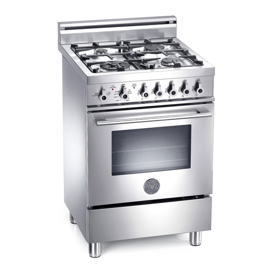
- Page 1 Installation, Service and User Instructions FREESTANDING GAS RANGES BERTAZZONI DIMENSIONS: 24’’ (605 mm)(W) x 25 ’’ (640 mm)(D) x36’’ (911 mm)(H) MODEL X244GGVX [MLS0GTU4X(2 or 5)A] 310287...
-
Page 2: Important - Please Read And Follow
IMPORTANT - PLEASE READ AND FOLLOW -Before beginning installation, please read these instructions completely and carefully. -Do not remove permanently affixed labels, warnings, or plates from the product. This may void the warranty. -Please observe all local and national codes and ordinances. -Please ensure that this product is properly grounded. -
Page 3: Installation Instructions
WARNING Read this instruction booklet before installing and using the appliance. The manufacturer will not be responsible for any damage to property or to persons caused by incorrect installation or improper use of the appliance. The manufacturer reserves the right to make changes to its products when considered necessary and useful, without affecting the essential safety and operating characteristics. - Page 4 ATTENTION: A manual valve shall be installed in an accessible location in the gas line external to the appliance for the purpose of turning on or shutting off gas to the appliance WARNING: Do not use aerosol sprays in the vicinity of this appliance while it is in operation Requirements Room ventilation –...
-
Page 5: Backguard Installation Instruction
Height adjustable legs: 1. Legs are packed in the top box. 2. Legs should be installed with the appliance being near the location of final installation, they are not secure for long transport. After unpacking the range, raise it about a foot to insert the legs in their bases assembled on the lower part of the cooker and lower the range gently to keep any undue strain from legs and mounting hardware. - Page 6 WORKTOP FRONTGUARD INSTALLATION INSTRUCTIONS In order to increase the clearance between front edge of the worktop and the burners for your safety it is recomended to install the worktop frontguard supplied with the appliance. For installation instructions follow the instructions indicated in the following figures...
- Page 7 INSTALLATION SIDE-BY-SIDE TO KITCHEN CABINET 1. This range may be installed directly adjacent to existing 36" (91.5 cm) high cabinets. IMPORTANT: The top border of the worktop should be at the same level of the adjacent cabinet countertop. This can be accomplished by raising the unit using the adjustment spindles on the legs.
-
Page 8: Electrical Connection
COOKER HOOD INSTALLATION The bottom of the hood should be 25 " (65 cm) min. to 31 " (80 cm) above the countertop. This would typically result in the bottom of the hood being 61 " (156.2 cm) to 67 "... -
Page 9: Gas Connection
Wiring diagram For freestanding gas range model X244GGV MLS0GTU4X(2 or 5)A CAUTION: label all wires prior to disconnection when servicing controls. Wiring errors can cause improper and dangerous operation. Verify proper operation after servicing. GAS CONNECTION All gas connections must be made according to national and local codes. The gas supply (service) line must be the same size or greater than the inlet line of the appliance. -
Page 10: Final Preparation
3. Flexible Connections: a) If the unit is to be installed with flexible couplings and/or quick disconnect fittings, the installer must use a heavy-duty, AGA design-certified commerciai flexible connector of at least 1/2" (1.3 cm) ID NPT (with suitable strain reliefs) in compliance with ANSI Z21.41 and Z21.69 standards. b) In Canada: CAN 1-6.10-88 metal connectors for gas appliances and CAN 1-6.9 M79 quick disconnect device for use with gas fuel. -
Page 11: Replacement Parts
REPLACEMENT PARTS Only authorized replacement parts may be used in performing service on the appliance. Replacement parts are available from factory authorized parts distributors. Conversion to different types of gas Before carrying out any maintenance work, disconnect the appliance from the gas and electric supply. -
Page 12: Adapting To Different Types Of Gas
2) Unscrew the nozzle R (Fig. 11) using a 7 mm spanner and replace it with the nozzle needed for the new type of gas according to what is indicated in Table below. Models X244GGVX [MLS0GTU4X(2 or 5)A] Adapting to different types of gas... -
Page 13: Service & Maintenance Instructions
REGULATION OF BURNERS Work surface burner adjustment: follow the instructions below to adjust the work surface burner minimum: 1) Light the burner and set the knob to the MINIMUM position (small flame). 2) Remove the knob of the valve that is press fit on the rod of that valve. 3) The cooker is equipped with safety valves, use a small slotted screwdriver the choke valve located on the valve body and turn the choke screw to the right or left until the burner flame is adjusted to minimum 4) Make sure that the flame does not go out when switching quickly from the MAXIMUM to the MINIMUM position. -
Page 14: User Manual
USER MANUAL WARNINGS: Do not to cover the holes inside the oven with aluminium paper Do not to cover the burners of cooktop with aluminium paper Do not store any flammable objects or objects under pressure in the storage compartment Keeping appliance area clear and free from combustible materials, gasoline and other flammable vapors and liquid. -
Page 15: Control Panel Description
CONTROL PANEL DESCRIPTION On the control panel, small symbols show the function of each knob or key. Here as follows are the several controls that a cooker can have: the symbol shows the disposition of burners on the worktop, the full dot identifies the burner in object (in this case the front burner on the right). -
Page 16: Using The Gas Oven
WARNING: check the position of the burner caps before operation. Correct usage of pans: - Dry the bottom of the pan before placing it on the hotplate. - Use pots with a flat, thick bottom, except for wok cooking. - When using the burners, ensure that the handles of the pans are correctly positioned. Keep children away from the appliance. - Page 17 The oven burner can be ignited in different ways: - Manual lighting (it is always possible even when the power is cut off): To light the oven, open the oven door and turn the knob at maximum position . At the same time put a lit match next to the ignition tube that is visible on the oven level .
- Page 18 To activate the convection fan use the selector placed on control panel. Turn the knob anti clockwise for activation of the convection fan +light Turn the knob clockwise to turn on the oven light. CONVECTION GAS OVEN COOKING TABLE TEMP °F/ °C HEIGHT MINUTES MEAT...
-
Page 19: Cleaning The Appliance
Please note here below details for after save service. Refer to warranty certificate for warranty condiftions Dealer /Importer: Name, address, phone SERVICE CENTERS Name Phone MANUFACTURER: BERTAZZONI SPA VIA PALAZZINA, 8 – 42016 – GUASTALLA (REGGIO E.) ITALY Tel. +39 0522/226411 – telefax +39 0522/226440 – http://www.bertazzoni-italia.com... -
Page 20: Spare Parts List
SPARE PARTS LIST NUMBER COMPONENT DESCRIPTION QUANTITY X24 4 GGV X - GAS COOKER 202387 BURNERS FLASK 202432 PART FOR DUAL WOK AND SEMI RAPID BURNERS 306003 THERMOSTAT CLIP 404229 WORKTOP FRONTGUARD 504160 COVER FOR SMALL FLAME SPREADER 504161 COVER FOR MEDIUM BURNER 504162 COVER FOR RAPID BURNER 504187... - Page 21 202490 WARMER DROWER UPPERSIDE PROTECTION PANEL 502148 GAS VALVE BY PASS 036 SEMI-RAPID 502150 GAS VALVE BY PASS 065 DUAL OUTER 502179 GAS VALVE BY PASS 029 SMALL/DUAL INNER 502180 GAS VALVE BY PASS 047 RAPID 200327 STAINLESS STEEL SIDE 202493 RIGHT VERTICAL VENT 202214...
- Page 29 Installation, Service and User Instructions (instruction en francais page 12) BERTAZZONI Built-in gas hotplates DIMENSIONS: 23 ’’ (W) x 19 ’’ (590 mm) (500 mm) Models P24 4 00 X [P680..T4X5D] IMPORTANT: SAVE FOR LOCAL ELECTRICAL INSPECTOR’S USE. READ AND SAVE THESE INSTRUCTIONS FOR FUTURE REFERENCE.
- Page 30 INDEX: Installation manual……………………………………..……………………………..pag.2 Inserting the hotplate……………………………………………..…………………..pag.3 Requirements……………………………………..……………………………….…..pag.3-4 Attaching the hotplate……………………………………..………………………….pag.4 Gas connection……………………………………..…………………………………pag.4-5-6 Electrical connection……………………………………..……………………….…..pag.6 Wiring diagrams……………………………………..…………………………….…..pag.6 Instructions for assembly of load bearing bottom protection.…………………….pag.6-7 Room ventilation…………………………………….…………………………………pag.7 Location and venting…………………………………….…………………………….pag.7 Replacement of nozzles……………………………………..………………………..pag.7 Regulation of burners……………………………………………...………………….pag.8 Service & maintenance instructions……………………………..…………………..pag.8 User instructions……………………………………………..……………………….. pag.9 Descriptions…………………………………………………………………………….pag.9 Using burners……………………………………………………..……………………pag.9-10 Cleaning the appliance……………………………………………..…………………pag.10...
-
Page 31: Inserting The Hotplate
Inserting the hotplate After having removed the various loose parts from the internal and external packing, make sure that the hotplate in not damaged and is suitable for the specific gas usage. The gas type label is on the underside of the hotplate base. -
Page 32: Attaching The Hotplate
2. Side clearances (Minimum values) The different side clearances shall be in accordance with the minimum values indicated in the table n.1 and are shown and in the fig. 1 The cooking surface area is defined as that part of the appliance where cooking normally takes place and does not include those parts of the appliance containing control knobs. - Page 33 4. For LPG models the gas supply is connected to the regulator which is supplied loose. The inlet connection has a 1/2” B.S.P. male thread. IT IS ESSENTIAL THAT THE ELBOW ON THE APPLIANCE BE HELD FIRMLY WITH A SPANNER WHEN CONNECTING THE SUPPLY. DO NOT OVER TIGHTEN. The regulated pressure For LPG is 11”...
-
Page 34: Wiring Diagrams
9. Sometimes the burners will not ignite immediately and seem to ‘blow’ slightly when they do ignite. This usually due to air in the gas lines, which will clear itself within seconds. 10. If after following the instructions given, satisfactory performance cannot be obtained, contact the local gas authority for advice and assistance. - Page 35 SECTION VIEW OF THE RIGHT ASSEMBLY Room ventilation – Location and venting. ATTENTION: An exhaust fan may be used with the appliance; in each case it shall be installed in conformity with the national standards in force. ATTENTION: Exhaust hood operation may affect other vented appliances; in each case it shall be installed in conformity with the national standards in force.
- Page 36 Regulation of burners Regulation of the "MINIMUM" on the burners To regulate the minimum on the burners carry out the following procedure indicated below: 1) Turn on the burner and put the knob onto position MINIMUM ( small flame ). 2) Remove the knob ( Fig.
-
Page 37: User Instructions
User instructions WARNINGS: Keeping appliance area clear and free from combustible materials, gasoline and other flammable vapors and liquid. Do not store dangerous or flammable material in the cabinet areas above appliance; store them in a safe place in order to avoid potential hazards. For safe use of appliance, do not use it for space heating. - Page 38 Fig.16 Table B Burner Recommended pan diameters inches (mm) Small ”-55 ”(90 – 140) ½ Medium ”- 102 ”(140 – 260) Double ring (wok) ”-102 ” (220 – 260) Correct usage of pans: - Dry the bottom of the pan before placing it on the hotplate. - Use pots with a flat, thick bottom, except for wok cooking.
-
Page 39: After-Sale Service
Please note here below details for after save service. Refer to warranty certificate for warranty condiftions Dealer /Importer: Name, address, phone SERVICE CENTERS Name Phone MANUFACTURER: BERTAZZONI SPA VIA PALAZZINA, 8 – 42016 – GUASTALLA (REGGIO E.) ITALY Tel. 0522/226411 – telefax 0522/226440 – http://www.bertazzoni-italia.com... - Page 40 Installation, Service et Instructions pour l’Utilisateur BERTAZZONI Tables de cuisson gaz à encastrer DIMENSIONS: 23 ’’ (W) x 19 ’’ (590 mm) (500 mm) Modèles P24 4 00 X [P680..T4X5D] IMPORTANT: A CONSERVER POUR L’UTILISATION DE L’INSPECTEUR ELECTRIQUE LOCAL. LIRE ET CONSERVER CES INSTRUCTIONS POUR LES REFERENCES FUTURES.
- Page 41 INDEX: Manuel pour l’installation..…………………………………..………………………...page 13-14 Insertion de la table de cuisson..………………………………..………………….. .page 14 Exigences…..……………………………………..……………………………….….. page 14 Fixation de la table de cuisson….………………………..………………………….. page 15 Branchement du gaz………………………………..………………………………….page 16 Branchement électrique…………………………………..……………………….…..page 17 Schéma de câblage..………………………………..…………………………….…...page 17 Instructions de montage de la protection du fond portant …..…………….………page 18 Ventilation du local………………………………………………………………...
- Page 42 La pression d’alimentation maximum du gaz en entrée dans le régulateur de pression de l’appareil à gaz est de 20’’ colonne d’eau (w.c.) (5 kPa) La pression d’alimentation minimum du gaz pour le contrôle du réglage du régulateur doit être au moins de 1“...
-
Page 43: Fixation De La Table De Cuisson
Exigences 1. Distances des meubles suspendus (Valeurs minimum) Les distances minimum devront être conformes aux valeurs minimum indiquées dans la table n.1 et sont illustrées dans la fig. 1- 2 Les hottes de cuisine et les ventilateurs aspirant doivent être installés selon les instructions du fabricant. Cependant, dans aucun cas, la distance entre la partie supérieure du brûleur le plus haut de l’appareil de cuisson et la hotte d’aspiration devra être inférieure au 30”( 762mm). -
Page 44: Branchement Du Gaz
Branchement du gaz Avant de brancher l’appareil à l’alimentation gaz, enlevez d’abord le bouchon en plastique qui est monté en force dans le raccord d’admission du gaz; pour l’enlever, le tirer simplement. 1. Vérifiez l’étiquette du ‘’type de gaz’’ attachée à la table de cuisson. Les détails concernant les dimensions des injecteurs utilisés sont indiqués sur la plaquette des données située sur la base de l’appareil. -
Page 45: Branchement Électrique
7. Pour vérifier l'itroduction de pression dans l'appareil il faut agir comme il suit: a) Disjoindre la courent électrique avant de vérifier la pression. b) Enlever un des chapeaux de brûleurs et la relative tete bruleur au fin d'accéder au injector du brûleur. c) Mettre en position le détecteur de pression directement sur l'injector du brûleur ensuite ouvrir la relative manette en la gardant poussée à... - Page 46 Instructions de montage de la protection du fond portant 1 VIS M5 2 PROTECTION DU FOND PORTANT 3 RIVET M5 4 FOND PORTANT 5 PLAN DE TRAVAIL Après avoir enstallé la table cuisson (5) proceder avec le montage de la protection du fond portant (2) en le plaçant comme indiqué...
- Page 47 - REMPLACEMENT DES BECS POUR L’UTILISATION AVEC D’AUTRES TYPES DE GAZ: Pour changer les becs des brûleurs, suivez le procédé suivant: Soulevez les brûleurs et dévissez les becs ( Fig. 6) en employant une clé réglable de 7 mm et changez les becs avec ceux conçus pour la nouvelle alimentation de gaz, selon les informations fournies dans le TABLEAU A ci-dessous.
-
Page 48: Instructions Pour L'utilisateur
1) Dévisser à la main le bouchon en plastique supérieur du régulateur (Fig. 5A). 2) Dévisser à la main la pièce en plastique blanche vissée sous le bouchon en métal susmentionné, ensuite le visser encore dans le sens opposé sous le bouchon en métal (pour la référence du gaz voir l’écriture “LP” et “NAT”... -
Page 49: Utilisation Des Brûleurs
Descriptions LEGENDE DESCRIPTIVE POUR LES TABLES DE CUISSON 1. Brûleur petit 2. Brûleur moyen 3. Brûleur double couronne (poêle chinoise) 4. Bouton de commande du brûleur frontal à gauche 5. Bouton de commande du brûleur arrière à gauche 6. Bouton de commande du brûleur arrière à droite 7. -
Page 50: Centres De Service
Se référer au certificat de garantie pour les conditions de la garantie. Revendeur /Importateur: Nom, adresse, téléphone CENTRES DE SERVICE Téléphone FABRICANT: BERTAZZONI SPA VIA PALAZZINA, 8 – 42016 – GUASTALLA (REGGIO E.) ITALY Tél. +39 0522/226411 – fax +39 0522/226440 – http://www.bertazzoni-italia.com... - Page 51 SPARE PARTS LIST NUMBER DESCRIPTION COMPOSANT P24400X - BUILT-IN HOB 202366 LOAD BEARING BOTTOM FOND PORTEFAIX 202358 DOUBLE CARTER P6 PROTECTION DU FOND PORTANT 202271 FIXING HOOK CROCHET DE FIXAGE 504160 COVER FOR SMALL FLAME SPREADER COUVERCLE PETIT AVD 504161 COVER FOR MEDIUM BURNER COUVERCLE MOYEN ARD ARG 504158...
Need help?
Do you have a question about the X244GGVX and is the answer not in the manual?
Questions and answers