Table of Contents
Advertisement
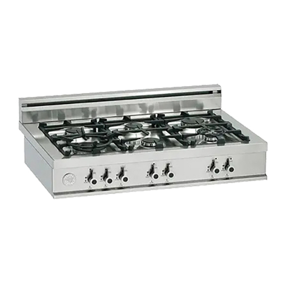
Models C36500X (Z36500X)
Models C36600X (Z36600X)
IMPORTANT - PLEASE READ AND FOLLOW
-Before beginning installation, please read these instructions completely and carefully.
-Do not remove permanently affixed labels, warnings, or plates from the product. This may void the warranty. -Please observe all local
and national codes and ordinances.
-Please ensure that this product is properly grounded.
-The installer should leave these instructions with the consumer who should retain for local inspector's use and for
future reference.
-The electrical plug should always be accessible.
Installation must conform with local codes or in the absence of codes, the National Fuel Gas Code ANSIZ223.1-latest edition. Electrical
installation must be in accordance with the National Electrical Code, ANIS/NFPA70
Installation must be in accordance with the current CAN/CGA-B149.1 National Gas Installation Code or CAN/CGA-B
Installation Code and/or local codes. Electrical installation must be in accordance with the current CSA C22.1 Canadian Electrical
Codes Part 1 and/or local codes.
Installation of any gas-fired equipment should be made by a licensed plumber. A manual gas shut-off valve must be installed in the gas
supply line ahead of the oven in the gas flow for safety and ease of service.
In Massachusetts:
All gas products must be installed by a "Massachusetts" licensed plumber or gasfitter. A "T" handle type manual
gas valve must be installed in the gas supply line to this appliance.
IMPORTANT: SAVE FOR LOCAL ELECTRICAL INSPECTOR'S USE.
READ AND SAVE THESE INSTRUCTIONS FOR FUTURE REFERENCE.
OBSERVE ALL GOVERNING CODES AND ORDINANCES.
WARNING: If the information in this manual is not followed exactly, a
fire or explosion may result causing property damage, personal injury
or death.
Do not store or use gasoline or other flammable vapors and liquids in
the vicinity of this or any other appliance.
WHAT TO DO IF YOU SMELL GAS
- Do not light any appliance.
- Do not touch any electrical switch.
- Do not use any phone in your building.
- Immediately call your gas supplier from a neighbor's phone. Follow
the gas supplier's instructions.
- If you cannot reach your gas suppliers, call the fire department.
Installation and service must be performed by a qualified installer,
service agency or the gas supplier.
310200
Installation, Service and User Instructions
Built-in gas cooktops
BERTAZZONI
DIMENSIONS: 36'' (915 mm)(W) x 253/16'' (640 mm)(D)
[C3W0..U4X(2 or 5)A]
[C3Y0..U4X(2 or 5)A]
-
latest edition and/or local codes. IN CANADA:
149.2,
Propane
Advertisement
Table of Contents

Related Manuals for Bertazzoni C36500X


Summary of Contents for Bertazzoni C36500X
-
Page 1: What To Do If You Smell Gas
Installation, Service and User Instructions Built-in gas cooktops BERTAZZONI DIMENSIONS: 36’’ (915 mm)(W) x 253/16’’ (640 mm)(D) Models C36500X (Z36500X) [C3W0..U4X(2 or 5)A] Models C36600X (Z36600X) [C3Y0..U4X(2 or 5)A] IMPORTANT - PLEASE READ AND FOLLOW -Before beginning installation, please read these instructions completely and carefully. - Page 2 WARNING Read this instruction booklet before installing and using the appliance. The manufacturer will not be responsible for any damage to property or to persons caused by incorrect installation or improper use of the appliance. The manufacturer reserves the right to make changes to its products when considered necessary and useful, without affecting the essential safety and operating characteristics.
-
Page 3: Backguard Installation Instruction
INSTALLATION MANUAL BACKGUARD INSTALLATION INSTRUCTION Please follow the following installation instructions afther installing the cooktop: Remove n°2 screws fixing worktop as shown in fig.1 Place front part of the backguard and attach it from bottom side with the two removed screws (point 2) as shown in fig .2 Fix the front part of the backguard with the screws supplied with the backguard kit (fig.3) Assemble back part with front part of backguard and fix them with a screw supplied with the backguard kit... - Page 4 PROXIMITY TO SIDE CABINET INSTALLATION This rangetop may be installed directly adjacent to existing 36" (91.5 cm) high base cabinets. IMPORTANT: The top grate support MUST be 3/8" (.95 cm) above the adjacent base cabinet countertOP. The rangetop CANNOT be installed directly adjacent to sidewalls, tall cabinets, tall appliances, or other side vertical surfaces above 36"...
-
Page 5: Electrical Connection
COOKER HOOD INSTALLATION The bottom of the hood should be 25 ½ " (65 cm) min. to 31 ½ " (80 cm) above the countertop. Refer to the rangehood installation instructions for additional information. These dimensions provide for safe and efficient operation of the hood. ELECTRICAL CONNECTION This unit is manufactured for a polarized, grounded 120 volt/60 Hz, 16 amp system. - Page 6 Wiring diagram For freestanding gas range model C36600X (Z36 6 00 X) C3Y0..U4X(2 or 5)A CAUTION: label all wires prior to disconnection when servicing controls. Wiring errors can cause improper and dangerous operation. Verify proper operation after servicing. For freestanding gas range model C36500X (Z36 5 00 X) C3W0..U4X(2 or 5)A CAUTION: label all wires prior to disconnection when servicing controls.
-
Page 7: Gas Connection
GAS CONNECTION All gas connections must be made according to national and local codes. This gas supply (service) line must be the same size or greater than the inlet line of the appliance. This range uses a 1/2" NPT (see fig. in this chapter for details of gas connections installations) inlet. -
Page 8: Replacement Parts
REPLACEMENT PARTS Only authorized replacement parts may be used in performing service on the appliance. Replacement parts are available from factory authorized parts distributors. CONVERSIONE TO DIFFERENT TYPES OF GAS Before carrying out any maintenance work, disconnect the appliance from the gas and electric supply. -
Page 9: Adapting To Different Types Of Gas
Models C36600X (Z36 6 00 X) [C3Y0..U4X(2 or 5)A] Adapting to different types of gas Burner Position Injector Pressure Max Rate Min Rate By-pass diam. [mm.] Type [i.w.c.] [BTU/h] [BTU/h] diam. [mm] Auxiliary Front R 0,90 4” 3400 Regulated 0,54 LP (Propane) 11”... -
Page 10: Service & Maintenance Instructions
SERVICE & MAINTENANCE INSTRUCTIONS Service and maintenance only to be carried out by an authorised person To replace parts such as burners, valves and electric components, the appliance must be open removing the worktop. Note: if the valves must be replaced, first disassemble the ignitions switches wires. It is recommended to replace the valve gaskets each time the valve is replaced, thus ensuring a perfect seal between the body and the gas train. -
Page 11: Using Burners
USING BURNERS A diagram is etched on the control panel above each knob which indicates which burner corresponds to that knob. Manual ignition: Manual ignition is always possible even when the power is cut off or in the event of prolonged power failure. Turn the knob that corresponds to the burner selected counterclockwise to the MAXIMUM position at the etched star (large flame) and place a lit match up to the burner. -
Page 12: Cleaning The Appliance
Please note here below details for after save service. Refer to warranty certificate for warranty condiftions Dealer /Importer: Name, address, phone SERVICE CENTERS Name Phone MANUFACTURER: BERTAZZONI SPA VIA PALAZZINA, 8 – 42016 – GUASTALLA (REGGIO E.) ITALY Tel. 0522/226411 – telefax 0522/226440 – http://www.bertazzoni-italia.com... -
Page 13: Spare Parts List
SPARE PARTS LIST C36500X C36600X NUMBER COMPONENT DESCRIPTION QUANTITY 601639 CIRCUIT DIAGRAM 601641 CIRCUIT DIAGRAM 202387 BURNERS FLASK 202432 PART FOR DUAL WOK AND SEMI RAPID BURNERS 202397 LOAD BEARING BOTTOM 404198 WORKTOP FRONTGUARD 504160 COVER FOR SMALL FLAME SPREADER 504161 COVER FOR MEDIUM BURNER 504162...
Need help?
Do you have a question about the C36500X and is the answer not in the manual?
Questions and answers