
Related Manuals for Advantech AIMB-210


Summary of Contents for Advantech AIMB-210
- Page 1 User Manual AIMB-210 ® ™ Intel Atom processor N270 1.6 GHz FSB 533 MHz Mini-ITX Motherboard with VGA, LVDS, TV-Out, 6 COM, Dual GbE, 8 USB, 2 SATA II...
- Page 2 No part of this manual may be reproduced, copied, translated or transmitted in any form or by any means without the prior written permission of Advantech Co., Ltd. Information provided in this manual is intended to be accurate and reliable. How- ever, Advantech Co., Ltd.
- Page 3 Whether your new Advantech equipment is destined for the labo- ratory or the factory floor, you can be assured that your product will provide the reliability and ease of operation for which the name Advantech has come to be known.
-
Page 4: Declaration Of Conformity
Caution! There is a danger of a new battery exploding if it is incorrectly installed. Do not attempt to recharge, force open, or heat the battery. Replace the battery only with the same or equivalent type recommended by the man- ufacturer. Discard used batteries according to the manufacturer's instructions. AIMB-210 User Manual... - Page 5 800AF37 SVV39006 0526 (32x8) DDR2 96SD2-2G667NN- 2 GB TS5QSU21640-6S Micron D9HNL (128x8) ELPIDA JAPAN DDR2 256 MB 78.82054.420 E5116AB-E 05050WPWA (64x8) ELPIDA JAPAN Apacer DDR2 96SD2-512M533NN- 512MB 76.8325G.116 E5108AB-E 04520WR5Q (64x8) DDR2 96SD2-1G533NN- ELPIDA TWN 78.02G71.422 E5108AE-E (64x8) AIMB-210 User Manual...
-
Page 6: Ordering Information
Because of Advantech’s high quality-control standards and rigorous testing, most of our customers never need to use our repair service. If an Advantech product is defec- tive, it will be repaired or replaced at no charge during the warranty period. For out- of-warranty repairs, you will be billed according to the cost of replacement materials, service time and freight. -
Page 7: Initial Inspection
Also notify the carrier. Retain the shipping carton and packing material for inspection by the carrier. After inspection, we will make arrange- ments to repair or replace the unit. AIMB-210 User Manual... - Page 8 AIMB-210 User Manual viii...
-
Page 9: Table Of Contents
CPU Fan Connector (CPU_FAN1)............21 2.10 System FAN Connector (CHA_FAN1) ............ 22 2.11 Front Panel Connectors (JFP1/JFP2/JFP3)..........23 2.11.1 ATX soft power switch (JFP1 / PWR_SW) ........ 23 2.11.2 Reset (JFP1 / RESET)..............23 2.11.3 HDD LED (JFP2 / HDDLED)............23 AIMB-210 User Manual... - Page 10 Introduction ..................... 54 Windows XP Driver Setup............... 55 Chapter VGA Setup ......... 57 Introduction ..................... 58 Windows Vista/XP/2000................58 Chapter LAN Configuration ......59 Introduction ..................... 60 Features....................60 Installation....................60 Win XP/Vista Driver Setup (Realtek RTL8111C) ........60 AIMB-210 User Manual...
- Page 11 Table B.21:LVDS2 Connector (Optional)........80 B.21 LVDS Power Jumper (JLV1, JLV2)............80 Table B.22:LVDS Power Jumper ..........80 B.22 LVDS Invert: INV1 & INV2 (Optional)............81 Table B.23:LVDS Power Jumper ..........81 B.23 System I/O Ports ..................81 AIMB-210 User Manual...
- Page 12 Table B.24:System I/O Ports ............81 B.24 DMA Channel Assignments ..............82 Table B.25:DMA Channel Assignments ........82 B.25 Interrupt Assignments ................82 Table B.26:Interrupt Assignments ..........82 B.26 1st MB Memory Map................82 Table B.27:1st MB Memory Map ..........82 AIMB-210 User Manual...
-
Page 13: Chapter 1 General Information
Chapter General Information... -
Page 14: Introduction
Intel Extreme Graphics architecture that maximizes VGA performance and shares system memory up to 224 MB. ® Advantech AIMB-210 is designed with an Intel 945GSE chipset and on board CPU ® Intel ATOM™ N270 1.6GHz FSB 533 MHz processor. A rich I/O connectivity of 6 serial ports, 8 USB 2.0, Dual GbE LAN and 2 SATA ports. -
Page 15: Specifications
TV-Out: Support both S-video and composite video via cables (TV-out function is not supported during POST stage) 1.3.5 Ethernet LAN Supporting dual 10/100/1000 Mbps Ethernet port (s) via PCI Express x1 bus which provides 500 MB/s data transmission rate Controller: LAN: Realtek RTL8111C AIMB-210 User Manual... -
Page 16: Industrial Features
CMOS1 CMOS clear (Default 1-2) JSETCOM2 COM2 RS232/422/485 Jumper Setting JLV1 LVDS1 LCD power 3.3V/5V selection Default (1-2, 3.3V) JLV2 LVDS2 LCD power 3.3V/5V selection Default (1-2, 3.3V) JPSON1 AT(1-2) / ATX(2-3) (Default 2-3) LPT1 parallel connector AIMB-210 User Manual... - Page 17 LVDS2 Inverter Power LVDS1 LVDS1 connector (Internal) LVDS2 LVDS2 connector (Internal) PCI1 PCI Slot SATA1 Serial ATA1 SATA2 Serial ATA2 DIMMA1 Memory connector channel BAT1 Battery Connector SPI_CN1 SPI flash update connector JWDT1 Watchdog Reset SPI1 SPI BIOS socket AIMB-210 User Manual...
-
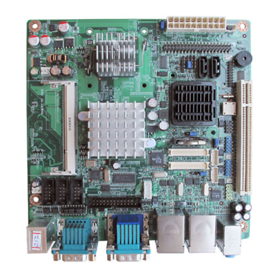
Page 18: Board Layout: Jumper And Connector Locations
HDDLED JFP2 q e t u S P E A K E R SATA1 SATA2 EATXPWR1 q w e r t JFP3 PWR_LED & KEYLOCK Figure 1.1 Jumper and Connector Location Figure 1.2 I/O Connectors AIMB-210 User Manual... -
Page 19: Aimb-210 Board Diagram
AIMB-210 Board Diagram 2nd LVDS (Optional) Figure 1.3 AIMB-210 Board Diagram AIMB-210 User Manual... -
Page 20: Safety Precautions
Caution! There is a danger of a new battery exploding if it is incorrectly installed. Do not attempt to recharge, force open, or heat the battery. Replace the battery only with the same or equivalent type recommended by the man- ufacturer. Discard used batteries according to the manufacturer’s instructions. AIMB-210 User Manual... -
Page 21: Jumper Settings
1-2 closed. This procedure will reset the CMOS to its default setting. Table 1.3: CMOS1 Function Jumper Setting *Keep CMOS data 1-2 closed Clear CMOS data 2-3 closed * Default AIMB-210 User Manual... -
Page 22: Com2 Rs 232/422/485 Mode Selector (Jsetcom2)
(1-2) + (9-11) + (10-12) + (15-17) + (16-18) closed *: Default 1.8.4 JLV1/JLV2: LCD Power 3.3 V/5 V Selector Table 1.5: JLV1/JLV2: LCD Power 3.3 V/5 V Selector Closed Pins Result 1-2* 3.3 V* Default 3.3 V 2-3 closed 1-2 closed AIMB-210 User Manual... -
Page 23: Jpson1: Atx, At Mode Selector
ATX Mode Default ATX Mode AT Mode 2-3 closed 1-2 closed 1.8.6 JWDT1: Watchdog Timer Output Option Table 1.7: JWDT1: Watchdog Timer Output Option Closed Pins Result 2-3* System Reset* Default System Reset 2-3 closed 1-2 closed AIMB-210 User Manual... -
Page 24: System Memory
SODIMM socket. To remove the memory module, just push both handles outward, and the memory mod- ule will be ejected by the mechanism. AIMB-210 User Manual... -
Page 25: Chapter 2 Connecting Peripherals
Chapter Connecting Peripherals... -
Page 26: Introduction
The parallel port is normally used to connect the motherboard to a printer. The AIMB- 210 includes an onboard parallel port, accessed through a 25-pin flat-cable connec- tor, LPT1. Note! Parallel cable is not enclosed in the box as a standard accessory. The order part number is 1700008809. AIMB-210 User Manual... -
Page 27: Primary (Ide1) Ide Connector
Primary (IDE1) IDE Connector AIMB-210 User Manual... -
Page 28: Usb Ports (Lan1_Usb12/Lan2_Usb34/Usb56/Usb78)
1000 Mbps operation. LAN2_USB34 LAN1_USB12 LAN1_USB12 LAN2_USB34 USB56 USB78 Table 2.1: LAN LED Indicator LAN Mode Lan Indicator 1 Gbps Link on LED1 Green on 100 Mbps Link on LED1 Orange on Active LED2 Green flash AIMB-210 User Manual... -
Page 29: Tv-Out Connector (Tvout1)
TV-Out Connector (TVOUT1) Table 2.2: TV-Out Connector (TVOUT1) Signal TV_Pb TV_Y TV_Pr AIMB-210 User Manual... -
Page 30: Vga Connector (Vga1)
VGA Connector (VGA1) The AIMB-210 includes a VGA interface that can drive conventional CRT displays. VGA1 is a standard 15-pin D-SUB connector commonly used for VGA. Pin assign- ments for CRT connector VGA1 are detailed in Appendix B. AIMB-210 User Manual... -
Page 31: Serial Ports (Com1~Com6)
BIOS setup. Different devices implement the RS-232/422/485 standards in different ways. If you are having problems with a serial device, be sure to check the pin assignments for the connector. AIMB-210 User Manual... -
Page 32: Ps/2 Keyboard And Mouse Connector (Kbms1)
PS/2 Keyboard and Mouse Connector (KBMS1) Two 6-pin mini-DIN connectors (KBMS1) on the motherboard provide connection to a PS/2 keyboard and a PS/2 mouse, respectively. AIMB-210 User Manual... -
Page 33: Cpu Fan Connector (Cpu_Fan1)
CPU Fan Connector (CPU_FAN1) If fan is used, this connector supports cooling fans of 500 mA (6 W) or less. AIMB-210 User Manual... -
Page 34: System Fan Connector (Cha_Fan1)
2.10 System FAN Connector (CHA_FAN1) If fan is used, this connector supports cooling fans of 500 mA (6 W) or less. AIMB-210 User Manual... -
Page 35: Front Panel Connectors (Jfp1/Jfp2/Jfp3)
External speaker (JFP2 / SPEAKER) (JFP2 / SPEAKER) is a 4-pin connector for an external speaker. If there is no exter- nal speaker, the AIMB-210 provides an onboard buzzer as an alternative. To enable the buzzer, set pins 3-4 as closed. AIMB-210 User Manual... -
Page 36: Power Led And Keyboard Lock Connector (Jfp3 / Pwr_Led & Key Lock)
PSON1 Connect 1-2 pin cable (On Back plane) 2-3 pin closed 1-2 pin closed with switch Jumper setting System On System Suspend Fast flashes Fast flashes Fast flashes System Off Slow flashes AIMB-210 User Manual... -
Page 37: Line In, Line Out, Mic In Connector (Audio1)
2.12 Line In, Line Out, Mic In Connector (AUDIO1) Line In Line Out Mic In AIMB-210 User Manual... -
Page 38: Serial Ata Interface (Sata1, Sata2)
2.13 Serial ATA Interface (SATA1, SATA2) AIMB-210 features a high performance serial ATA interface (up to 150 MB/s) which eases cabling to hard drives with thin and long cables. AIMB-210 User Manual... -
Page 39: Pci
2.14 The AIMB-210 provides 1 x PCI slot. AIMB-210 User Manual... -
Page 40: Front Headphone Connector (Fpaud1)
I/O module cable to this connector. Note! For motherboards with the optional HD Audio feature, we recommend that you connect a high-definition front panel audio module to this con- nector to avail of the motherboard’s high definition audio capability. AIMB-210 User Manual... -
Page 41: Atx Power Connector (Eatxpwr1)
This connector is for an ATX Micro-Fit power supply. The plugs from the power sup- ply are designed to fit these connectors in only one orientation. Find the proper orien- tation and push down firmly until the connectors completely fit. AIMB-210 User Manual... -
Page 42: Spi Flash Connector(Spi_Cn1)
2.17 SPI Flash connector(SPI_CN1) SPI flash card pin header may be used to flash BIOS if AIMB-210 cannot power on. AIMB-210 User Manual... -
Page 43: Lcd Inverter Connector Inv1 & Inv2 (Optional)
2.18 LCD Inverter Connector INV1 & INV2 (Optional) Note! Signal Description Signal Signal Description Vadj=0.75 V (Recommended: 4.7 K , 1/16 W) ENBKL LCD backlight ON/OFF control signal AIMB-210 User Manual... -
Page 44: Lvds Connector Lvds1 & Lvds2 (Optional)
2.19 LVDS Connector LVDS1 & LVDS2 (Optional) AIMB-210 User Manual... -
Page 45: Digital I/O Connector (Dio1)
2.20 Digital I/O Connector (DIO1) AIMB-210 User Manual... - Page 46 AIMB-210 User Manual...
-
Page 47: Bios Operation
Chapter BIOS Operation... -
Page 48: Introduction
CPUs from 386 through Pentium and AMD Geode™, K7 and K8 (including multiple processor platforms), and VIA Eden C3 and C7 CPU. You can use Advantech’s utilities to select and install features to suit your design needs. BIOS Setup... -
Page 49: Main Menu
Set Password Establish, change or disable password. Save & Exit Setup Save CMOS value settings to CMOS and exit BIOS setup. Exit Without Saving Abandon all CMOS value changes and exit BIOS setup. AIMB-210 User Manual... -
Page 50: Standard Cmos Features
Extended Memory The BIOS POST will determine the amount of extended memory (above 1 MB in CPU’s memory address map) installed in the system. Total Memory This item displays the total system memory size. AIMB-210 User Manual... -
Page 51: Advanced Bios Features
This item controls the speed at which the system registers auto-repeated key- strokes. The eight settings are 6, 8, 10, 12, 15, 20, 24 and 30. – Typematic Delay (Msec) This item sets the keypress time delay before autorepeat begins. AIMB-210 User Manual... -
Page 52: Advanced Chipset Features
This item enables users to set the DRAM RAS# precharge timing, system default is setting to “Auto” to reference the data from SPD ROM. Precharge delay (tRAS) [Auto] This item allows user to adjust memory precharge time. AIMB-210 User Manual... - Page 53 This item allows the user to decide boot display mode. Panel Number This item allows the user to decide display resolution. Init Display First This item is the setting for start up video output: either from PCI Express or Onboard device. AIMB-210 User Manual...
-
Page 54: Integrated Peripherals
This item enables users to set the OnChip IDE device status, including some of new chipsets also support SATA devices (Serial-ATA). Onboard Device This item enables users to set the Onboard device status, including enabling AC97, and LAN devices. AIMB-210 User Manual... - Page 55 This field allows you to select EPP port type 1.7 or 1.9. The choices are “EPP1.9” and “EPP1.7”. ECP Mode Use DMA [3] This item allows user to adjust ECP DMA resource. Onboard Serial port 3 [4F0/IRQ10] This item allows user to adjust serial port 3 of address and IRQ. AIMB-210 User Manual...
-
Page 56: Usb Device Setting
Select “Enabled” if you plan to use a USB keyboard/Mouse. The choices are "Enabled" and "Disabled". USB Storage Function Select "Enabled" if you plan to use an external USB storage device to boot sys- tem under DOS mode. The choices are "Enabled" and "Disabled". AIMB-210 User Manual... -
Page 57: Security Chip Configuration (Optional Item)
Select an item and then press <Enabled> to display the configuration options. Note! To enable the TPM function, set the TPM Support item to [Enabled] and then save the change; after rebooting, the TPM configuration menu will show the active options. AIMB-210 User Manual... -
Page 58: Power Management Setup
Initial display power management signaling. Video Off In Suspend [Yes] This item allows users to turn off video when system is in suspend mode. Suspend Type [Stop Grant] This item allows users to determine the suspend type. AIMB-210 User Manual... - Page 59 Use this to set up the system after power failure. The “Off” setting keeps the sys- tem powered off after power failure, the “On” setting boots up the system after failure, and the “Former-Sts” returns the system to the status before power fail- ure. AIMB-210 User Manual...
-
Page 60: Pnp/Pci Configurations
The commands here are “Auto(ESCD)” or “Manual”. Choosing “Manual” requires you to choose resources from the following sub-menu. “Auto(ESCD)” automatically configures all of the boot and Plug and Play devices, but you must be using Windows 95 or above. AIMB-210 User Manual... -
Page 61: Pc Health Status
VCORE and Other Voltages This shows the voltage of VCORE, +3.3 V, +5 V, +12 V, -12 V, VBAT(V), and 5 VSB (V). 3.2.12 Frequency/Voltage Control Spread Spectrum [Disabled] This item enables users to set the spread spectrum modulation. AIMB-210 User Manual... -
Page 62: Load Setup Defaults
“Setup” requires a password only to enter Setup. “System” requires the pass- word either to enter Setup or to boot the system. A password can be at most 8 characters long. AIMB-210 User Manual... - Page 63 Select Set Password again, and at the “Enter Password” prompt, please don’t enter anything; just press <Enter>. At the”Confirm Password” prompt, again, don’t type in anything; just press <Enter>. Select Save to CMOS and EXIT, type <Y>, then <Enter>. AIMB-210 User Manual...
-
Page 64: Save & Exit Setup
Typing “Y” will quit the BIOS Setup Utility and save user setup values to CMOS. Typing “N” will return to BIOS Setup Utility. 3.2.16 Quit without Saving Note! Typing “Y” will quit the BIOS Setup Utility without saving to CMOS. Typing “N” will return to BIOS Setup Utility. AIMB-210 User Manual... -
Page 65: Chipset Software Installation Utility
Chapter Chipset Software Installation Utility... -
Page 66: Before You Begin
DVD content, and MPEG-2 motion compensation for software DVD Note! This utility is used for the following versions of Windows, and it has to be installed before installing all the other drivers: Windows 2000 Windows XP Windows Vista AIMB-210 User Manual... -
Page 67: Windows Xp Driver Setup
Windows XP Driver Setup Insert the driver CD into your system's CD-ROM drive. You can see the driver folder items. Navigate to the "Drv_INF" folder and click "infinst_autol.exe" to complete the installation of the driver. AIMB-210 User Manual... - Page 68 AIMB-210 User Manual...
-
Page 69: Vga Setup
Chapter VGA Setup... -
Page 70: Introduction
Insert the driver CD into your system's CD-ROM drive. You can see the driver folders items. Navigate to the "Drv_VGA" folder and click "setup.exe" to complete the instal- lation of the drivers for Vista, Windows XP, and Windows 2000. AIMB-210 User Manual... -
Page 71: Lan Configuration
Chapter LAN Configuration... -
Page 72: Introduction
Please find and use the section that provides the driver setup procedure for the operating system you are using. Win XP/Vista Driver Setup (Realtek RTL8111C) Insert the driver CD into your system's CD-ROM drive. Select the Drv_LAN folder then navigate to the directory for your OS. AIMB-210 User Manual... - Page 73 Appendix Programming the Watchdog Timer...
-
Page 74: Appendix A Programming The Watchdog Timer
2F (hex) is the data port. You must first assign the address of register by writing an address value into address port 2E (hex), then write/read data to/from the assigned register through data port 2F (hex). AIMB-210 User Manual... - Page 75 Unlock W83627DHG Select register of watchdog timer Enable the function of the watchdog timer Use the function of the watchdog timer Lock W83627DHG AIMB-210 User Manual...
-
Page 76: Table A.1: Watchdog Timer Registers
Bit 5: Write 1 to generate a timeout signal immedi- ately and automatically return to 0. [default=0] Bit 4: Read status of watchdog timer, 1 means timer is “timeout”. AA (hex) ----- Write this address to I/O port 2E (hex) to lock the watchdog timer 2. AIMB-210 User Manual... -
Page 77: Example Program
Inc dx Mov al,10 Out dx,al ;----------------------------------------------------------- Dec dx ; Lock W83627DHG Mov al,0aah Out dx,al Enable watchdog timer and set 5 minutes as timeout interval ;----------------------------------------------------------- Mov dx,2eh ; Unlock W83627DHG Mov al,87h Out dx,al Out dx,al AIMB-210 User Manual... - Page 78 Enable watchdog timer to be reset by mouse ;----------------------------------------------------------- Mov dx,2eh ; Unlock W83627DHG Mov al,87h Out dx,al Out dx,al ;----------------------------------------------------------- Mov al,07h ; Select registers of watchdog timer Out dx,al Inc dx Mov al,08h Out dx,al ;----------------------------------------------------------- AIMB-210 User Manual...
- Page 79 Dec dx ; Enable the function of watchdog timer Mov al,30h Out dx,al Inc dx Mov al,01h Out dx,al ;----------------------------------------------------------- Dec dx ; Enable watchdog timer to be strobed reset by keyboard Mov al,0f7h Out dx,al Inc dx In al,dx Or al,40h Out dx,al AIMB-210 User Manual...
- Page 80 Dec dx ; Generate a time-out signal Mov al,0f7h Out dx,al ;Write 1 to bit 5 of F7 register Inc dx In al,dx Or al,20h Out dx,al ;----------------------------------------------------------- Dec dx ; Lock W83627DHG Mov al,0aah Out dx,al AIMB-210 User Manual...
-
Page 81: Appendix B I/O Pin Assignments
Appendix I/O Pin Assignments... -
Page 82: Parallel Port (Lpt1)
Parallel Port (LPT1) Table B.1: Parallel Port (LPT1) Signal Signal STROBE* AUTOFD* INIT* SLCTINI* ACK* BUSY SLCT * Low activity USB Header (USB56, USB78) Table B.2: USB Header (USB56) Signal Signal USB0_VCC5 USB1_VCC5 USB0_D- USB1_D- USB0_D+ USB1_D+ AIMB-210 User Manual... -
Page 83: Vga Connector (Vga1)
VGA Connector (VGA1) Table B.3: VGA Connector (VGA1) Signal Signal CRT_VCCIN VGA_G VGA_B V_SDAT H-SYNC V-SYNC V_SCLK RS-232 Interface Table B.4: RS-232 Interface (COM1~COM4) Signal AIMB-210 User Manual... -
Page 84: Rs-232/422/485 Setting Interface (Jetcom2)
RXD485_1 R_SINA RXD422_1 R_SINA RXD232_1 DCDA SOUTA COM1_DCD# COM1_SOUT COM1_TXD485N COM1_RXD485P SINA DTRA COM1_SIN COM1_DTR# COM1_TXD485P COM1_RXD485N SPI_CN1: SPI Fresh Card Pin Connector Table B.6: SPI_CN1:SPI Fresh Card Pin Connector Signal Signal +F1_3V F1_SPI_CS#_Q F1_SPI_CLK_Q F1_SPI_MISO_Q F1_SPI_MOSI_Q AIMB-210 User Manual... -
Page 85: Ps/2 Keyboard And Mouse Connector (Kbms1)
PS/2 Keyboard and Mouse Connector (KBMS1) Table B.7: PS/2 Keyboard and Mouse Connector (KBMS1) Signal KB DATA KB VCC KB CLK M_DATA M_VCC M_CLK CPU Fan Power Connector (CPU_FAN1) Table B.8: CPU Fan Power Connector (CPU_FAN1) Signal +12 V DETECT AIMB-210 User Manual... -
Page 86: System Fan Power Connector (Cha_Fan1)
You can use an LED to indicate when the single board computer is on. Pin 1 of JFP3 supplies the LED's power, and Pin 3 is the ground. Table B.10: Power LED & Keyboard Lock Connector (JFP3) Function LED power (+5 V) KEYLOCK# AIMB-210 User Manual... -
Page 87: Hdd Led And External Speaker Connector (Jfp2/Hdd Led And Speaker)
Table B.11: External Speaker Connector (JFP2/SPEAKER) Signal Signal SPK+ HDDLED+ HDDLED- SPK_IN SMB_DAATA SPK- SMB_CLK B.12 ATX Soft Power Switch and Reset Connector (JFP1/ PWR-SW and RESET) Table B.12: Reset Connector (JFP1/ RESET) Signal PWR_BTN# RESET AIMB-210 User Manual... -
Page 88: Atx Power Connector (Eatxpwr1)
12 V +3.3 V -12 V PSON -5 V +5 V +5 V B.14 USB/LAN ports (LAN1_USB12/LAN2_USB34) Table B.14: USB Port Signal Signal Data0+ Data0- Table B.15: Ethernet 10/100 Mbps RJ-45 Port Signal Signal XMT+ XMT- RCV- RCV+ AIMB-210 User Manual... -
Page 89: Line In, Line Out, Mic In Connector (Audio1)
SATA_0RX- SATA_0RX+ B.17 AT/ATX Mode (PSON1) Table B.17: AT/ATX Mode (PSON1) Signal Signal #PSON_SIO #PSON (to super IO) (to power supply) B.18 AC-97 Audio Interface (FPAUD1) Table B.18: AT/ATX Mode (PSON1) Signal Signal MIC-IN MIC_VCC LOUT_R LOUT_L AIMB-210 User Manual... -
Page 90: Gpio Pin Header (Gpio1)
B.19 GPIO Pin Header (GPIO1) Table B.19: AT/ATX Mode (PSON1) Signal Signal DIO_GP20 DIO_GP10 DIO_GP21 DIO_GP11 DIO_GP22 DIO_GP12 DIO_GP23 DIO_GP13 DIO_GP24 DIO_GP14 DIO_GP25 DIO_GP15 DIO_GP26 DIO_GP16 DIO_GP27 DIO_GP17 SMBCLK_PCI SMBDATA_PCI VCC5_DIO AIMB-210 User Manual... -
Page 91: Lvds Connector: Lvds1 & Lvds2 (Optional)
Signal VDDSAFE_1 VDDSAFE_2 GND_1 GND_7 VDDSAFE_3 VDDSAFE_4 OD0- ED0- OD0+ ED0+ GND_2 GND_8 OD1- ED1- OD1+ ED1+ GND_3 GND_9 OD2- ED2- OD2+ ED2+ GND_4 GND_10 OCK- ECK- OCK+ ECK+ GND_3 GND_11 DDC_CLK DDC_DAT GND_6 GND_12 HPLG VCON AIMB-210 User Manual... -
Page 92: Table B.21:Lvds2 Connector (Optional)
OD2+ ED2+ GND_4 GND_10 OCK- ECK- OCK+ ECK+ GND_3 GND_11 DDC_CLK DDC_DAT GND_6 GND_12 OD3- ED3- OD3+ ED3+ HPLG VCON B.21 LVDS Power Jumper (JLV1, JLV2) * default setting Table B.22: LVDS Power Jumper Signal VCC3 VCC_LCD AIMB-210 User Manual... -
Page 93: Lvds Invert: Inv1 & Inv2 (Optional)
Bisynchronous 1 3B0-3BF Monochrome display and printer adapter (LPT1) 3C0-3CF Reserved 3D0-3DF Color/graphics monitor adapter 3F0-3F7 Diskette controller 3F8-3FF Serial port 1 4E0-4E7 Serial port 4 3E8-3EF Serial port 6 4F0-4F8 Serial port 3 4F8-4FF Serial port 5 AIMB-210 User Manual... -
Page 94: Dma Channel Assignments
1st MB Memory Map Table B.27: 1st MB Memory Map Addr. range (Hex) Device E0000h - FFFFFh BIOS CC000h - DFFFFh Unused C0000h - CBFFFh VGA BIOS A0000h - BFFFFh Video Memory 00000h - 9FFFFh Base memory AIMB-210 User Manual... - Page 95 AIMB-210 User Manual...
- Page 96 No part of this publication may be reproduced in any form or by any means, electronic, photocopying, recording or otherwise, without prior written permis- sion of the publisher. All brand and product names are trademarks or registered trademarks of their respective companies. © Advantech Co., Ltd. 2009...
Need help?
Do you have a question about the AIMB-210 and is the answer not in the manual?
Questions and answers