
Related Manuals for Advantech AIMB-215 B1


Summary of Contents for Advantech AIMB-215 B1
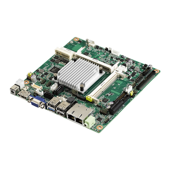
- Page 1 User Manual AIMB-215 B1 Intel® Celeron J1900/N2930/ N2807 Mini-ITX with VGA/LVDS/ DP++ (eDP), 6 COM, Dual LAN, 8 USB, 2 Mini-PCIe, and PCIe x1...
- Page 2 The documentation and the software included with this product are copyrighted 2014 by Advantech Co., Ltd. All rights are reserved. Advantech Co., Ltd. reserves the right to improve the products described in this manual at any time without notice. No part of this manual may be reproduced, copied, translated or transmitted in any form or by any means without prior written permission from Advantech Co., Ltd.
- Page 3 Our dealers are well trained and ready to provide the sup- port required for you to experience the most from your Advantech products. Most of the problems reported are minor and can be easily solved over the phone.
-
Page 4: Declaration Of Conformity
Caution! There is a risk of a new battery exploding if incorrectly installed. Do not attempt to recharge, force open, or heat the battery. Replace the battery only with the same or equivalent type recommended by the manufac- turer. Discard used batteries according to the manufacturer's instruc- tions. AIMB-215 B1 User Manual... -
Page 5: Ordering Information
Memory Compatibility AIMB-215 B1 Memory Compatibility List Brand Size Speed Type Vendor PN Memory Advantech PN Result Tran- DDR3 SODIMM SEC 234 HYK0 TS256MSK64W3N PASS scend 1333 DDR3 K4B2G0846D DDR3 SODIMM MICRON 2XE22 D9QBJ 96SD3L- Apacer 78.B2GCY.AT00C PASS 1333 DDR3... - Page 6 Because of Advantech’s high quality-control standards and rigorous testing, most customers never need to use our repair service. If an Advantech product is defective, it will be repaired or replaced at no charge during the warranty period. For out-of-war- ranty repairs, users will be billed according to the cost of replacement materials, ser- vice time, and freight.
- Page 7 1 x SATA HDD cable 1 x SATA power cable 1 x Serial port cable (1 to 4), for AIMB-215 B1 D/N SKU only 2 x Serial port cable (1 to 1) 1 x I/O port bracket ...
- Page 8 AIMB-215 B1 User Manual viii...
-
Page 9: Table Of Contents
Board Layout: Jumper and Connector Locations........6 Figure 1.1 Jumper and Connector Locations....... 6 Figure 1.2 I/O Connectors ............6 AIMB-215 B1 Board Diagram..............7 Figure 1.3 AIMB-215 B1 Board Diagram ........7 Safety Precautions ..................8 Jumper Options..................9 1.9.1 Setting Jumpers ................ - Page 10 BIOS Setup ..................... 38 3.2.1 Main Menu .................. 39 3.2.2 Advanced BIOS Features ............40 3.2.3 Chipset..................63 3.2.4 Security..................71 3.2.5 Boot .................... 72 3.2.6 Save and Exit................73 Chapter Software and Service Introduction.. 75 Introduction ..................... 76 AIMB-215 B1 User Manual...
- Page 11 RJ45 (LAN1 + LAN2) Connector (LAN12) ..........104 B.16 SPDIF Interface Pin Header (SPDIF_OUT1) ........104 B.17 HD Analog Audio Interface (AUDIO1)........... 105 B.18 Front Panel Audio Pin Header (FPAUD1)..........105 B.19 Audio Amplifier Output Pin Header (JAMP1) (BOM Optional) ....105 AIMB-215 B1 User Manual...
- Page 12 LVDS2 Control Signal Pin Header (LVDS2) (BOM Optional) ....119 B.48 eDP Backlight Inverter Power Connector (INV-EDP1) (BOM Optional) 120 B.49 ATX 12 V Power Supply Connector (ATX12V1) ........120 B.50 SIM Card Holder (SIM2) ............... 120 B.51 RS-485/422 Terminal Resistor Jumper (SW_422_1) ......121 AIMB-215 B1 User Manual...
-
Page 13: Chapter 1 General Information
Chapter General Information... -
Page 14: Introduction
Supports a dual-channel 6 W amplifier (optional) Supports embedded software APIs and utilities OS and BIOS Compatibility The AIMB-215 B1 BIOS supports OS in legacy mode for 32 and 64 bit, and supports OS in UEFI mode for 64-bit. AIMB-215 B1 User Manual... -
Page 15: Specifications
RAM: Up to 8 GB in two-slot 204-pin SODIMM sockets. Supports dual-channel DDR3L (low voltage) SODIMM 1.35 V modules of up to 1333 MHz Note! AIMB-215 B1 supports 1.35 V memory only. Users must install the memory modules on the DIMMA 1 socket first. 1.4.3 Input/Output ... -
Page 16: Industrial Features
Board weight: 0.365 kg Jumpers and Connectors The AIMB-215 B1 motherboard is equipped with connectors for linking the board to external devices such as hard disk drives and a keyboard. The board also features several jumpers for configuring the system according to specific applications. - Page 17 Power LED and keyboard lock pin header JFP3 Power switch/HDD LED/SMBus/Speaker pin JFP1+JFP2 header LVDS2 control signal pin header LVDS2 eDP backlight inverter power connector INV-EDP1 ATX 12-V power supply connector ATX12V1 SIM card holder SIM2 RS-485/422 terminal resistor jumper SW_422_1 AIMB-215 B1 User Manual...
-
Page 18: Board Layout: Jumper And Connector Locations
DIMMB1 USB0708 USB0506 JLVDS1+JLVDS2 SATA_PWR2 JSETCOM6_V1 INV1 JRTCTEST1 GPIO1 COM3/4/5/6 MiniPCIE2 DIMMA1 PSON1 MiniPCIE1 ATX_5VSB1 SYSFAN1 JSETCOM3 SATAPWR1 JCASE1 COM2 KBMS1 JCASEOP_SW1 Figure 1.1 Jumper and Connector Locations USB2 USB4 USB1 USB3 Figure 1.2 I/O Connectors AIMB-215 B1 User Manual... -
Page 19: Aimb-215 B1 Board Diagram
SIM Card holder (colay PCIex1) HD Audio ALC892 PCIe x 1 slot (colay Half-size Mini-PCIe) BIOS Super I/O Winbond Infineon TPM 1.2 NCT6106D (optional) 8-bit GPIO 5 RS-232, 1 RS-232/422/485 Figure 1.3 AIMB-215 B1 Board Diagram AIMB-215 B1 User Manual... -
Page 20: Safety Precautions
Caution! There is a danger of a new battery exploding if incorrectly installed. Do not attempt to recharge, force open, or heat the battery. Replace the battery only with the same or equivalent type recommended by the man- ufacturer. Discard used batteries according to the manufacturer’s instructions. AIMB-215 B1 User Manual... -
Page 21: Jumper Options
1.9.2 CMOS Mode Selection (JRTCTEST1) The AIMB-215 B1 motherboard contains a jumper that can erase CMOS data and reset the system BIOS information. This jumper is typically set with Pins 1 and 2 being closed. To reset the CMOS data, set J1 to Pins 2 and 3 as closed for a few sec- onds before moving the jumper back to Pins 1 and 2 as closed. -
Page 22: Com2 Rs-232/422/485 Mode Selector (Jsetcom3)
Jumper Settings RS-232* (5-6) + (7-9) + (8-10) + (13-15) + (14-16) closed RS-422 (3-4) + (9-11) + (10-12) + (15-17) + (16-18) closed RS-485 (1-2) + (9-11) + (10-12) + (15-17) + (16-18) closed *default AIMB-215 B1 User Manual... -
Page 23: Lvds Panel Voltage Selection (Jlvds1 + Jlvds2)
Set the LVDS panel as +12 V 1.9.5 PSON1: ATX and AT Mode Selector Table 1.6: PSON1: ATX and AT Mode Selector Closed Pins Result AT Mode 2-3* ATX Mode Default ATX Mode AT Mode 2-3 closed 1-2 closed AIMB-215 B1 User Manual... -
Page 24: Jobs1 + Jwdt1: Obs Beep And Watchdog Timer Output
Table 1.8: Case Open Pin Header Selection (JCASEOP_SW1) Function Settings Normal Close (default) Normal Open 1.9.8 Power Switch/HDD LED/SMBus/Speaker Pin Header (JFP1 + JFP2) Table 1.9: Power Switch/HDD LED/SMBus/Speaker Pin Header (JFP1 + JFP2) Function Settings JFP1 (7-10) (default) AIMB-215 B1 User Manual... -
Page 25: Edp Panel Voltage Selection (Jedp1 + Jedp2) (Bom Optional)
+12 V 1.9.10 JEIDA/VESA Selection (JLVDS_VCON1) Table 1.11: JEIDA/VESA Selection (JLVDS_VCON1) Function Settings Pull high to +V5. (JEIDA or VESA base on panel definition) Pull down to GND (default) (JEIDA or VESA base on panel definition) AIMB-215 B1 User Manual... -
Page 26: Rs-485/422 Terminal Resistor Jumper (Sw_422_1)
1.9.11 RS-485/422 Terminal Resistor Jumper (SW_422_1) Table 1.12: RS-485/422 Terminal Resistor Jumper (SW_422_1) Function Settings Default Add RS-485 terminator Add RS-422 terminator AIMB-215 B1 User Manual... -
Page 27: Chapter 2 Connecting Peripherals
Chapter Connecting Peripherals... -
Page 28: Introduction
LAN and USB Ports (LAN1/2, USB0102/ USB0304/USB0506/USB0708) AIMB-215 B1 provides up to seven USB 2.0 and one USB 3.0 ports. One USB 3.0 and three USB 2.0 are located on the rear side. The USB interface complies with the USB specification revision 2.0 that supports transmission rates of up to 480 Mbps, and revision 3.0 that supports transmission rates of up to 5 Gbps, and is also fuse... -
Page 29: Vga Connector (Vga1)
VGA Connector (VGA1) VGA1 is a standard 15-pin D-SUB connector commonly used for VGA. The pin assignments for VGA are detailed in Appendix B. AIMB-215 B1 User Manual... -
Page 30: Serial Ports (Com1 ~ Com6)
Serial Ports (COM1 ~ COM6) AIMB-215 B1 supports six serial ports. COM3 is RS-232/422/485 and COM1/2/4/5/6 are RS-232. COM6 also supports 5 V/12 V according to jumper selection. Users can employ JSETCOM3 to select between the RS-232/422/485 modes for COM3. Such ports can be connected to serial devices, such as a mouse or printer, or to a commu- nications network. -
Page 31: Ps/2 Keyboard And Mouse Connector (Kbms1)
PS/2 Keyboard and Mouse Connector (KBMS1) Onboard six-pin wafer box connector, which supports one standard PS/2 keyboard and one standard PS/2 mouse. Display Port Connector (DP1) AIMB-215 B1 User Manual... -
Page 32: System Fan Connector (Sysfan1/2)
For devices with a fan installed, this connector supports cooling fans of up to 500 mA (6 W). Front Panel Connectors (JFP3/JFP1 + JFP2) Several external switches are provided for monitoring and controlling the AIMB-215 JFP3 JFP1+JFP2 AIMB-215 B1 User Manual... -
Page 33: Atx Soft Power Switch (Jfp1 + Jfp2/Pwr_Sw)
External Speaker (JFP1 + JFP2/SPEAKER) (JFP1 + JFP2/SPEAKER) is a four-pin connector for an external speaker. If no exter- nal speaker is available, the AIMB-215 B1 provides an onboard buzzer as an alterna- tive. To enable the buzzer, set Pins 7-10 as closed. -
Page 34: Line-Out Connector (Audio1)
Line-Out Connector (AUDIO1) AUDIO1 This connector supports line-out, mic-in, and line-in functions. 2.10 Serial ATA Interface (SATA1/2) & SATADOM Power Pin Header (JSATAPWR1) SATA1 SATA2 JSATAPWR1 AIMB-215 B1 User Manual... -
Page 35: Pci-Express X1 Slot (Pciex1_1)
AIMB-215 B1 features a high-performance Serial ATA interface (up to 300 MB/s) that allows cabling to hard drives using long, thin cables. Note! SATA2 is only supported when mSATA is not in use. SATA2 and mSATA cannot be used concurrently. -
Page 36: Front Panel Audio Connector (Fpaudio1)
This connector is for an ATX Micro-Fit power supply. The plugs from the power sup- ply are designed to fit these connectors in only one direction. Determine the correct orientation and press firmly until the connectors mate completely. ATX12V1 AIMB-215 B1 User Manual... -
Page 37: Spi Flash Connector(Spi_Cn1)
2.14 SPI Flash Connector(SPI_CN1) The SPI flash card pin header may be used to flash the BIOS if the AIMB-215 B1 cannot be powered on. SPI_CN1 2.15 LVDS Backlight Inverter Power Connector (INV1) INV1 AIMB-215 B1 User Manual... -
Page 38: Lvds Connector (Lvds1)
Note! Signal Description Signal Signal Description Vadj=0.75 V (Recommended: 4.7 KΩ, >1/16 W) ENBKL LCD backlight ON/OFF control signal 2.16 LVDS Connector (LVDS1) LVDS1 Pin 3: GND → Panel connected NC/3.3 V → No panel AIMB-215 B1 User Manual... -
Page 39: General Purpose I/O Connector (Gpio1)
2.17 General Purpose I/O Connector (GPIO1) GPIO1 2.18 CMOS Battery Wafer Box (BAT1) BAT1 AIMB-215 B1 User Manual... -
Page 40: Spi Bios Socket (Spi1)
2.19 SPI BIOS Socket (SPI1) SPI1 2.20 SPDIF Interface Pin Header (SPDIF_OUT1) SPDIF_OUT1 AIMB-215 B1 User Manual... -
Page 41: Audio Amplifier Output Pin Header (Jamp1) (Bom Optional)
2.21 Audio Amplifier Output Pin Header (JAMP1) (BOM Optional) JAMP1 2.22 ATX Power Supply (5VSB) Connector (ATX_5VSB1) ATX_5VSB1 AIMB-215 B1 User Manual... -
Page 42: Sata Power Connector (Sata_Pwr1/2)
2.23 SATA Power Connector (SATA_PWR1/2) SATA_PWR1 SATA_PWR2 2.24 Case Open Pin Header (JCASE1) JCASE1 AIMB-215 B1 User Manual... -
Page 43: Ddr3L Sodimm Socket (Dimma1/B1)
DIMMB1 DIMMA1 Note! AIMB-215 B1 supports 1.35 V memory only. Users must populate the memory on socket DIMMA1 first. Users are advised to use memory modules of the same type, speed, and frequency for each motherboard. Memory modules of different types and speeds should not be used. -
Page 44: Mini-Pcie And Msata Connector (Minipcie1)
2.26 Mini-PCIe and mSATA Connector (MINIPCIE1) MINIPCIE1 2.27 Mini-PCIe Connector (MINIPCIE2) MINIPCIE2 AIMB-215 B1 User Manual... -
Page 45: Low Pin Count Interface Header (Lpc1)
2.28 Low Pin Count Interface Header (LPC1) 2.29 RTC Reset Pin Header (JRTCTEST1) JRTCTEST1 AIMB-215 B1 User Manual... -
Page 46: Edp Connector (Edp1) (Bom Optional)
2.30 eDP Connector (eDP1) (BOM Optional) eDP1 2.31 eDP Backlight Inverter Power Connector (INV- EDP1) (BOM Optional) INV-EDP1 AIMB-215 B1 User Manual... -
Page 47: Sim Card Holder (Sim2)
2.32 SIM Card Holder (SIM2) SIM2 AIMB-215 B1 User Manual... - Page 48 AIMB-215 B1 User Manual...
-
Page 49: Bios Operation
Chapter BIOS Operation... -
Page 50: Introduction
AIMB-215 B1 BIOS setup menu pages. BIOS Setup The AIMB-215 B1 Series is equipped with built-in AMI BIOS and a CMOS Setup Util- ity that allows users to configure specific settings or activate certain system features. -
Page 51: Main Menu
System Date using the <Arrow> keys. Enter new values via the keyboard. Press the <Tab> or <Arrow> keys to move between fields. The date must be entered in MM/DD/YY format. The time must be entered in HH:MM:SS format. AIMB-215 B1 User Manual... -
Page 52: Advanced Bios Features
3.2.2 Advanced BIOS Features Select the Advanced tab from the AIMB-215 B1 Setup menu to enter the Advanced BIOS Setup page. Users can select any item in the left frame of the screen, such as CPU Configuration, to access the submenu for that item. Select an Advanced BIOS Setup option by highlighting the text using the <Arrow>... - Page 53 TPM Enabled Status Provides the current capability state of the security device. TPM Active Status Provides the current capability state of the security device. TPM Owner Status Provides current Ownership state. ie: Owned or Unowned. AIMB-215 B1 User Manual...
- Page 54 This item allows users to enable or disable hibernation. ACPI Sleep State This item allows users to set the ACPI sleep state. Lock Legacy Resources This item allows users to lock legacy device resources. AIMB-215 B1 User Manual...
- Page 55 3.2.2.3 Super IO Configuration AIMB-215 B1 User Manual...
- Page 56 AIMB-215 B1 User Manual...
- Page 57 AIMB-215 B1 User Manual...
- Page 58 Serial Ports 1/2/3/4/5/6 This item allows users to enable or disable serial Ports 1/2/3/4/5/6. Change Settings This item allows users to change the settings for serial Ports 1/2/3/4/5/6. AIMB-215 B1 User Manual...
- Page 59 3.2.2.4 PC Health Status This page shows the AIMB-215 B1 PC health status. Smart Fan Function This item allows users to enable or disable the System Smart Fan function. CPU Warning Temperature This item allows users to set the CPU temperature threshold. When the system CPU reaches the threshold temperature, a buzzer will emit a warning alert.
- Page 60 3.2.2.5 Smart Fan Mode Configuration This page shows the Smart Fan Mode items. Smart Fan Mode This item allows users to enable or disable Smart Fan mode. AIMB-215 B1 User Manual...
- Page 61 3.2.2.6 Digital I/O Configuration Digital I/O Configuration This item allows users to set digital I/O 1 to 8 as inputs or outputs. 3.2.2.7 ISCT Support AIMB-215 B1 User Manual...
- Page 62 ISCT Support This item allows users to enable or disable ISCT support. 3.2.2.8 S5 RTC Wake Settings Wake System From S5 This item allows users to enable or disable system wake on alarm event. AIMB-215 B1 User Manual...
- Page 63 3.2.2.9 Serial Port Console Redirection Console Redirection This item allows users to enable or disable console redirection. AIMB-215 B1 User Manual...
- Page 64 This item allows users to enable or disable the Execute Disable Bit function. Intel Virtualization Technology This item allows users to enable or disable Intel® Virtualization Technology. Power Technology Enable the power management features. AIMB-215 B1 User Manual...
- Page 65 This page shows the CPU information. 3.2.2.11 PPM Configuration EIST To enable or disable Intel SpeedStep. CPU C state Report To enable or disable CPU C state report to OS. AIMB-215 B1 User Manual...
- Page 66 Serial-ATA Port 2 This item allows users to enable or disable the Serial-ATA Port 2 / mSATA device. SATA Port 2 Hot Plug This item allows users to enable or disable the SATA Port 2 hot plug. AIMB-215 B1 User Manual...
- Page 67 PCI Express Dynamic Clock Gating This item allows users to enable or disable the PCI Express Dynamic Clock Gat- ing function. OS Selection This item allows users to set the OS as Windows 7 or Windows 8.x. AIMB-215 B1 User Manual...
- Page 68 This item allows users to enable or disable 64-bit-capable device decoding in above 4G address spaces (if the system supports 64-bit PCI decoding). SR-I0V Support If the system has SR-IOV-capable PCIe devices, this item allows users to enable or disable single root IO virtualization support. AIMB-215 B1 User Manual...
- Page 69 “Link Training” bit in the link status register. Values range from 10 to 10000 uS. Unpopulated Links To save power, the software will disable unpopulated PCI Express links if this option set as “Disable Link”. AIMB-215 B1 User Manual...
- Page 70 Bus Master Enable bit is in the Command Register Set. AtomicOp Egress Blocking If supported by the hardware and set to “Enabled”, outbound AtomicOp requests transmitted via egress ports will be blocked. AIMB-215 B1 User Manual...
- Page 71 Hardware Autonomous Speed If supported by the hardware and set to “Disabled”, the ability to alter link speed using the hardware is disabled, except by reducing the speed to correct unsta- ble link operation. AIMB-215 B1 User Manual...
- Page 72 Controls the execution of UEFI and Legacy Storage OpROM. – Video Controls the execution of UEFI and Legacy Video OpROM. – Other PCI devices Determines the OpROM execution policy for devices other than network, storage, and/or video devices. AIMB-215 B1 User Manual...
- Page 73 CDROMs, and drives with no media are emulated according to the drive type. Note! When the selected OS is Windows 7, users must install a USB 3.0 XHCI driver. Please refer to Chapter 8 for information on XHCI driver installation. AIMB-215 B1 User Manual...
- Page 74 This item allows users to enable or disable the BIOS AT code from running. Enter Intel® AT Suspend Mode This item allows users to request that a platform enter AT Suspend mode (this option is only available when AT enrolled). AIMB-215 B1 User Manual...
-
Page 75: Chipset
3.2.3 Chipset This page provides information of the chipset on AIMB-215 B1. North Bridge This item provides details of the North Bridge parameters. South Bridge This item provides details of the South Bridge parameters. AIMB-215 B1 User Manual... - Page 76 Max TOLUD This item allows users to select the maximum TOLUD. GOP and Intel IGD Configuration AIMB-215 B1 User Manual...
- Page 77 This item allows users to enable or disable ISP PCI device selection. VCC and VNN Configuration for Power State 2: Vcc_Vnn Config for Power State 2 This item allows users to enable or disable VCC and VNN Configuration for Power State 2. AIMB-215 B1 User Manual...
- Page 78 Graphics Power Management Control RC6 (Render Standby) This item allows users to enable render standby support. LCD Control AIMB-215 B1 User Manual...
- Page 79 IGFX Clone modes) Boot Display Boot Display PASS Only Primary. PASS LVDS PASS Only Primary. PASS LVDS PASS Only Primary. PASS Azalia HD Audio This item allows users to adjust the Azalia HD audio options. AIMB-215 B1 User Manual...
- Page 80 This item allows users to enable or disable BIOS Read/Write Protection. SATA Port 2/mSATA This item allows users to specify SATA Port 2 or mSATA for use. PCIE Slot/mPCIE This item allows users to specify PCIEx1 Port or miniPCIe2 for use. Audio Configuration AIMB-215 B1 User Manual...
- Page 81 This item allows users to enable or disable USB 2.0 (EHCI) support. Note! When the selected OS is Windows 7, users must install a USB 3.0 XHCI driver. Please refer to Chapter 8 for information on XHCI driver installation. AIMB-215 B1 User Manual...
- Page 82 This item allows users to enable or disable the PCI Express port slot. Hot Plug This item allows users to enable or disable the PCI Express hot plug. Speed This item allows users to configure the PCIe port speed. AIMB-215 B1 User Manual...
-
Page 83: Security
3.2.4 Security Select the Security tab from the AIMB-215 B1 BIOS Setup Utility main setup menu. All Security options, such as password protection and virus protection, are described in this section. To access the submenus for the “Change Administrator” and “User Password”... -
Page 84: Boot
This item allows users to enable or disable boot initialization with the minimum number of devices necessary to launch the active boot option. These settings have no effects for BBS boot options. Boot Option Priorities This item allows users to set the system boot order. AIMB-215 B1 User Manual... -
Page 85: Save And Exit
This item allows users to override boot priority with a selected boot device. Launch EFI Shell From a File system Device This item allows users to launch an EFI Shell application (Shellx64.efi) from an available file system device. AIMB-215 B1 User Manual... - Page 86 AIMB-215 B1 User Manual...
-
Page 87: Software And Service Introduction
Chapter Software and Service Introduction... -
Page 88: Introduction
Introduction The mission of Advantech Embedded Software Services is to “enhance users’ quality of life with Advantech platforms and Microsoft® Windows® embedded technology”. We equip Advantech platforms with Windows® embedded software products to more effectively support the embedded computing community. This eliminates the hassle of dealing with multiple vendors (hardware suppliers, system integrators, and embed- ded OS distributors) for specific projects. - Page 89 CPU speed according to the system load. System Throttling This refers to a series of methods for reducing system power consumption by lowering the clock frequency. This API allows users to adjust the clock frequency from 87.5% to 12.5%. AIMB-215 B1 User Manual...
-
Page 90: Software Utility
CPU and system temperature, and fan speed. These system values are crucial. If critical errors occur and are not solved imme- diately, permanent damage to the device may result. AIMB-215 B1 User Manual... - Page 91 Chapter Chipset Software Install Utility...
-
Page 92: Before Installation
Before installing the enhanced display drivers and utility software, please read the instructions provided in this chapter carefully. The drivers for AIMB-215 B1 are pro- vided on the software installation CD. This driver will guide and link users to the utili- ties and drivers required for Microsoft Windows-based systems. -
Page 93: Chapter 6 Vga Setup
Chapter VGA Setup... -
Page 94: Introduction
See Chapter 5 for information regarding installing the CSI utility. Insert the driver CD into the system CD-ROM drive to access the driver folder items. Navigate to the “VGA” folder and click “setup.exe” to initiate the installation of drivers for Windows 7 and Windows 8.1. AIMB-215 B1 User Manual... -
Page 95: Chapter 7 Lan Configuration
Chapter LAN Configuration... -
Page 96: Introduction
Introduction The AIMB-215 B1 system features dual Gigabit Ethernet LANs via dedicated PCI Express x1 lanes (Realtek RTL8111E (LAN1) and Realtek RTL8111E (LAN2)) that offer a bandwidth of up to 500 MB/sec, eliminating bottlenecks in the flow of network data by incorporating Gigabit Ethernet at 1000 Mbps. - Page 97 Chapter XHCI Driver Installation...
-
Page 98: Introduction
Introduction The XHCI driver is only built into the Window 8.x OS, not Windows 7. If the selected OS is Windows 7, users must install the USB 3.0 XHCI driver. AIMB-215 B1 User Manual... -
Page 99: Chapter 8 Xhci Driver Installation
For systems with Windows 7 as the OS, only USB 1/2/5/6 are opera- tional prior to the USB 3.0 XHCI driver installation. Users must install the USB 3.0 XHCI driver to ensure all USB ports are operational. AIMB-215 B1 User Manual... - Page 100 AIMB-215 B1 User Manual...
- Page 101 Appendix Programming the Watchdog Timer...
-
Page 102: A.1 Programming The Watchdog Timer
Programming the Watchdog Timer The AIMB-215 B1 watchdog timer can be used to monitor system software opera- tions and execute corrective actions if the software fails to function within the pro- grammed period. The operations and procedures for programming the watchdog timer are described in this section. - Page 103 Unlock NCT6106D Select a register for the watchdog timer Enable the function of the watchdog timer Use the function of the watchdog timer Lock NCT6106D AIMB-215 B1 User Manual...
-
Page 104: Table A.1: Watchdog Timer Registers
0 (default = Bit 4: Read the watchdog timer status, 1 means the timer has reach timeout. AA (hex) ----- Write this address to I/O port 2E (hex) to lock the watchdog timer. AIMB-215 B1 User Manual... -
Page 105: A.1.3 Example Program
Mov al,10 Out dx,al ;----------------------------------------------------------- Dec dx; lock NCT6106D Mov al,0aah Out dx,al Enable the watchdog timer and set the timeout interval as 5 minutes ;----------------------------------------------------------- Mov dx,2eh; unlock NCT6106D Mov al,87h Out dx,al Out dx,al AIMB-215 B1 User Manual... - Page 106 Enable the watchdog timer to be reset using a mouse ;----------------------------------------------------------- Mov dx,2eh; unlock NCT6106D Mov al,87h Out dx,al Out dx,al ;----------------------------------------------------------- Mov al,07h; select the watchdog timer registers Out dx,al Inc dx Mov al,08h Out dx,al ;----------------------------------------------------------- AIMB-215 B1 User Manual...
- Page 107 Mov al,30h Out dx,al Inc dx Mov al,01h Out dx,al ;----------------------------------------------------------- Dec dx; enable the watchdog timer to be strobed reset using a keyboard Mov al,0f2h Out dx,al Inc dx In al,dx Or al,40h Out dx,al AIMB-215 B1 User Manual...
- Page 108 ;----------------------------------------------------------- Dec dx; generate a timeout signal Mov al,0f2h Out dx,al; write 1 to Bit 5 of Register F7 Inc dx In al,dx Or al,20h Out dx,al ;----------------------------------------------------------- Dec dx; lock NCT6106D Mov al,0aah Out dx,al AIMB-215 B1 User Manual...
- Page 109 Appendix I/O Pin Assignments...
-
Page 110: B.1 Dc-In Adaptor Connector (Dcin1)
DC-IN Adaptor Connector (DCIN1) Signal Signal Display Port Connector (DP1) Signal Signal ML_LANE0+ ML_LANE0- ML_LANE1+ ML_LANE1- ML_LANE2+ ML_LANE2- ML_LANE3+ ML_LANE3- Config 1 AUX_CH+ AUX_CH- Hot Plug Detect +3.3V AIMB-215 B1 User Manual... -
Page 111: B.3 Edp Panel Voltage Selection (Jedp-1 + Jedp-2) (Bom Optional)
Panel Voltage Selection (JEDP-1 + JEDP-2) (BOM Optional) JEDP-1 Signal Signal +V12 JEDP-2 Signal Signal +V3.3 VCC_eDP VGA Connector (VGA1) Signal Signal GREEN SGND BLUE N.C. HSYNC RED GND VSYNC GREEN GND BLUE GND AIMB-215 B1 User Manual... -
Page 112: B.5 Serial Ata Interface Connector (Sata2)
Serial ATA Interface Connector (SATA2) Signal Signal SATADOM Power Pin Header (JSATAPWR1) Signal SATA_DOM Serial ATA Interface Connector (SATA1) Signal Signal AIMB-215 B1 User Manual... -
Page 113: B.8 Cmos Battery Wafer Box (Bat1)
Signal Signal VBAT System Fan Connector (SYSFAN2) Signal Signal FAN SPEED VCC_FAN B.10 USB3.0 + USB2.0 Stack Connector (USB0102) USB02 USB01 Signal Signal VBUS_2 StdA_SSTX- D-_2 StdA_SSTX+ D+_2 VBUS_1 GND_2 D-_1 StdA_SSRX- D+_1 StdA_SSRX+ GND_1 GND_DRAIN AIMB-215 B1 User Manual... -
Page 114: B.11 Spi Bios Socket (Spi1)
B.11 SPI BIOS Socket (SPI1) Signal Signal HOLD# VCC_SPI B.12 USB2.0 * 2 Stack Connector (USB0304) USB04 USB03 Signal Signal VCC_USB0 VCC_USB1 USB-0_B USB-1_B USB+0_B USB+1_B GND_1 GND_2 AIMB-215 B1 User Manual... -
Page 115: B.13 Com1 Box Header (Com1)
B.13 COM1 Box Header (COM1) Signal Signal DCD# DSR# RTS# SOUT CTS# DTR# B.14 Watchdog Timer Output and OBS Beep (JOBS1 + JWDT1) Signal RESET# SIO BEEP FRP BEEP AIMB-215 B1 User Manual... -
Page 116: B.15 Rj45 (Lan1 + Lan2) Connector (Lan12)
B.15 RJ45 (LAN1 + LAN2) Connector (LAN12) Signal Signal LAN1_MID0+ LAN2_MID0+ LAN1_MID0- LAN2_MID0- LAN1_MID1+ LAN2_MID1+ LAN1_MID1- LAN2_MID1- LAN1_MID2+ LAN2_MID2+ LAN1_MID2- LAN2_MID2- LAN1_MID3+ LAN2_MID3+ LAN1_MID3- LAN2_MID3- B.16 SPDIF Interface Pin Header (SPDIF_OUT1) Signal SPDIF OUT AIMB-215 B1 User Manual... -
Page 117: B.17 Hd Analog Audio Interface (Audio1)
Front Panel Audio Pin Header (FPAUD1) Signal Signal MIC IN-L MIC IN-R FPAUD_DETECT# LINE OUT-R SENSE R1 SENSE LINE OUT-L SENSE R2 B.19 Audio Amplifier Output Pin Header (JAMP1) (BOM Optional) Signal AMP_OUT-L AMP_OUT+L AMP_OUT-R AMP_OUT+R AIMB-215 B1 User Manual... -
Page 118: B.20 Lvds Vesa And Jeida Format Pin Header
Signal +V3.3 LVDS1_VCON B.21 LVDS Panel Connector (LVDS1) Signal Signal LVDS DETECT# OD0- ED0- OD0+ ED0+ OD1- ED1- OD1+ ED1+ OD2- ED2- OD2+ ED2+ OCK- ECK- OCK+ ECK+ DDC CLK DDC DAT OD3- ED3- OD3+ ED3+ AIMB-215 B1 User Manual... -
Page 119: B.22 Dual-Port Usb2.0 Box Header (Usb0506)
NC/3.3 V → No panel B.22 Dual-Port USB2.0 Box Header (USB0506) Signal Signal VCC_USB1 VCC_USB2 USB1- USB2- USB1+ USB2+ B.23 LVDS Panel Voltage Selection (JLVDS1 + JLVDS2) JLVDS1 Signal Signal +V12 JLVDS2 Signal Signal +V3.3 VCC_LVDS AIMB-215 B1 User Manual... -
Page 120: B.24 Com6 Ri# Selection Pin Header (Jsetcom6_V1)
Signal Signal RI#_VCON RI#_VCON +12V RI#_VCON B.25 LVDS Backlight Inverter Power Connector (INV1) Signal Signal +V12 Backlight CTRL Backlight EN B.26 8-bit General Purpose I/O Pin Header (GPIO1) Signal Signal SIO_GPIO0 SIO_GPIO4 SIO_GPIO1 SIO_GPIO5 SIO_GPIO2 SIO_GPIO6 AIMB-215 B1 User Manual... -
Page 121: B.27 Com3 ~ Com6 Box Header (Com3456)
DTR# [4] RI [4] DCD# [5] DSR# [5] RXD [5] RST# [5] TXD [5] CTS# [5] DTR# [5] RI [5] DCD# [6] DSR# [6] RXD [6] RST# [6] TXD [6] CTS# [6] DTR# [6] RI [6] AIMB-215 B1 User Manual... -
Page 122: B.28 At/Atx Mode Selection (Pson1)
B.28 AT/ATX Mode Selection (PSON1) Signal VCCAT +3.3V VCCATX B.29 ATX Power Supply(5VSB) Connector (ATX_5VSB1) Signal +V5SB PS_ON# AIMB-215 B1 User Manual... -
Page 123: B.31 Sata Power Connector (Sata_Pwr1)
COM3 RS232, RS422, and RS485 Selection Pin Header (JSETCOM3) Signal Signal RX_485 RX_422 RX_232 DCD [3] SOUT [3] DCD# [3] COM_SOUT [3] TX_485- RX_485+ SIN [3] DTR [3] COM_SIN [3] DTR# [3] TX_485+ RX_485- B.31 SATA Power Connector (SATA_PWR1) Signal Signal +V12 AIMB-215 B1 User Manual... -
Page 124: B.32 Com2 Pin Header (Com2)
B.32 COM2 Pin Header (COM2) Signal Signal DCD# DSR# RTS# SOUT CTS# DTR# B.33 System Fan Connector (SYSFAN1) Signal Signal FAN SPEED VCC_FAN B.34 Case Open Selection Pin Header (JCASEOP_SW1) Signal CASEOP# HWM_CASEOP# CASEOP AIMB-215 B1 User Manual... -
Page 125: B.35 Case Open Pin Header (Jcase1)
B.35 Case Open Pin Header (JCASE1) Signal CASEOP B.36 PS/2 Keyboard and PS/2 Mouse Connector (KBMS1) Signal Signal KB_CLK# KB_DAT# VCC_KBMS MS_CLK# MS_DAT# AIMB-215 B1 User Manual... -
Page 126: B.37 Mini-Pcie Connector (Minipcie2)
SIM_PWR SIM_DATA REFCLK- SIM_CLK REFCLK+ SIM_RESET SIM_VPP Reserved Reserved DISABLE# DETECT# RESET# PCIE_RX+ +3.3Vaux PCIE_RX- +1.5V SMB_CLK PCIE_TX- SMB_DATA PCIE_TX+ Reserved USB_D- Reserved USB_D+ Reserved Reserved Reserved Reserved LED_WLAN# Reserved Reserved Reserved +1.5V Reserved Reserved +3.3V AIMB-215 B1 User Manual... -
Page 127: B.38 Mini-Pcie And Msata Connector (Minipcie1)
CLKREQ# Reserved Reserved REFCLK- Reserved REFCLK+ Reserved Reserved Reserved Reserved DISABLE# DETECT# RESET# PCIE_RX+ +3.3Vaux PCIE_RX- +1.5V SMB_CLK PCIE_TX- SMB_DATA PCIE_TX+ USB_D- USB_D+ +3.3Vaux +3.3Vaux Reserved V1.2_DETECT# LED_WLAN# Reserved Reserved Reserved +1.5 V Reserved MSATA_DETECT# +3.3Vaux AIMB-215 B1 User Manual... -
Page 128: B.39 Low Pin Count Interface Header (Lpc1)
SMB_CLK SMB_DATA Reserved Reserved +3.3V +3.3V Reserved Reserved Reserved Reserved Reserved Reserved +1.5V Reserved MSATA_DETECT# +3.3V B.39 Low Pin Count Interface Header (LPC1) Signal Signal LPC CLK RESET# FRAME# +V3.3 SMBus CLK SERIRQ SMBus DAT +V5SB AIMB-215 B1 User Manual... -
Page 129: B.40 Bios Flash Pin Header (Spi_Cn1)
B.40 BIOS Flash Pin Header (SPI_CN1) Signal Signal SPI_CS# SPI_CLK SPI_MISO SPI_MOSI B.41 RTC Reset Pin Header (JRTCTEST1) Signal RTC RESET# B.42 SATA Power Connector (SATA_PWR2) Signal Signal +V12 AIMB-215 B1 User Manual... -
Page 130: B.43 Dual-Port Usb2.0 Pin Header (Usb0708)
B.43 Dual-Port USB2.0 Pin Header (USB0708) Signal Signal VCC_USB1 VCC_USB2 USB1- USB2- USB1+ USB2+ B.44 eDP Connector (eDP1) (BOM Optional) Signal Signal EDP0- EDP3- EDP0+ EDP3+ EDP1- EDP1+ EAUX- EAUX+ EDP2- EDP2+ DP_HPD VDD_EDP VDD_EDP AIMB-215 B1 User Manual... -
Page 131: B.45 Power Led And Keyboard Lock Pin Header (Jfp3)
Signal SPK_P3 HDD LED+ SMB_DATA Power Button+ System Reset+ SPK_P2 SPK_P4 HDD LED- SMB_CLK Power Button- System Reset- B.47 LVDS2 Control Signal Pin Header (LVDS2) (BOM Optional) Signal Signal LVDS2_BKLTEN LVDS2_GPIO3 LVDS2_VDD_EN LVDS2_GPIO2 LVDS2_RST# LVDS2_GPIO1 LVDS2_GPIO0 AIMB-215 B1 User Manual... -
Page 132: B.48 Edp Backlight Inverter Power Connector (Inv-Edp1) (Bom Optional)
Backlight Inverter Power Connector (INV- EDP1) (BOM Optional) Signal Signal +V12 Backlight CTRL Backlight EN B.49 ATX 12 V Power Supply Connector (ATX12V1) Signal Signal B.50 SIM Card Holder (SIM2) Signal Signal UIM_PWR UIM_RESET UIM_VPP UIM_CLK UIM_DATA Reserved Reserved AIMB-215 B1 User Manual... -
Page 133: B.51 Rs-485/422 Terminal Resistor Jumper (Sw_422_1)
B.51 RS-485/422 Terminal Resistor Jumper (SW_422_1) Signal Signal COM3_TXD485P Pull-up terminator (+V5) Pull-down terminator COM3_TXD485N (GND) Pull-down terminator COM3_RXD422N (GND) COM3_RXD422P Pull-up terminator (+V5) AIMB-215 B1 User Manual... - Page 134 No part of this publication may be reproduced in any form or by any means, electronic, photocopying, recording or otherwise, without prior written permis- sion from the publisher. All brand and product names are trademarks or registered trademarks of their respective companies. © Advantech Co., Ltd. 2014...
Need help?
Do you have a question about the AIMB-215 B1 and is the answer not in the manual?
Questions and answers