Table of Contents
Advertisement
Quick Links
Manual
ADVANTECH
AIMB-285
The information contained in this document has been carefully researched and is, to the best
of our knowledge, accurate. However, we assume no liability for any product failures or
damages, immediate or consequential, resulting from the use of the information provided
herein. Our products are not intended for use in systems in which failures of product could
result in personal injury. All trademarks mentioned herein are property of their respective
owners. All specifications are subject to change without notice.
Advertisement
Table of Contents

Related Manuals for Advantech AIMB-285


Summary of Contents for Advantech AIMB-285
- Page 1 Manual ADVANTECH AIMB-285 The information contained in this document has been carefully researched and is, to the best of our knowledge, accurate. However, we assume no liability for any product failures or damages, immediate or consequential, resulting from the use of the information provided herein.
- Page 2 User Manual AIMB-285 Intel® Core™ i7/i5/i3/Pentium/ Celeron LGA 1151 Mini-ITX with DP++/HDMI/VGA, 2 COM, Dual LAN, PCIe x4, miniPCIe, DDR4, DC Input...
- Page 3 No part of this manual may be reproduced, copied, translated or transmitted in any form or by any means without the prior written permission of Advantech Co., Ltd. Information provided in this manual is intended to be accurate and reliable. How- ever, Advantech Co., Ltd.
- Page 4 Whether your new Advantech equipment is destined for the labo- ratory or the factory floor, you can be assured that your product will provide the reliability and ease of operation for which the name Advantech has come to be known.
-
Page 5: Declaration Of Conformity
Discard used batteries according to the manufacturer's instructions. CPU Compatibility Processor_Number Power(watt) Cache ES/QS/MP Package type i3-6100 LGA1151 i3-6100TE LGA1151 i5-6400 LGA1151 i5-6500 LGA1151 i5-6500TE LGA1151 i5-6600 LGA1151 I5-6600K LGA1151 i7-6700 LGA1151 i7-6700TE LGA1151 I7-6700K LGA1151 Pentium G4400 LGA1151 AIMB-285 User Manual... -
Page 6: Ordering Information
Because of Advantech’s high quality-control standards and rigorous testing, most of our customers never need to use our repair service. If an Advantech product is defec- tive, it will be repaired or replaced at no charge during the warranty period. For out- of-warranty repairs, you will be billed according to the cost of replacement materials, service time and freight. - Page 7 It should be free of marks and scratches and in perfect working order upon receipt. As you unpack the AIMB-285, check it for signs of ship- ping damage. (For example, damaged box, scratches, dents, etc.) If it is damaged or it fails to meet the specifications, notify our service department or your local sales representative immediately.
-
Page 8: Table Of Contents
Table 1.2: Jumper List ..............4 Board Layout: Jumper and Connector Locations........5 Figure 1.1 Jumper and Connector Location ........ 5 AIMB-285 Board Diagram ................. 6 Figure 1.2 AIMB-285 Board Diagram .......... 6 Safety Precautions ..................6 Jumper Settings ..................7 1.8.1 How to Set Jumpers.............. - Page 9 Value-Added Software Services ............. 74 4.2.1 Software API................74 4.2.2 Software Utility................76 Chapter Chipset Software Installation Utility Before You Begin..................78 Introduction ..................... 78 Chapter Graphic Setup ........79 Introduction ..................... 80 Windows 7/8 driver installation ............... 80 AIMB-285 User Manual viii...
- Page 10 MINIPCIE and mSATA Connector ............96 A.27 Video Graphics Array Connector ............98 A.28 SATA Power Connector ................98 A.29 LVDS Panel Connector ................99 A.30 ATX 12V Power Supply Connector ............100 A.31 SIM Card Connector ................100 AIMB-285 User Manual...
- Page 11 AIMB-285 User Manual...
-
Page 12: Chapter 1 General Information
Chapter General Information... -
Page 13: Introduction
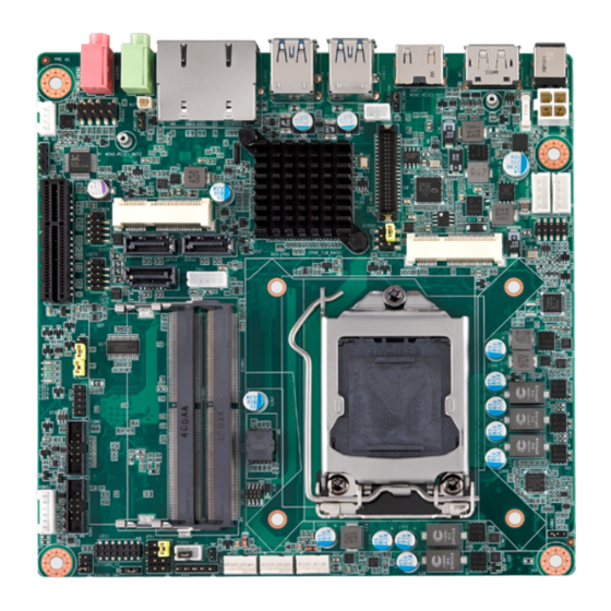
Introduction AIMB-285 is designed with the Intel® H110 for industrial applications that require both performance computing and enhanced power management capabilities. The motherboard supports Intel desktop Core i7/i5/i3/Pentium/Celeron processor up to 8 MB L3 cache and DDR4 SO-DIMM 2133 up to 32GB. A rich I/O connectivity of 2 serial ports, 10 x USB, dual GbE LAN, 3 x SATA ports. -
Page 14: Graphics
Power supply voltage: 12V Input Jumpers and Connectors Connectors on the AIMB-285 motherboard link it to external devices such as hard disk drives and a keyboard. In addition, the board has a number of jumpers used to configure your system for your application. -
Page 15: Table 1.2: Jumper List
COM2 RI# pin RI#/5V/12V Select JCASEOP_SW1 Case open selection pin header JFP2 Power LED and Keyboard Lock Pin Header PSON2 ATX/AT Mode Selection JFP1 Power Switch/HDD LED/SMBUS/Speaker Pin Header JCASE1 Case-Open Detect Connector JLVDS1 LVDS Panel Voltage Selection AIMB-285 User Manual... -
Page 16: Board Layout: Jumper And Connector Locations
Mini PCIE2 VGA1 PCIEx4 Mini PCIE1 SATA2 SATA1 USB56 INV1 JLVDS1 USB78 PCH1 SATA3 JWDT1+JOBS1 DIMMA1 DIMMB1 GPIO1 CPU1 SPI1 COM2 SPI_CN1 COM1 KBMS1 JSETCOM2_V1 PSON2 SYSFAN1 CPUFAN1 LPC1 JFP1 JFP2 SYSFAN2 Figure 1.1 Jumper and Connector Location AIMB-285 User Manual... -
Page 17: Aimb-285 Board Diagram
2 RS-232, (Optional) PS/2, WDT, 8 GPIO Figure 1.2 AIMB-285 Board Diagram Safety Precautions Warning! Always completely disconnect the power cord from chassis whenever you work with the hardware. Do not make connections while the power is on. Sensitive electronic components can be damaged by sudden power surges. -
Page 18: Jumper Settings
1.8.2 CMOS Clear (CMOS1) The AIMB-285 motherboard contains a jumper that can erase CMOS data and reset the system BIOS information. Normally this jumper should be set with pins 1-2 closed. If you want to reset the CMOS data, set J1 to 2-3 closed for just a few sec- onds, and then move the jumper back to 1-2 closed. -
Page 19: Power Led And Keyboard Lock Pin Header (Jfp2)
Watchdog Timer Disable (1-2) OBS BEEP(4-5) (Default) (1 and 2)+(8 and 9) 1.8.6 ATX, AT Mode Selection (PSON2) Table 1.7: PSON2: ATX, AT Mode Selector Closed Pins Result 1-2 AT mode 1-2 closed 2-3* ATX mode 2-3 closed Default AIMB-285 User Manual... -
Page 20: Lvds Panel Voltage Selection (Jlvds1)
5 and 6 System Memory AIMB-285 has two sockets for a 260-pin DDR4 SODIMM. This socket uses a 1.2 V unbuffered double data rate synchronous DRAM (DDR SDRAM). DRAM is available in capacities of 2 GB, 4 GB, 8 GB and 16 GB. The sockets can be filled in any combi- nation with SODIMMs of any size, giving a total memory size between 2 GB, 4 GB, 8 GB, and 16 GB. -
Page 21: Memory Installation Procedures
1.11 Cache Memory The AIMB-285 supports a CPU with one of the following built-in full speed Last Level Cache: 8MB for Intel Core i7-6700 8MB for Intel Core i7-6700TE... -
Page 22: Chapter 2 Connecting Peripherals
Chapter Connecting Peripherals... -
Page 23: Introduction
LAN Ports & USB Ports (LAN1/ LAN12/USB312/ USB334/USB56/USB78) The AIMB-285 provides up to ten USB ports. Four USB3.0 on the rear side and four pin header on the board and other two on Mini PCIE connector. The USB interface complies with USB Specification Rev. 2.0 and Rev. 3.0 supporting transmission rates up to 625 Mbps and is fuse protected. -
Page 24: High Definition Multimedia Interface Connector(Hdmi1)
The AIMB-285 includes HDMI interface that can drive conventional HDMI displays. HDMI1 is a standard 19-pin HDMI connector commonly used for HDMI. Display Port (DP1) The AIMB-285 includes DP interface that can drive conventional DP displays. DP1 is a standard 20-pin DP connector commonly used for DP. AIMB-285 User Manual... -
Page 25: Ps/2 Keyboard And Mouse Connector (Kbms1)
PS/2 Keyboard and Mouse Connector (KBMS1) On board 6-pin wafer box connector, supports one standard PS/2 keyboard, one standard PS/2 mouse. CPU Fan Connector (CPU_FAN1) If a fan is used, this connector supports cooling fans of 500 mA (6 W) or less. AIMB-285 User Manual... -
Page 26: System Fan Connector (Sysfan1)
If a fan is used, this connector supports cooling fans of 500 mA (6 W) or less. Power Switch/HDD LED/SMBUS/Speaker Pin Header (JFP1) & Power LED and Keyboard Lock Pin Header (JFP2) There are several headers for monitoring and controlling the AIMB-285. AIMB-285 User Manual... -
Page 27: Atx Soft Power Switch (Jfp1/Pwr_Sw)
2.8.4 External speaker (JFP1/SPEAKER) JFP1/SPEAKER is a 4-pin connector for an external speaker. If there is no external speaker, the AIMB-285 provides an onboard buzzer as an alternative. To enable the buzzer, set pins 7 & 10 as closed. 2.8.5 Power LED and keyboard lock connector (JFP2/PWR_LED &... -
Page 28: Sata Signal Connector (Sata1 ~ Sata3)
SATA Signal Connector (SATA1 ~ SATA3) AIMB-285 features a high performance Serial ATA III interface (up to 600 MB/s) which eases hard drive cabling with thin, space-saving cables. 2.10 SATA_PWR1/2 AIMB-285 User Manual... -
Page 29: Hd Analog Audio Interface (Audio1,Audio2, Fpaud1)
For motherboards with the optional HD Audio feature, we recommend that you connect a high-definition front panel audio module to this con- nector to take advantage of the motherboard’s high definition audio capability 2.12 PCI-E x4 Slot (PCIEX4_1) AIMB-285 provides 1x PCI express x4 slot. AIMB-285 User Manual... -
Page 30: Lvds Panel Connector (Lvds1), Bom Optional
2.13 LVDS Panel Connector (LVDS1), BOM optional The SPI flash card pin header may be used to flash BIOS if the AIMB-285 cannot power on. 2.14 LVDS Backlight Inverter Power Connector (INV1) Note! Signal Description Signal Signal Description Vadj=0.75 V (Recommended: 4.7 K, 1/16 W) -
Page 31: Minipcie And Msata Connector (Minipcie1)
2.15 MINIPCIE and mSATA Connector (MINIPCIE1) 2.16 MINIPCIE Connector (MINIPCIE2) & SIM Card Socket (SIM1) AIMB-285 User Manual... -
Page 32: Hd Digital Audio Interface (Spdif1)
2.17 HD Digital Audio Interface (SPDIF1) AIMB-285 User Manual... -
Page 33: Audio Amplifier Output Connector (Amp1)
2.18 Audio Amplifier Output Connector (AMP1) 2.19 General purpose I/O Connector (GPIO1) AIMB-285 User Manual... -
Page 34: Spi Bios Flash Socket (Spi1)
2.20 SPI BIOS Flash Socket (SPI1) The SPI flash card pin header may be used to flash BIOS if the AIMB-285 cannot power on. 2.21 SPI Programming Pin Header (SPI_CN1) AIMB-285 User Manual... -
Page 35: Low Pin Count Header (Lpc1)
2.22 Low Pin Count Header (LPC1) 2.23 Case-Open Detect Connector (JCASE1) AIMB-285 User Manual... -
Page 36: Atx 12V Power Supply Connector (Atx12V1) & Atx 5V Power Supply Connector (Atx5Vsb1)
2.24 ATX 12V Power Supply Connector (ATX12V1) & ATX 5V Power Supply Connector (ATX5VSB1) 2.25 Battery Header (BAT1) AIMB-285 User Manual... -
Page 37: Cpu Socket (Cpu1)
2.26 CPU Socket (CPU1) 2.27 DDR4 SO-DIMM Socket (DIMMA1, DIMMB1) AIMB-285 User Manual... -
Page 38: Bios Operation
Chapter BIOS Operation... -
Page 39: Introduction
AIMB-285 setup screens. BIOS Setup The AIMB-285 Series system has AMI BIOS built in, with a CMOS SETUP utility that allows users to configure required settings or to activate certain system features. The CMOS SETUP saves the configuration in the CMOS RAM of the motherboard. -
Page 40: Advanced Bios Features
3.2.2 Advanced BIOS Features Select the Advanced tab from the AIMB-285 setup screen to enter the Advanced BIOS Setup screen. You can select any of the items in the left frame of the screen, such as CPU Configuration, to go to the sub menu for that item. You can display an Advanced BIOS Setup option by highlighting it using the <Arrow>... - Page 41 ACPI Sleep State [ S3 (Suspend to RAM) ] Select ACPI sleep state the system will enter when the SUSPEND button is pressed. Lock Legacy Resources [ Disabled ] S3 Video Repost [ Disabled ] AIMB-285 User Manual...
- Page 42 3.2.2.2 PCH-FW Configuration ME Unconfig on RTC Clear Status [ Enabled ] ME State [ Enabled ] AIMB-285 User Manual...
- Page 43 3.2.2.3 Super IO Configuration AIMB-285 User Manual...
- Page 44 Serial Port 1 Configuration – Serial Port [ Enabled ] – Device Settings IO=3F8h; IRQ = 4 – Change Settings [ Auto ] Serial Port 2 Configuration AIMB-285 User Manual...
- Page 45 – Serial Port [ Enabled ] – Device Settings IO=2F8h; IRQ = 3 – Change Settings [ Auto ] – Device Mode [ RS232 ] Digital I/O Configuration AIMB-285 User Manual...
- Page 46 3.2.2.4 H/W Monitor CPU Warning Temperature [ Disabled ] Use this to set the CPU warning temperature threshold. When the system reaches the warning temperature, the speaker will beep. ACPI Shutdown Temperature [ Disabled ] AIMB-285 User Manual...
- Page 47 ACPI OS to protect the system from overheating damage. Smart Fan Mode Configuration 3.2.2.5 S5 RTC Wake Settings The item allows you enable or disable system wake up on alarm event. AIMB-285 User Manual...
- Page 48 Wake system from S5 [ Disabled ] Enable or disable system wake on alarm event. – Select FixedTime: System will wake on the specific hr:min:sec. 3.2.2.6 Serial Port Console Redirection AIMB-285 User Manual...
- Page 49 Console Redirection [ Disabled ] Enable or disable the console redirection feature 3.2.2.7 CPU Configuration AIMB-285 User Manual...
- Page 50 CPU Configuration The item shows your CPU specification and features (content may be different with different CPUs). AIMB-285 User Manual...
- Page 51 Power Limit 3 Settings – Power Limit 3 Override [ Disabled ] If this option is enabled, BIOS will leave the default values for Power Limit 3 and Power Limit 3 Power Window. Power Limit 4 Settings AIMB-285 User Manual...
- Page 52 Enable: ACPI thermal management use DTS SMM mechanism to obtain CPU temperature values. Out of Spec: ACPI thermal management use EC reported temperature val- ues and DTS SMM mechanism is used to handle Out of Spec. – ACPI 3.0 T-States [ Disabled ] AIMB-285 User Manual...
- Page 53 3.2.2.8 Intel TXT Information AIMB-285 User Manual...
- Page 54 Native PCIE Enable [ Enabled ] Note! PCI Express Native support is only available in Vista. Native ASPM [ Auto ] BOAT ACPI Table Support [ Disabled ] PCI Delay Optimization [ Disabled ] AIMB-285 User Manual...
- Page 55 SATA Configuration SATA Controllers [ Enabled ] SATA Mode Selection [ AHCI ] Aggressive LPM Support [ Enabled ] Serial ATA Port 1 [ Enabled ] Serial ATA Port 2 [ Enabled ] AIMB-285 User Manual...
- Page 56 Serial ATA Port 3 [ Enabled ] mSATA [ Enabled ] 3.2.2.11 Network Stack Configuration AIMB-285 User Manual...
- Page 57 Network Stack [ Disabled ] Enable / Disable UEFI Network Stack 3.2.2.12 CSM Configuration AIMB-285 User Manual...
- Page 58 2. Change all of the settings above as " Legacy" - Boot option filter -> Legacy Only - Network -> Legacy - Storage -> Legacy - Video -> Legacy - Other PCI devices -> Legacy AIMB-285 User Manual...
- Page 59 3.2.2.13 NVMe Configuration AIMB-285 User Manual...
- Page 60 3.2.2.14 USB Configuration AIMB-285 User Manual...
-
Page 61: Chipset Configuration Setting
Users can display a Chipset Setup option by highlighting it using the <Arrow> keys. All Chipset Setup options are described in this section. The Chipset Setup screens are shown below. The sub menus are described on the following pages. AIMB-285 User Manual... - Page 62 3.2.3.1 System Agent (SA) Configuration VT-d [ Enabled ] Disable or enable VT-d capability. Above 4GB MMIO BIOS assignment [ Disabled ] Graphics Configuration AIMB-285 User Manual...
- Page 63 – PM Support [ Enabled ] – PAVP Enable [ Enabled ] – Cdynmax Clamping Enable [ Enabled ] – Cd Clock Frequency [ 675 Mhz ] LCD Control – LVDS Panel Type [ Disabled ] AIMB-285 User Manual...
- Page 64 DMI/ OPI Configuration – DMI Max Link Speed [ Auto ] Set DMI Speed at Gen1/ Gen2/ Gen3. Gen3 Root Port Press Value for each Lane AIMB-285 User Manual...
- Page 65 Gen3 Endpoint Preset value for each Lane Gen3 Endpoint Hint value for each Lane AIMB-285 User Manual...
- Page 66 Gen 3 RxCLTE Control PEG Port Configuration AIMB-285 User Manual...
- Page 67 Program PCIe ASPM after OpROM [ Disabled ] Enabled: PCIe ASPM will be programmed after OpROM. Disabled: PCIe ASPM will be programmed before OpROM. – Program Static Phase1 Eq [ Enabled ] – PEG Sampler Calibrate [ Disabled ] AIMB-285 User Manual...
- Page 68 Gen3 Root Port Preset value for each Lane Gen3 Endpoint Preset value for each Lane AIMB-285 User Manual...
- Page 69 Gen3 Endpoint Hint value for each Lane Gen3 RxCTLE Control – RxCTLE Override [ Disabled ] AIMB-285 User Manual...
- Page 70 Maximum Value of TOLUD. Dynamic assignment would adjust TOLUD automatically based on largest MMIO length of installed graphic controller. – Retrain on Fast Fail [ Enabled ] – Memory Remap [ Enabled ] – Fast Boot [ Enabled ] AIMB-285 User Manual...
- Page 71 GT- Power Management Control – RC6 (Render Standby) [ Enabled ] Check to enable / disable render standby supported. 3.2.3.2 PCH-IO Configuration AIMB-285 User Manual...
- Page 72 PCIE Wake [ Disabled ] Enable or disable PCIE Wake feature. Deep Sleep [ Disabled ] Enable or disable the Deep Sleep function. High Precision Timer [ Enbled ] Start After G3 [ Power Off ] AIMB-285 User Manual...
- Page 73 DMI Link ASPM Control [ Enabled ] Enable or disable the control of Active State Power Management on SA side of the DMI Link. – Peer Memory Write Enable [ Disabled ] – PCIe-USB Glitch W/A [ Disabled ] AIMB-285 User Manual...
- Page 74 PCI Express G3 Eq Lanes – Override SW EQ settings [ Disabled ] Mini PCI Express1 – Mini PCI Express [ Enabled ] Enable or disable PCI Express Root Port controller. – ASPM Support [ Auto ] AIMB-285 User Manual...
- Page 75 Mini PCI Express2 – Mini PCI Express [ Enabled ] Enable or disable PCI Express Root Port controller. – ASPM Support [ Auto ] – L1 Substates [ L1.1 & L1.2 ] – PCIe Speed [ Auto ] AIMB-285 User Manual...
- Page 76 USB Configuration – USB Pre-condition [ Disabled ] Note! USB 2.0 & 3.0 only supported from 1 XHCI controller. AIMB-285 User Manual...
- Page 77 BIOS Security Configuration – RTC Lock [ Enabled ] Enable will lock bytes 38h-3Fh in the lower/upper 128 byte bank of RTC RAM. – BIOS Lock [ Enabled ] HD Audio Configuration AIMB-285 User Manual...
-
Page 78: Security Setting
This item is to control detection of the HD-Audio device. [ Disabled ] = HAD will be unconditionally disabled. [ Enabled ] = HAD will be unconditionally enabled. [ Auto ] = HAD will be enabled if present, disabled otherwise. 3.2.4 Security Setting AIMB-285 User Manual... - Page 79 Secure Boot [ Disabled ] Secure Boot can be enabled if 2 conditions below: 1. System is running in user mode with enrolled Platform Key (PK) 2. CSM function is disabled Secure Boot Mode [ Custom ] AIMB-285 User Manual...
-
Page 80: Boot Setting
3.2.4.2 Key Management Provision Factory Default Keys [ Disabled ] Install factory default Secure Boot Keys when system is in setup mode. 3.2.5 Boot Setting Setup Prompt Timeout [ 1 ] AIMB-285 User Manual... -
Page 81: Save & Exit Configuration
1. Select Exit Discarding Changes from the Exit menu and press <Enter>. The following message appears: Discard Changes and Exit Setup Now? [Ok] or [Cancel] 2. Select Ok to discard changes and exit. Discard Changes Select Discard Changes from the Exit menu and press <Enter>. AIMB-285 User Manual... - Page 82 <Enter>. Save as User Default Save the all current settings as a user default. Restore User Default Restore all settings to user default values. Boot Override Shows the boot device types on the system. AIMB-285 User Manual...
- Page 83 AIMB-285 User Manual...
-
Page 84: Software Introduction & Service
Chapter Software Introduction & Service... -
Page 85: Introduction
Introduction The mission of Advantech Embedded Software Services is to "Enhance quality of life with Advantech platforms and Microsoft® Windows® embedded technology." We enable Windows® Embedded software products on Advantech platforms to more effectively support the embedded computing community. Customers are freed from the hassle of dealing with multiple vendors (hardware suppliers, system integrators, embedded OS distributors) for projects. - Page 86 System Throttling Refers to a series of methods for reducing power consump- tion in computers by lowering the clock frequency. This API allows the user to adjust the clock from 87.5% to 12.5%. AIMB-285 User Manual...
-
Page 87: Software Utility
The eSOS also provide for remote connection via Telnet server and FTP server so the administrator can attempt to rescue the system. Note: This function requires BIOS cus- tomization. AIMB-285 User Manual... -
Page 88: Chipset Software Installation Utility
Chapter Chipset Software Installation Utility... -
Page 89: Before You Begin
Before You Begin To facilitate the installation of the enhanced display drivers and utility software, read the instructions in this chapter carefully. The drivers for the AIMB-285 are located on Advantech support website: http://support.advantech.com/support/. The driver on the support website will guide and link you to the utilities and drivers under a Windows system. -
Page 90: Graphic Setup
Chapter Graphic Setup... -
Page 91: Introduction
For Win8 OS, its inbox driver can enable USB controller and work automatically. You still can download and update WIN8.1 USB 3.0 driver from website. Here you can download USB 3.0 driver for installation: http://support.advantech.com/ Support/ Windows 7/8 driver installation... -
Page 92: Lan Configuration
Chapter LAN Configuration... -
Page 93: Introduction
Introduction The AIMB-285 has dual Gigabit Ethernet LANs via dedicated PCI Express x1 lanes Realtek 8111G (LAN1 & LAN2) that offer bandwidth of up to 500 MB/sec, eliminating the bottleneck of network data flows and incorporating Gigabit Ethernet at 1000 Mbps. - Page 94 AIMB-285 User Manual...
- Page 95 AIMB-285 User Manual...
-
Page 96: Appendix A I/O Pin Assignments
Appendix I/O Pin Assignments... -
Page 97: Dc Input Phoenix Connector
DC input Phoenix Connector Signal Signal VCC(12V) Display Port Signal Signal DP1_0+ DP1_3- DP1_0- DP1_AUX_EN# DP1_1+ DP1_AUX+ DP1_1- DP1_2+ DP1_AUX- DP1_HPD DP1_2- DP1_3+ +V3.3_DP1 AIMB-285 User Manual... -
Page 98: High Definition Multimedia Interface
High Definition Multimedia Interface Signal Signal HDMI1_Z_D2+ HDMI1_Z_CLK- HDMI1_Z_D2- HDMI1_Z_D1+ HDMI1_SCL HDMI1_Z_D1- HDMI1_SDA HDMI1_Z_D0+ +V5_HDMI HDMI1_Z_D0- HDMI1_HPD HDMI1_Z_CLK+ ATX Power supply (5VSB) connector Signal +V5SB PS_ON# AIMB-285 User Manual... -
Page 99: Usb 3.0 Stack Connector
TX0- TX1- TX0+ TX1+ RJ45 2 Port Signal Signal MDI_LAN1_DP0 LAN2_MDI0+ MDI_LAN1_DN0 LAN2_MDI0- MDI_LAN1_DP1 LAN2_MDI1+ MDI_LAN1_DN1 LAN2_MDI1- LAN1_CONN LAN2_CONNved LAN1_CT LAN2_CT MDI_LAN1_DP2 LAN2_MDI2+ MDI_LAN1_DN2 LAN2_MDI2- MDI_LAN1_DP3 LAN2_MDI3+ MDI_LAN1_DN3 LAN2_MDI3- LAN1_LED0_ACT# LAN2_LED1_ACT# +V3.3_DUAL +V3.3_DUAL LAN1_LED1_1G# LAN2_LED2_1G# LAN1_LED2_100M# LAN2_LED0_100M# AIMB-285 User Manual... -
Page 100: Battery Wafer Box
Battery Wafer Box Signal VBAT HD Analog Audio Interface AUDIO1: LINE-OUT AUDIO2: MIC Front HD Analog Audio Interface Signal Signal MIC IN L MIC IN R FPAUD_DETECT# LINE OUT R SENSE R1 SENSE LINE OUT L SENSE R2 AIMB-285 User Manual... -
Page 101: Audio Amplifier Output Connector
A.10 Audio Amplifier Output Connector Signal A.11 HD Digital Audio Interface Signal SPDIF OUT A.12 PCI-E x4 Slot Signal Signal +12V PRSNT1# +12V +12V +12V +12V SMB_CLK Reserved SMB_DATA Reserved Reserved Reserved +3.3V Reserved +3.3V +3.3VAUX +3.3V AIMB-285 User Manual... -
Page 102: Minipcie And 3G Connector
TX2- RX2+ RX2- TX3+ TX3- RX3+ Reserved RX3- Reserved CONFIG2 A.13 MINIPCIE and 3G Connector Signal Signal WAKE# +3.3Vaux Reserved Reserved +1.5V CLKREQ# UIM_PWR UIM_DATA REFCLK- UIM_CLK REFCLK+ UIM_RESET UIM_VPP Reserved Reserved DISABLE# DETECT# RESET# PCIE_RX+ +3.3Vaux AIMB-285 User Manual... -
Page 103: Usb 2.0 Connector
PCIE_RX- +1.5V SMB_CLK PCIE_TX- SMB_DATA PCIE_TX+ USB_D- USB_D+ +3.3Vaux +3.3Vaux Reserved V1.2_DETECT# LED_WLAN# Reserved Reserved Reserved +1.5V Reserved Reserved +3.3Vaux A.14 USB 2.0 Connector Signal Signal AIMB-285 User Manual... -
Page 104: Sata Signal Connector
A.15 SATA Signal Connector Signal A.16 LVDS Backlight Inverter Power Connector Signal +12V BKL_EN BKL_CTRL A.17 General Purpose I/O Pin Header Signal Signal GPIO0 GPIO4 GPIO1 GPIO5 GPIO2 GPIO6 GPIO3 GPIO7 +3.3V AIMB-285 User Manual... -
Page 105: Com Port
COM Port Signal Signal DSR# RTS# CTS# A.19 PS/2 Keyboard and Mouse Connector Signal Signal KB CLK KB DATA MS CLK MS DATA A.20 Low Pin Count Header Signal Signal CLK_33M RESET# FRAME# +3.3V SMB_CLK SERIRQ SMB_DATA +5VSB AIMB-285 User Manual... -
Page 106: System Fan Power Connector
A.21 SYSTEM FAN Power Connector Signal +12V DETECT PWM IN A.22 SPI Programming Pin Header Signal Signal +3.3V MISO MOSI A.23 SPI BIOS Flash Socket Signal Signal MOSI MISO WP# / IO2 HOLD# / IO3 +3.3V AIMB-285 User Manual... -
Page 107: Cpu Fan Power Connector
CPU FAN Power Connector Signal +12V DETECT PWM IN A.25 SMBUS Programming INFINEON for +Vcore Controller Signal INF_SMBCLK INF_SMBDATA A.26 MINIPCIE and mSATA Connector MINIPCIE: Signal Signal WAKE# +3.3Vaux Reserved Reserved +1.5V CLKREQ# Reserved Reserved REFCLK- Reserved REFCLK+ Reserved Reserved AIMB-285 User Manual... - Page 108 Signal Reserved +3.3V Reserved Reserved +1.5V Reserved Reserved Reserved Reserved Reserved Reserved Reserved Reserved Reserved Reserved Reserved DETECT# Reserved +3.3V +1.5V SMB_CLK SMB_DATA Reserved Reserved +3.3V +3.3V Reserved Reserved Reserved Reserved Reserved Reserved +1.5V Reserved MSATA_DETECT# +3.3V AIMB-285 User Manual...
-
Page 109: Video Graphics Array Connector
A.27 Video Graphics Array Connector Signal Signal GREEN BLUE VSYNC HSYNC A.28 SATA Power Connector Signal Signal +V12 AIMB-285 User Manual... -
Page 110: Lvds Panel Connector
OD0- ED0- OD0+ ED0+ OD1- ED1- OD1+ ED1+ OD2- ED2- OD2+ ED2+ OCK- ECK- OCK+ ECK+ DDC_CLK DDC_DAT OD3- ED3- OD3+ ED3+ LVDS_ENBKL VCON Please connect Pin3 to any GND pin on LVDS panel to enable LVDS. AIMB-285 User Manual... -
Page 111: Atx 12V Power Supply Connector
A.30 ATX 12V Power Supply Connector Signal +12V +12V A.31 SIM Card Connector Signal UIM_PWR UIM_RESET UIM_CLK Reserved UIM_VPP UIM_DATA Reserved AIMB-285 User Manual... - Page 112 AIMB-285 User Manual...
- Page 113 No part of this publication may be reproduced in any form or by any means, electronic, photocopying, recording or otherwise, without prior written permis- sion of the publisher. All brand and product names are trademarks or registered trademarks of their respective companies. © Advantech Co., Ltd. 2016...
- Page 114 Our company network supports you worldwide with offices in Germany, Great Britain, Turkey and the USA. For more information please contact: Distec GmbH FORTEC Elektronik AG Augsburger Str. 2b Lechwiesenstr. 9 82110 Germering 86899 Landsberg am Lech Germany Germany Phone: +49 (0)89 / 89 43 63-0 Phone: +49 (0)8191 / 911 72-0...
Need help?
Do you have a question about the AIMB-285 and is the answer not in the manual?
Questions and answers