
Related Manuals for Advantech AIMB-212


Summary of Contents for Advantech AIMB-212
- Page 1 User Manual AIMB-212 Intel® Atom N450/D510 1.6 GHz Mini-ITX with VGA/LVDS, 6 COM, Dual GbE LAN, 8 USB, Mini PCIe...
- Page 2 No part of this manual may be reproduced, copied, translated or transmitted in any form or by any means without the prior written permission of Advantech Co., Ltd. Information provided in this manual is intended to be accurate and reliable. How- ever, Advantech Co., Ltd.
- Page 3 Whether your new Advantech equipment is destined for the labo- ratory or the factory floor, you can be assured that your product will provide the reliability and ease of operation for which the name Advantech has come to be known.
-
Page 4: Declaration Of Conformity
Caution! There is a danger of a new battery exploding if it is incorrectly installed. Do not attempt to recharge, force open, or heat the battery. Replace the battery only with the same or equivalent type recommended by the man- ufacturer. Discard used batteries according to the manufacturer's instructions. AIMB-212 User Manual... - Page 5 M470T2864AZ3 HCE6 (64X16) -CE6 DDR2 ELPIDA E1116AESE-6E-F (64x16) DDR2 ELPIDA E5108AGBG-6E- E (64x8) DDR2 ELPIDA E1108ACSE-6E- E (128x8) DDR2 TS128MSQ64V HYNIX HY5PS12821E- FP-S5 (64x8) Transcend DDR2 TS64MSQ64V6 Hynix HY5PS121621B (RoHS) FP-Y5 (32x16) DDR2 TS256MSQ64V Micron D9HNP (128x8) AIMB-212 User Manual...
-
Page 6: Ordering Information
Because of Advantech’s high quality-control standards and rigorous testing, most of our customers never need to use our repair service. If an Advantech product is defec- tive, it will be repaired or replaced at no charge during the warranty period. For out- of-warranty repairs, you will be billed according to the cost of replacement materials, service time and freight. - Page 7 It should be free of marks and scratches and in perfect working order upon receipt. As you unpack the AIMB-212, check it for signs of ship- ping damage. (For example, damaged box, scratches, dents, etc.) If it is damaged or it fails to meet the specifications, notify our service department or your local sales representative immediately.
- Page 8 AIMB-212 User Manual viii...
-
Page 9: Table Of Contents
Board layout: Jumper and Connector Locations ........6 Figure 1.1 Jumper and Connector Location ........ 6 Figure 1.2 I/O Connectors ............6 AIMB-212 Board Diagram ................. 7 Figure 1.3 AIMB-212 Board Diagram .......... 7 Safety Precautions ..................8 Jumper Settings ..................9 1.8.1 How to Set Jumpers.............. - Page 10 4.2.2 Software Utility................56 Chapter Chipset Software Installation Utility Before You Begin..................58 Introduction ..................... 58 Windows XP Driver Setup............... 59 Chapter VGA Setup ......... 61 Introduction ..................... 62 Windows 7/Vista/XP................62 Chapter LAN Configuration ......63 AIMB-212 User Manual...
- Page 11 Table B.18:LVDS Power Jumper ..........83 B.19 LVDS Inverter (VP1) ................83 Table B.19:LVDS Power Jumper ..........83 B.20 DMA Channel Assignments ..............84 Table B.20:DMA Channel Assignments........84 B.21 Interrupt Assignments ................84 Table B.21:Interrupt Assignments..........84 AIMB-212 User Manual...
- Page 12 B.22 1st MB Memory Map................84 Table B.22:1st MB Memory Map ..........84 AIMB-212 User Manual...
-
Page 13: Chapter 1 General Information
Chapter General Information... -
Page 14: Introduction
Introduction The AIMB-212 is designed with the Intel® Atom N450/D510 and the ICH8M for industrial applications that require both performance computing and enhanced power management capabilities. The motherboard has on board CPU Intel® Atom™ N450/ D510 1.66 GHz and DDR2 667 MHz up to 2 GB. -
Page 15: Specifications
500 MB/s data transmission rate Controller: LAN1: Intel 82567v; LAN2: Intel 82583v 1.3.6 Industrial features Watchdog timer: Can generate a system reset. The watchdog timer is pro- grammable, with each unit equal to one second or one minute (255 levels) AIMB-212 User Manual... -
Page 16: Mechanical And Environmental Specifications
Board weight: 0.365 kg Jumpers and Connectors Connectors on the AIMB-212 motherboard link it to external devices such as hard disk drives and a keyboard. In addition, the board has a number of jumpers used to configure your system for your application. - Page 17 SATA2 Serial ATA data connector 2 SATA_PWR_CN1 Serial ATA power connector 1 SATA_PWR_CN2 Serial ATA power connector 2 DIMMA1 Memory connector channel. SPI_CN1 SPI flash update connector. MINIPCIE2 Mini PCI express connector ATX12V ATX 12 V connector AIMB-212 User Manual...
-
Page 18: Board Layout: Jumper And Connector Locations
1 4 7 10 JWDT1 1 2 3 4 5 JFP1 PCI1 CPUFAN1 DIMM1 SYSFAN1 COM4 COM5 COM6 USB56 GPIO1 MINIPCIE2 SATA1 SATA2 CMOS1 KBMS1 USB78 SATA_PWR_CN1 SATA_PWR_CN2 Figure 1.1 Jumper and Connector Location Figure 1.2 I/O Connectors AIMB-212 User Manual... -
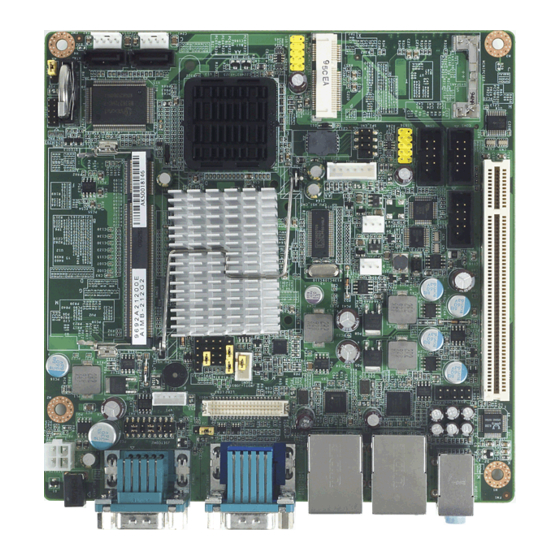
Page 19: Aimb-212 Board Diagram
2 SATA ports 300 MB/s PCIe x1 Intel 82583V ICH8M 8 USB Ports 32-bit/33MHz PCI Bus Realtek ALC888 Mini-PCIe PCIe x1 HD Audio Super IO Winbond Fintek 8-bit GPIO W83627DHG F81216D 4 RS-232 Figure 1.3 AIMB-212 Board Diagram AIMB-212 User Manual... -
Page 20: Safety Precautions
Caution! There is a danger of a new battery exploding if it is incorrectly installed. Do not attempt to recharge, force open, or heat the battery. Replace the battery only with the same or equivalent type recommended by the man- ufacturer. Discard used batteries according to the manufacturer’s instructions. AIMB-212 User Manual... -
Page 21: Jumper Settings
1.8.2 CMOS Clear (CMOS1) The AIMB-212 motherboard contains a jumper that can erase CMOS data and reset the system BIOS information. Normally this jumper should be set with pins 1-2 closed. If you want to reset the CMOS data, set J1 to 2-3 closed for just a few sec- onds, and then move the jumper back to 1-2 closed. -
Page 22: Com2 Rs 232/422/485 Mode Selector (Jsetcom2)
(1-2) + (9-11) + (10-12) + (15-17) + (16-18) closed *: Default 1.8.4 J1: LCD Power 3.3 V/5 V Selector Table 1.5: J1: LCD Power 3.3 V/5 V Selector Closed Pins Result 1-2* 3.3 V* Default 3.3 V 2-3 closed 1-2 closed AIMB-212 User Manual... -
Page 23: Pson1: Atx, At Mode Selector
ATX Mode Default ATX Mode AT Mode 2-3 closed 1-2 closed 1.8.6 JWDT1: Watchdog Timer Output Option Table 1.7: JWDT1: Watchdog Timer Output Option Closed Pins Result 2-3* System Reset* Default System Reset 2-3 closed 1-2 closed AIMB-212 User Manual... -
Page 24: System Memory
SDRAM). They are available in capacities of 256, 512, and 1024 MB. The sockets can be filled in any combination with DIMMs of any size, giving a total memory size between 256 MB and 2 GB. AIMB-212 does NOT support ECC (error checking and correction). -
Page 25: Chapter 2 Connecting Peripherals
Chapter Connecting Peripherals... -
Page 26: Introduction
USB Ports (LAN1_USB12/LAN2_USB34/USB56/ USB78) The AIMB-212 provides up to eight ports of USB (Universal Serial Bus). The USB interface complies with USB Specification Rev. 2.0 supporting transmission rate up to 480 Mbps and is fuse protected. The USB interface can be disabled in the system BIOS setup. -
Page 27: Vga Connector (Vga1)
VGA Connector (VGA1) The AIMB-212 includes a VGA interface that can drive conventional CRT displays. VGA1 is a standard 15-pin D-SUB connector commonly used for VGA. Pin assign- ments for CRT connector VGA1 are detailed in Appendix B. AIMB-212 User Manual... -
Page 28: Serial Ports (Com1~Com6)
Serial Ports (COM1~COM6) COM1/COM2/COM3 AIMB-212 supports six serial ports. 1 of RS-232/422/485 - COM1, COM2, COM3, COM4, COM5 and COM6. The user can use JSETCOM2 to select among RS 232/ 422/485 modes for COM2. These ports can connect to serial devices, such as a mouse or a printer, or to a communications network. -
Page 29: Ps/2 Keyboard And Mouse Connector (Kbms1)
PS/2 Keyboard and Mouse Connector (KBMS1) On board 6pin wafer box connector, supports one standard PS/2 keyboard, one stan- dard PS/2 mouse. AIMB-212 User Manual... -
Page 30: Cpu Fan Connector (Cpu_Fan1)
CPU Fan Connector (CPU_FAN1) If fan is used, this connector supports cooling fans of 500 mA (6 W) or less. AIMB-212 User Manual... -
Page 31: System Fan Connector (Sysfan1)
System FAN Connector (SYSFAN1) COM4/COM5/COM6 If fan is used, this connector supports cooling fans of 500 mA (6 W) or less. AIMB-212 User Manual... -
Page 32: Front Panel Connectors (Jfp1/Jfp1+Jfp2)
External speaker (JFP1+JFP2/ SPEAKER) ((JFP1+JFP2/ SPEAKER)) is a 4-pin connector for an external speaker. If there is no external speaker, the AIMB-212 provides an onboard buzzer as an alternative. To enable the buzzer, set pins 3-4 as closed. AIMB-212 User Manual... -
Page 33: Power Led And Keyboard Lock Connector
PSON1 Connect 1-2 pin cable (On Back plane) 2-3 pin closed 1-2 pin closed with switch Jumper setting System On System Suspend Fast flashes Fast flashes Fast flashes System Off Slow flashes AIMB-212 User Manual... -
Page 34: Line In, Line Out, Mic In Connector (Audio1)
Line In, Line Out, Mic In Connector (AUDIO1) Line In Line Out Mic In AIMB-212 User Manual... -
Page 35: Serial Ata Interface (Sata1, Sata2)
2.10 Serial ATA Interface (SATA1, SATA2) AIMB-212 features a high performance serial ATA interface (up to 300 MB/s) which eases cabling to hard drives with thin and long cables. AIMB-212 User Manual... -
Page 36: Pci
2.11 The AIMB-212 provides 1 x PCI slot. AIMB-212 User Manual... -
Page 37: Front Headphone Connector (Hd1)
I/O module cable to this connector. Note! For motherboards with the optional HD Audio feature, we recommend that you connect a high-definition front panel audio module to this con- nector to avail of the motherboard’s high definition audio capability. AIMB-212 User Manual... -
Page 38: Atx 12V Power Connector (Atx12V)
This connector is for an ATX Micro-Fit power supply. The plugs from the power sup- ply are designed to fit these connectors in only one orientation. Find the proper orien- tation and push down firmly until the connectors completely fit. AIMB-212 User Manual... -
Page 39: Spi Flash Connector(Spi_Cn1)
2.14 SPI Flash connector(SPI_CN1) SPI flash card pin header may be used to flash BIOS if AIMB-212 cannot power on. AIMB-212 User Manual... -
Page 40: Lcd Inverter Connector (Vp1)
2.15 LCD Inverter Connector (VP1) Note! Signal Description Signal Signal Description Vadj=0.75 V (Recommended: 4.7 KΩ, >1/16 W) ENBKL LCD backlight ON/OFF control signal AIMB-212 User Manual... -
Page 41: Lvds Connector (Lvds1)
2.16 LVDS Connector (LVDS1) 2.17 General purpose I/O Connector (GPIO1) AIMB-212 User Manual... - Page 42 AIMB-212 User Manual...
-
Page 43: Bios Operation
Chapter BIOS Operation... -
Page 44: Introduction
This chapter describes the basic navigation of the AIMB-212 setup screens. BIOS Setup The AIMB-212 Series system has build-in AMI BIOS with a CMOS SETUP utility which allows users to configure required settings or to activate certain system fea- tures. -
Page 45: Main Menu
System Date using the <Arrow> keys. Enter new values through the keyboard. Press the <Tab> key or the <Arrow> keys to move between fields. The date must be entered in MM/DD/YY format. The time must be entered in HH:MM:SS format. AIMB-212 User Manual... -
Page 46: Advanced Bios Features
3.2.2 Advanced BIOS Features Select the Advanced tab from the AIMB-212 setup screen to enter the Advanced BIOS Setup screen. You can select any of the items in the left frame of the screen, such as CPU Configuration, to go to the sub menu for that item. You can display an Advanced BIOS Setup option by highlighting it using the <Arrow>... -
Page 47: Cpu Configuration
CPU speed is controlled by the operating system. Intel® C-STATE tech This item allows the CPU to save more power under idle mode. Enhanced C-States CPU idle set to enhanced C-States, disabled by Intel? C-STATE tech item. AIMB-212 User Manual... -
Page 48: Ide Configuration
While entering setup, BIOS auto detects the pres- ence of AHCI devices. This displays the status of auto detection of AHCI devices. Super I/O Configuration This item enables users to set the Super IO device status, including enabling of COM. AIMB-212 User Manual... - Page 49 This item allows user to adjust serial port 4 of address and IRQ. Onboard Serial port 5 [C90/IRQ11] This item allows user to adjust serial port 4 of address and IRQ. Onboard Serial port 6 [C98/IRQ10] This item allows user to adjust serial port 4 of address and IRQ. AIMB-212 User Manual...
-
Page 50: Hardware Health Configuration
ACPI Shut Down Temperature This potion allows user to set the CPU temperature at that the system will auto- matically shut down for preventing CPU from over heat damage. AIMB-212 User Manual... -
Page 51: Acpi Setting
3.2.6 ACPI Setting 3.2.7 General ACPI Configuration Suspend mode Select the ACPI state used for system suspend. Report Video on S3 Resume This item allows you to invoke VA BIOS POST on S3/STR resume. AIMB-212 User Manual... -
Page 52: Advanced Acpi Configuration
This item allows you to enable RSDP pointers to 64-bit fixed system description tables. ACPI APIC support Include APIC table pointer to RSDT pointer list. AMI OEMB table Include OEMB table pointer to R(x)SDT pointer lists. Headless mode Enable / Disable Headless operation mode through ACPI. AIMB-212 User Manual... -
Page 53: Chipset Acpi Configuration
Allows you to configure Intel’s Energy Lake power management technology. APIC ACPI SCI IRQ Enable/Disable APIC ACPI SCI IRQ. USB Device Wakeup From S3/S4 Enable/Disable USB Device Wakeup from S3/S4. High Performance Event Timer Enable/Disable High performance Event timer. AIMB-212 User Manual... -
Page 54: Apm Configuration
This option allows user to set system action when AC power restores after AC power loss. Available options include Power Off, Power On, Last Status. Resume On Ring Disable/Enable RI wake event. Resume On RTC Alarm Disable/Enable RTC wake event. AIMB-212 User Manual... -
Page 55: Usb Configuration
EHCI driver. Hotplug USB FDD Support A dummy FDD device is created that will be associated with the hotplugged FDD later. Auto option creates this dummy device only if there is no USB FDD present. AIMB-212 User Manual... -
Page 56: Usb Mass Storage Device Configuration
3.2.13 Advanced PCI/PnP Settings Select the PCI/PnP tab from the AIMB-212 setup screen to enter the Plug and Play BIOS Setup screen. You can display a Plug and Play BIOS Setup option by highlight- ing it using the <Arrow> keys. All Plug and Play BIOS Setup options are described in this section. -
Page 57: Boot Settings
When set to Reserved will specified DMA will Reserved for use by leg- acy ISA devices. Reserved Memory Size This item allows you to reserved size of memory block for legacy ISA device. 3.2.14 Boot Settings AIMB-212 User Manual... -
Page 58: Boot Settings Configuration
Wait for the F1 key to be pressed if an error occurs. Hit .DEL. Message Display Displays .Press DEL to run Setup. in POST. Interrupt 19 Capture This item allows option ROMs to trap interrupt 19. Bootsafe Function This item allows you to enables or disables bootsafe function. AIMB-212 User Manual... -
Page 59: Security Setup
Change Supervisor / User Password Provides for either installing or changing the password. Boot sector Virus protection The boot sector virus protection will warn if any program tries to write to the boot sector. 3.2.17 Advanced Chipset Settings AIMB-212 User Manual... -
Page 60: North Bridge Chipset Configuration
This item allows you to enables or disables detect by DRAM SPD. Initiate Graphic Adapter This item allows you to select which graphics controller to use as the primary boot device. Internal Graphics Mode Select Select the amount of system memory used by the Internal graphics device. AIMB-212 User Manual... -
Page 61: Video Function Configuration
Boot Display Device Select boot display device at post stage. Flat Panel Type This item allows you to select which panel resolution you wants. Spread Spectrum Clock This item allows you to enables or disables spread spectrum clock. AIMB-212 User Manual... -
Page 62: South Bridge Chipset Configuration
Enables or disables GbE LAN wake up from S5 function. HDA Controller Enables or disables the HDA controller. SMBUS Controller Enables or disables the SMBUS controller. SLP_S4# Min. Assertion Width This item allows you to set a delay of sorts. AIMB-212 User Manual... -
Page 63: Exit Option
Select this option to quit Setup without making any permanent changes to the system configuration. Select Discard Changes and Exit from the Exit menu and press <Enter>. The following message appears: Discard Changes and Exit Setup Now? [Ok] [Cancel] Select Ok to discard changes and exit. AIMB-212 User Manual... - Page 64 Select Discard Changes from the Exit menu and press <Enter>. Load Optimal Defaults The AIMB-212 automatically configures all setup items to optimal settings when you select this option. Optimal Defaults are designed for maximum system per- formance, but may not work best for all computer applications. In particular, do not use the Optimal.
-
Page 65: Software Introduction & Service
Chapter Software Introduction & Service... -
Page 66: Introduction
Introduction The mission of Advantech Embedded Software Services is to "Enhance quality of life with Advantech platforms and Microsoft Windows® embedded technology." We enable Windows® Embedded software products on Advantech platforms to more effectively support the embedded computing community. Customers are freed from the hassle of dealing with multiple vendors (hardware suppliers, system integrators, embedded OS distributors) for projects. - Page 67 Speed depend on the system loading. System Throttling Refers to a series of methods for reducing power consump- tion in computers by lowering the clock frequency. These API allow user to lower the clock from 87.5% to 12.5%. AIMB-212 User Manual...
-
Page 68: Software Utility
OS crash. It will diagnose the hardware sta- tus, and then send an e-mail to administrator. The eSOS also provide Remote Connection: Telnet server and FTP server for administrator to rescue the system. Note: This function requires BIOS customization. AIMB-212 User Manual... -
Page 69: Chipset Software Installation Utility
Chapter Chipset Software Installation Utility... -
Page 70: Before You Begin
To facilitate the installation of the enhanced display drivers and utility software, read the instructions in this chapter carefully. The drivers for the AIMB-212 are located on the software installation CD. The driver in the folder of the driver CD will guide and link you to the utilities and drivers under a Windows system. -
Page 71: Windows Xp Driver Setup
Windows XP Driver Setup Insert the driver CD into your system's CD-ROM drive. You can see the driver folder items. Navigate to the "Chipset" folder and click "infinst_autol.exe" to complete the installation of the driver. AIMB-212 User Manual... - Page 72 AIMB-212 User Manual...
-
Page 73: Vga Setup
Chapter VGA Setup... -
Page 74: Introduction
Insert the driver CD into your system's CD-ROM drive. You can see the driver folders items. Navigate to the "VGA" folder and click "setup.exe" to complete the installation of the drivers for Windows 7, Windows Vista, Windows XP. AIMB-212 User Manual... -
Page 75: Lan Configuration
Chapter LAN Configuration... -
Page 76: Introduction
Introduction The AIMB-212 has dual Gigabit Ethernet LANs via dedicated PCI Express x1 lanes (Intel 82567V (LAN1) and 82583V (LAN2)) that offer bandwidth of up to 500 MB/sec, eliminating the bottleneck of network data flow and incorporating Gigabit Ethernet at 1000 Mbps. -
Page 77: Windows 7/Vista/Xp Driver Setup(Intel 82567V/82583V)
Windows 7/Vista/XP Driver Setup(Intel 82567v/ 82583v) Insert the driver CD into your system's CD-ROM drive. Select the LAN folder then navigate to the directory for your OS. AIMB-212 User Manual... - Page 78 AIMB-212 User Manual...
- Page 79 Appendix Programming the Watchdog Timer...
-
Page 80: Appendix A Programming The Watchdog Timer
Programming the Watchdog Timer The AIMB-212's watchdog timer can be used to monitor system software operation and take corrective action if the software fails to function within the programmed period. This section describes the operation of the watchdog timer and how to pro- gram it. - Page 81 W83627DHG-P-P Unlock Select register of watchdog timer Enable the function of the watchdog timer Use the function of the watchdog timer Lock W83627DHG-P-P AIMB-212 User Manual...
-
Page 82: Table A.1: Watchdog Timer Registers
Bit 5: Write 1 to generate a timeout signal immedi- ately and automatically return to 0. [default=0] Bit 4: Read status of watchdog timer, 1 means timer is “timeout”. Write this address to I/O port 2E (hex) to lock the AA (hex) ----- watchdog timer 2. AIMB-212 User Manual... -
Page 83: Example Program
Inc dx Mov al,10 Out dx,al ;----------------------------------------------------------- Dec dx ; Lock W83627DHG-P Mov al,0aah Out dx,al Enable watchdog timer and set 5 minutes as timeout interval ;----------------------------------------------------------- Mov dx,2eh ; Unlock W83627DHG-P Mov al,87h Out dx,al Out dx,al AIMB-212 User Manual... - Page 84 Enable watchdog timer to be reset by mouse ;----------------------------------------------------------- Mov dx,2eh ; Unlock W83627DHG-P Mov al,87h Out dx,al Out dx,al ;----------------------------------------------------------- Mov al,07h ; Select registers of watchdog timer Out dx,al Inc dx Mov al,08h Out dx,al ;----------------------------------------------------------- AIMB-212 User Manual...
- Page 85 Dec dx ; Enable the function of watchdog timer Mov al,30h Out dx,al Inc dx Mov al,01h Out dx,al ;----------------------------------------------------------- Dec dx ; Enable watchdog timer to be strobed reset by keyboard Mov al,0f7h Out dx,al Inc dx In al,dx Or al,40h Out dx,al AIMB-212 User Manual...
- Page 86 Dec dx ; Generate a time-out signal Mov al,0f7h Out dx,al ;Write 1 to bit 5 of F7 register Inc dx In al,dx Or al,20h Out dx,al ;----------------------------------------------------------- Dec dx ; Lock W83627DHG-P Mov al,0aah Out dx,al AIMB-212 User Manual...
-
Page 87: Appendix B I/O Pin Assignments
Appendix I/O Pin Assignments... -
Page 88: Usb Header (Usb56, Usb78)
USB Header (USB56, USB78) Table B.1: USB Header (USB56) Signal Signal USB0_VCC5 USB1_VCC5 USB0_D- USB1_D- USB0_D+ USB1_D+ VGA Connector (VGA1) Table B.2: VGA Connector (VGA1) Signal Signal CRT_VCCIN VGA_G VGA_B V_SDAT H-SYNC V-SYNC V_SCLK AIMB-212 User Manual... -
Page 89: Rs-232 Interface
Table B.3: RS-232 Interface (COM4~COM6) Signal Signal RS-232/422/485 Setting Interface (JETCOM2) Table B.4: RS-232/422/485 Setting Interface (JETCOM2) Signal Signal R_SINA RXD485_1 R_SINA RXD422_1 R_SINA RXD232_1 DCDA SOUTA COM1_DCD# COM1_SOUT COM1_TXD485N COM1_RXD485P SINA DTRA COM1_SIN COM1_DTR# COM1_TXD485P COM1_RXD485N AIMB-212 User Manual... -
Page 90: Spi_Cn1: Spi Fresh Card Pin Connector
F1_SPI_MOSI_Q PS/2 Keyboard and Mouse Connector (KBMS1) Table B.6: PS/2 Keyboard and Mouse Connector (KBMS1) Signal KCLK_B KDAT_B MDAT_B KBMS1_VCC MCLK_B CPU Fan Power Connector (CPU_FAN1) Table B.7: CPU Fan Power Connector (CPU_FAN1) Signal +12 V DETECT AIMB-212 User Manual... -
Page 91: System Fan Power Connector (Cha_Fan1)
You can use an LED to indicate when the single board computer is on. Pin 1 of JFP3 supplies the LED's power, and Pin 3 is the ground. Table B.9: Power LED & Keyboard Lock Connector (JFP1) Function LED power KEYLOCK# AIMB-212 User Manual... -
Page 92: Power Switch/Hdd Led/Smbus/Speaker (Jfp1+Jfp2)
Table B.10: Power switch/HDD LED/SMBus/Speaker (JFP1+JFP2) Signal Signal SPK_P1 HDDLED+ HDDLED- SPK_P3 SMB_DAT SYS_RST SPK_P4 SMB_CLK B.11 USB/LAN ports (LAN1_USB12/LAN2_USB34) Table B.11: USB Port Signal Signal Data0+ Data0- Table B.12: Ethernet 10/100 Mbps RJ-45 Port Signal Signal XMT+ XMT- RCV- RCV+ AIMB-212 User Manual... -
Page 93: Line In, Line Out, Mic In Connector (Audio1)
AT/ATX Mode (PSON1) Table B.14: AT/ATX Mode (PSON1) Signal Signal #PSON_SIO #PSON (to super IO) (to power supply) B.15 HD Audio Interface (HD1) Table B.15: AC-97 Audio Interface (HD1) Signal Signal MIC2_L MIC2_R FP_AUD_DET LOUT2_R SRTN1 LOUT2_DET LOUT2_L SRTN2 AIMB-212 User Manual... -
Page 94: Gpio Pin Header (Gpio1)
Table B.16: GPIO Pin Header (GPIO1) Signal Signal GPIO0 GPIO4 GPIO1 GPIO5 GPIO2 GPIO6 GPIO3 GPIO7 B.17 LVDS Connector: LVDS1 Table B.17: LVDS1 Connector Signal Signal VDDSAFE_1 VDDSAFE_2 GND_1 GND_7 VDDSAFE_3 VDDSAFE_4 OD0- ED0- OD0+ ED0+ GND_2 GND_8 OD1- ED1- OD1+ ED1+ AIMB-212 User Manual... -
Page 95: Lvds Power Jumper (J1)
GND_3 GND_11 DDC_CLK DDC_DAT GND_6 GND_12 HPLG VCON B.18 LVDS Power Jumper (J1) * default setting Table B.18: LVDS Power Jumper Signal VCC3 VCC_LCD B.19 LVDS Inverter (VP1) Table B.19: LVDS Power Jumper Signal +12V BL_EN BL_CLT AIMB-212 User Manual... -
Page 96: Dma Channel Assignments
1st MB Memory Map Table B.22: 1st MB Memory Map Addr. range (Hex) Device E0000h - FFFFFh BIOS CC000h - DFFFFh Unused C0000h - CBFFFh VGA BIOS A0000h - BFFFFh Video Memory 00000h - 9FFFFh Base memory AIMB-212 User Manual... - Page 97 AIMB-212 User Manual...
- Page 98 No part of this publication may be reproduced in any form or by any means, electronic, photocopying, recording or otherwise, without prior written permis- sion of the publisher. All brand and product names are trademarks or registered trademarks of their respective companies. © Advantech Co., Ltd. 2009...
Need help?
Do you have a question about the AIMB-212 and is the answer not in the manual?
Questions and answers