
Subscribe to Our Youtube Channel
Related Manuals for Advantech AIMB-218 Series


Summary of Contents for Advantech AIMB-218 Series
- Page 1 User Manual AIMB-218 AIMB-218 Intel® Pentium J6425 & Celeron J6413 & Celeron N6211 & Atom x6413E Mini-ITX HDMI/DP/LVDS (or eDP), 6 COM, and Dual LAN, 8 USB, 1 M.2 B key and 1 M.2 E key, PCIe x1...
- Page 2 The documentation and the software included with this product are copyrighted 2021 by Advantech Co., Ltd. All rights are reserved. Advantech Co., Ltd. reserves the right to improve the products described in this manual at any time without notice. No part of this manual may be reproduced, copied, translated or transmitted in any form or by any means without prior written permission from Advantech Co., Ltd.
- Page 3 DDR4 2666 16 GB Advantech AQD-SD4U16N26-SE SEC 928 K4A8G08 5WC BCTD AQD-SD4U16N26-SE DDR4 2666 32 GB Advantech SQR-SD4N32G2K6SNME SEC 849 K4AAG08 5WM BCTD SQR-SD4N32G2K6SNME DDR4 2666 8 GB Advantech SQR-SD4N8G2K6SNBCB SEC 837 K4A8G08 5WC BCTD SQR-SD4N8G2K6SNBCB DDR4 2666 4 GB...
- Page 4 Because of Advantech’s high quality-control standards and rigorous testing, most customers never need to use our repair service. If an Advantech product is defective, it will be repaired or replaced at no charge during the warranty period. For out-of-war- ranty repairs, users will be billed according to the cost of replacement materials, ser- vice time, and freight.
- Page 5 Initial Inspection Before installing the motherboard, please ensure that the following items are included in your shipment: 1x AIMB-218 Intel® Pentium J6425 & Celeron J6413 & Celeron N6211 & Atom x6413E Mini-ITX motherboard 1 x SATA HDD cable 1 x SATA power cable ...
- Page 6 AIMB-218 User Manual...
-
Page 7: Table Of Contents
Contents Chapter General Information ......1 Introduction ....................2 Features ....................2 Specifications .................... 2 1.3.1 System ..................2 1.3.2 Memory ..................2 1.3.3 Input/Output .................. 3 1.3.4 Graphics..................3 1.3.5 Ethernet LAN ................3 1.3.6 Industrial Features ................ 3 1.3.7 Mechanical and Environmental Specifications...... - Page 8 HD Digital Audio Interface (SPDIF1)............19 Audio Amplifier Output Connector (AMP1) BOM optional ...... 19 2.10 PCI Express X1 Slot (PCIEX1_1) ............20 2.11 NGFF M.2 E-Key connector for 2230 module (M2E1) ......20 2.12 NGFF M.2 B-Key connector for 2242/2280/3042 module (M2B1)..21 2.13 SATA Signal Connector (SATA1) &...
- Page 9 Chapter Configuration......75 Introduction ..................... 76 Features ....................76 Installation ....................76 Windows 10 Driver Setup (Realtek 8111G) ..........76 Appendix A Pin Assignments .......77 DC Input Phoenix Connector (DCIN1) ............ 78 DisplayPort High (DP1+HDMI1).............. 78 Definition Multimedia Interface (DP1+HDMI1) ........78 USB 3.0+2.0 Stack Connector (USB34) ..........
- Page 10 AIMB-218 User Manual...
-
Page 11: Chapter 1 General Information
Chapter General Information... -
Page 12: Introduction
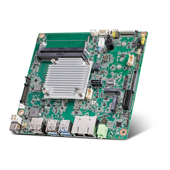
Introduction The AIMB-218 with Intel Pentium J6425, Celeron J6413, Celeron N6211, and Atom x6413E processor is designed for industrial applications that require enhanced com- puting performance and power management capabilities. The motherboard features an onboard Intel® Pentium™ J6425 quad-core 1.8 GHz and Celeron J6413 quad- core 1.8 GHz and Celeron N6211 dual-core 1.2 GHz and Atom x6413E quad-core 1.5 GHz with DDR4 3200 MHz up to 32GB. -
Page 13: Input/Output
1.3.3 Input/Output PCI bus: One PCIe x1 slot, one M.2 2242/3042/2280 (B Key) and one M.2 2230 (E sky) socket Serial ports: Six serial ports; COM1 support 5V/12V selection; COM2 support RS-232/422/485, set by Jumper; COM3~COM6 support RS-232 (COM3~6 BOM option) USB port: Supports three USB 3.2 Gen2 port with a transmission rates of up to ... -
Page 14: Jumpers And Connectors
Jumpers and Connectors Connectors on the AIMB-218 motherboard link it to external devices such as hard disk drives. In addition, the board has a number of jumpers used to configure your system for your application. The tables below list the function of each of the board jumpers and connectors. Later sections in this chapter give instructions on setting jumpers. - Page 15 Table 1.1: Connector / Header List Buzzer Power LED Pin Header JFP2 eDP/LVDS Backlight Inverter Power Connector INV1 SATA Power Connector SATA_PWR1 SYSTEM FAN Power Connector SYSFAN1 DDR4 SO-DIMM Socket DIMMA1 DDR4 SO-DIMM Socket DIMMB1 MPS’s I2C/SMBUS Programming for +VCCIN Controller JSMB1 eDP/LVDS Panel Connector LVDS_EDP1...
-
Page 16: Board Layout: Jumper And Connector Locations
Board Layout: Jumper and Connector Locations Figure 1.1 Jumper and Connector Locations AIMB-218 User Manual... -
Page 17: Aimb-218 Board Diagram
Figure 1.2 I/O Connectors AIMB-218 Board Diagram Figure 1.3 AIMB-218 Board Diagram AIMB-218 User Manual... -
Page 18: Safety Precautions
Safety Precautions Warning! Always completely disconnect the power cord from the chassis when working with the hardware. Do not connect devices while the power is on. Sensitive electronic components can be damaged by sudden power surges. Only experienced electronics personnel should open the PC chassis. -
Page 19: Cmos Mode Selection (Jcmos1)
1.8.2 CMOS Mode Selection (JCMOS1) The AIMB-218 motherboard contains a jumper that can erase CMOS data and reset the system BIOS information. To reset the CMOS data, Put jumper to Pins 2 & 3 as closed for a few seconds. This procedure resets the CMOS to its default settings. Table 1.3: CMOS Mode Selection (JCMOS1) Function Jumper Setting... -
Page 20: Edp/Lvds Panel Voltage Selection (Jlvds1)
1.8.4 eDP/LVDS Panel Voltage Selection (JLVDS1) Table 1.5: eDP/LVDS Panel Voltage Selection (JLVDS1) Function Jumper Setting Jumper position for +3.3V (Default) Jumper position for +5V Jumper position for +12V 1.8.5 PSON1: ATX and AT Mode Selector Table 1.6: PSON1: ATX and AT Mode Selector Function Jumper Setting ATX Mode (Default) -
Page 21: Jwdt1 + Jobs1: Watchdog Timer Output And Obs Beep
System reset input# SIO Warning Beep output SP1 Buzzer Beep input 1.8.7 Case Open Pin Header Selection (JCASEOP_SW1) Table 1.8: Case Open Pin Header Selection (JCASEOP_SW1) Function Jumper Settings (Default) Signal Pin Definition Normal Open Advantech define Normal Close AIMB-218 User Manual... -
Page 22: Power Switch/Hdd Led/Smbus/Speaker Pin Header (Jfp1)
1.8.8 Power Switch/HDD LED/SMBus/Speaker Pin Header (JFP1) Table 1.9: Power Switch/HDD LED/SMBus/Speaker Pin Header (JFP1) Function Jumper Settings Internal Buzzer(7-10) (Default) Signal Pin Definition Signal Pin Definition HDDLED+ Power Button+ HDDLED- Power Button- SPK_P3 SMB_DATA System Reset+ SPK_P4 SMB_CLK System Reset- 1.8.9 LVDS JEIDA/VESA Selection (JLVDS_VCON1) Table 1.10: LVDS JEIDA/VESA Selection (JLVDS_VCON1) -
Page 23: Com1 5V/12V/Ri# Selection (Jsetcom1_V1)
Table 1.11: COM1 5V/12V/RI# selection (JSETCOM1_V1) Function Jumper Settings Jumper position for RI# (Default) Jumper position for +5V Jumper position for +12V Signal Pin Definition Signal Pin Definition RI# [1] Advantech define Advantech define +12V Advantech define AIMB-218 User Manual... - Page 24 AIMB-218 User Manual...
-
Page 25: Chapter 2 Connecting Peripherals
Chapter Connecting Peripherals... -
Page 26: Introduction
Introduction Most of the device connectors can be accessed from the top of the board during installation in the chassis. If the system is installed with several cards or the chassis is packed, partial removal of the card may be necessary to make all connections. DC input DC-Jack Connector (DCIN1) &... -
Page 27: Usb Connector (Usb12/Usb34/Usb56/Usb78)
USB Connector (USB12/USB34/USB56/USB78) AIMB-218 provides up to three USB 3.2 Gen2 and five USB 2.0 ports. (USB12/ USB34/USB56/USB78. Four USB are located on the rear side, and four USB 2.0 are located internally. The USB interface complies with the USB specification revision 2.0 that supports transmission rates of up to 480 Mbps, revision 3.2 Gen2 that supports transmission rates of up to 10 Gbps, and is also fuse protected. -
Page 28: Front Hd Analog Audio Interface (Fpaud1)
Front HD Analog Audio Interface (FPAUD1) This connector is for a chassis-mounted front-panel audio I/O module that supports. HD audio. This connector is attached using the front panel audio I/O module cable. HD Analog Audio Interface Line-Out (AUDIO1) AIMB-218 User Manual... -
Page 29: Hd Digital Audio Interface (Spdif1)
HD Digital Audio Interface (SPDIF1) Audio Amplifier Output Connector (AMP1) BOM optional AIMB-218 User Manual... -
Page 30: Pci Express X1 Slot (Pciex1_1)
2.10 PCI Express X1 Slot (PCIEX1_1) 2.11 NGFF M.2 E-Key connector for 2230 module (M2E1) AIMB-218 User Manual... -
Page 31: Ngff M.2 B-Key Connector For 2242/2280/3042 Module (M2B1)
2.12 NGFF M.2 B-Key connector for 2242/2280/3042 module (M2B1) 2.13 SATA Signal Connector (SATA1) & SATA Power Connector (SATA_PWR1) AIMB-218 User Manual... -
Page 32: Serial Ports (Com1 ~ Com6)
2.14 Serial Ports (COM1 ~ COM6) AIMB-218 supports six serial ports. COM2 is RS-232/422/485 and COM1/3/4/5/6 are RS-232. COM1 also supports 5 V/12 V according to jumper selection. Users can employ JSETCOM2 to select between the RS-232/422/485 modes for COM2. Such ports can be connected to serial devices, such as a mouse or printer, or to a commu- nications network. -
Page 33: Spi Programming Pin Header (Spi_Cn1)
2.16 SPI Programming Pin Header (SPI_CN1) 2.17 SPI BIOS Flash Socket (SPI1) AIMB-218 User Manual... -
Page 34: Espi Pin Header (Espi1)
2.18 ESPI Pin Header (ESPI1) 2.19 8-bits General Purpose I/O Pin Header (GPIO1) AIMB-218 User Manual... -
Page 35: Low-Voltage Differential Signaling Interface & Embedded Displayport (Lvds_Edp1)
2.20 Low-voltage differential signaling interface & Embedded displayport (LVDS_EDP1) 2.21 LVDS Backlight Inverter Power Connector (INV1) AIMB-218 User Manual... -
Page 36: System Fan Power Connector (Sysfan1)
2.22 SYSTEM FAN Power Connector (SYSFAN1) 2.23 DDR4 SO-DIMM Socket (DIMMA1/DIMMB1) AIMB-218 User Manual... -
Page 37: Atx Power Supply (5Vsb) Connector (Atx_5Vsb1)
2.24 ATX Power supply (5VSB) connector (ATX_5VSB1) 2.25 Front Panel Connectors (JFP1) Several external switches are provided for monitoring and controlling the AIMB-218. 2.25.1 ATX Soft Power Switch (JFP1/PWR_SW) For computer cases equipped with ATX power supply, users should connect the Power On/Off button on the computer case to (JFP1 + JFP2/PWR_SW) for conve- nient Power On/Off functionality. -
Page 38: Reset (Jfp1/Reset)
2.25.2 Reset (JFP1/RESET) Many computer cases offer the convenience of a specific reset button. Connect the wire for the reset button. 2.25.3 HDD LED (JFP1/HDDLED) An LED can be linked to the connector (JFP2/HDDLED) to indicate when the HDD is active. -
Page 39: Bios Operation
Chapter BIOS Operation... -
Page 40: Introduction
AIMB-218 setup screens. BIOS Setup The AIMB-218 Series system has AMI BIOS built in, with a CMOS SETUP utility that allows users to configure required settings or to activate certain system features. The CMOS SETUP saves the configuration in the CMOS RAM of the motherboard. When the power is turned off, the battery on the board supplies the necessary power to pre- serve the CMOS RAM. -
Page 41: Main Menu
3.2.1 Main Menu Press <Del> to enter AMI BIOS CMOS Setup Utility, the Main Menu will appear on the screen. Use arrow keys to select among the items and press <Enter> to accept or enter the sub-menu. The Main BIOS setup screen has two main frames. The left frame displays all the options that can be configured. -
Page 42: Advanced Bios Features
3.2.2 Advanced BIOS Features Select the Advanced tab from the AIMB-218 setup screen to enter the Advanced BIOS Setup screen. You can select any of the items in the left frame of the screen, such as CPU Configuration, to go to the sub menu for that item. You can display an Advanced BIOS Setup option by highlighting it using the <Arrow>... - Page 43 3.2.2.1 Trusted Computing To enable/disable TPM 2.0 set up in BIOS. TPM (Trusted Platform Module) is a secure key generator and key cache management component, enables protected storage of encryption keys and authentication credentials for enhanced security capabilities. Security Device Support [Disable] ...
- Page 44 3.2.2.2 ACPI Settings Enable ACPI Auto Configuration [Disabled] Enable or disable BIOS ACPI auto configuration. Enable Hibernation [Enabled] Enables or Disables System ability to Hibernate (OS/S4 Sleep State). This option may be not effective with some OS. ACPI Sleep State [Auto] ...
- Page 45 3.2.2.3 PCH Configuration Firmware update Configuration ME FW Image Re-Flash [Disabled] AIMB-218 User Manual...
- Page 46 3.2.2.4 NCT6126D Super IO Configuration Super IO Chip [NCT6126D] AIMB-218 User Manual...
- Page 47 Serial Port 1 Configuration Serial Port [Enabled] Device Settings: IO=3F8h; IRQ =4 Change Settings [Auto] Select an optimal setting for serial port 1. AIMB-218 User Manual...
- Page 48 Serial Port 2 Configuration Serial Port [Enabled] Device Settings: IO=2F8h; IRQ =3 Change Setting [Auto] Select an optimal setting for serial port 2. Device Mode [RS232] AIMB-218 User Manual...
- Page 49 Serial Port 3 Configuration Serial Port [Enabled] Device Settings: IO=3F8h; IRQ =5 Change Setting [Auto] Select an optimal setting for serial port 2. AIMB-218 User Manual...
- Page 50 Serial Port 4 Configuration Serial Port [Enabled] Device Settings: IO=2E8h; IRQ =7 Change Setting [Auto] Select an optimal setting for serial port 4. AIMB-218 User Manual...
- Page 51 Serial Port 5 Configuration Serial Port [Enabled] Device Settings: IO=220h; IRQ =10 Change Setting [Auto] Select an optimal setting for serial port 5. AIMB-218 User Manual...
- Page 52 Serial Port 6 Configuration Serial Port [Enabled] Device Settings: IO=228h; IRQ =11 Change Setting [Auto] Select an optimal setting for serial port 6. AIMB-218 User Manual...
- Page 53 Digital I/O Configuration Digital I/O Pin 1 - 8 [Input] AIMB-218 User Manual...
- Page 54 3.2.2.5 NCT6126D HW Monitor CPU Warning Temperature [Disabled] Use this to set the CPU warning temperature threshold. When the system reaches the warning temperature, the speaker will beep. ACPI Shutdown Temperature [Disabled] Use this to set the ACPI shutdown temperature threshold. When the system reaches the shutdown temperature, it will be automatically shut down by ACPI OS to protect the system from overheating damage.
- Page 55 Smart Fan Mode Configuration SYSFAN Mode [SMART FAN IV Mode] The item shows you system temperature and fan speed (PWM) information. AIMB-218 User Manual...
- Page 56 3.2.2.6 S5 RTC Wake Settings The item allows you enable or disable system wake up on alarm event. Wake system with Fixed Time [Disabled] Note! When enabled, system will wake up on the specified time. AIMB-218 User Manual...
- Page 57 3.2.2.7 Serial Port Console Redirection Console Redirection [Disabled] Enable or disable the console redirection feature. AIMB-218 User Manual...
- Page 58 3.2.2.8 Network Stack Configuration [Disabled] Network Stack [Disabled] When network stack [enable], item must enable: LANx PXE OpROM Note! [enable]. AIMB-218 User Manual...
- Page 59 3.2.2.9 USB Configuration Legacy USB Support [Enabled] Enables support for legacy USB. Auto option disables legacy support if no USB devices are connected. XHCI Hand-off [Enabled] USB Mass Storage Driver Support [Enabled] USB hardware delays and time-outs ...
-
Page 60: Chipset Configuration Setting
Chipset Configuration Setting Select the chipset tab from the BIOS setup screen to enter the Chipset Setup screen. Users can select any item in the left frame of the screen, such as PCI express Con- figuration, to go to the sub menu for that item. Users can display a Chipset Setup option by highlighting it using the <Arrow>... -
Page 61: System Agent (Sa) Configuration
3.3.1 System Agent (SA) Configuration VT-d [Enabled] Disable or enable VT-d function on MCH. AIMB-218 User Manual... - Page 62 3.3.1.1 Memory Configuration The item shows you memory specification included RC version, Frequency, size and voltage information etc. Max TOLUD [Dynamic] Maximum Value of TOLUD. Dynamic assignment would adjust TOLUD automat- ically based on largest MMIO length of installed graphic controller. Fast Boot [Enabled] ...
- Page 63 3.3.1.2 Graphics Configuration Skip Scanning of External Gfx Card [disabled] Primary Display [Auto] Select which of IGFX/PEG/PCI Graphics device should be the Primary Display. Internal Graphics [Auto] Keep IGD enabled based on the setup options. GTT size [8MB] ...
- Page 64 LCD Control LVDS Panel Type [Disabled] Panel Scaling [Auto] Panel Color Depth [18 Bit] AIMB-218 User Manual...
-
Page 65: Pch-Io Configuration
3.3.2 PCH-IO Configuration PCI Express Configuration Details of PCI Express items. (See 3.3.2.1.) Security Configuration Details of BIOS security items. (See 3.3.2.3.) LAN 1controller [Enabled] Enable or disable the LAN 1 controller. LAN 2 controller [Enabled] Enable or disable the LAN 2 controller. - Page 66 3.3.2.1 PCI Express Configuration PCH PCI Express Clock Gating [Platform-POR] Enable or Disable PCI Express clock gating for each port. AIMB-218 User Manual...
- Page 67 LAN1 Controller LAN1 Controller [Enabled] Controls the LAN1 controller Root Port. ASPM Support [Auto] Sets the ASPM Level: Force L0s - Force all links to L0s State: AUTO - BIOS. auto configure: DISABLE - Disables ASPM. L1 Substates PCI Express L1 Substates settings [L1.1 & L1.2] ...
- Page 68 LAN2 Controller LAN2 Controller [Enabled] Controls the LAN2 controller Root Port. ASPM Support [Auto] Sets the ASPM Level: Force L0s - Force all links to L0s State: AUTO - BIOS. auto configure: DISABLE - Disables ASPM. L1 Substates PCI Express L1 Substates settings [L1.1 & L1.2] ...
- Page 69 M.2 B-key slot PCIE x1/M.2 B-Key slot [Enabled] Controls the PCIE x1/M.2 B-Key Root Port. ASPM [Auto] Sets the ASPM Level: Force L0s - Force all links to L0s State: AUTO - BIOS. auto configure: DISABLE - Disables ASPM. L1 Substates PCI Express L1 Substates settings [L1.1 &...
- Page 70 M.2 E-key slot M.2 E-Key slot [Enabled] Controls the M.2 E-Key Root Port. ASPM [Auto] Sets the ASPM Level: Force L0s - Force all links to L0s State: AUTO - BIOS. auto configure: DISABLE - Disables ASPM. L1 Substates PCI Express L1 Substates settings [L1.1 &...
- Page 71 3.3.2.2 SATA and RST Configuration AIMB-218 User Manual...
-
Page 72: Security Setting
Security Setting Administrator Password Select this option and press <ENTER> to access the sub menu, and then type in the password. Set the Administrator password. User Password Select this option and press <ENTER> to access the sub menu, and then type in the password. -
Page 73: Boot Setting
Boot Setting Setup Prompt Timeout Use the <+> and <-> keys to adjust the number of seconds to wait for setup acti- vation key. Bootup NumLock State [On] On or Off power on state for the NumLock. Quiet Boot [Disabled] ... -
Page 74: Save & Exit Configuration
Save & Exit Configuration Save Changes and Exit When users have completed system configuration, select this option to save changes, exit BIOS setup menu and reboot the computer to take effect all sys- tem configuration parameters. (1) Select Exit Saving Changes from the Exit menu and press <Enter>. The fol- lowing message appears: Save Configuration Changes and Exit Now? [Ok] [Cancel] (2) Select Ok or cancel. - Page 75 (1) Select Reset Discarding Changes from the Exit menu and press <Enter>. The following message appears: Discard Changes and Exit Setup Now? [Ok] [Cancel] (2) Select Ok to discard changes and reset. Discard Changes Select Discard Changes from the Exit menu and press <Enter>. Restore Default ...
- Page 76 AIMB-218 User Manual...
-
Page 77: Software And Service Introduction
Chapter Software and Service Introduction... -
Page 78: Introduction
Introduction The mission of Advantech Embedded Software Services is to “enhance users’ quality of life with Advantech platforms and Microsoft® Windows® embedded technology”. We equip Advantech platforms with Windows® embedded software products to more effectively support the embedded computing community. This eliminates the hassle of dealing with multiple vendors (hardware suppliers, system integrators, and embed- ded OS distributors) for specific projects. - Page 79 Backlight The Backlight API allows developers to control the backlight (screen) in embedded devices. 4.2.1.3 Monitor Watchdog A watchdog timer is a device that performs a specific opera- tion after a specified period of time when a malfunction occurs and the system cannot recover on its own. A watch- dog timer can be programmed to perform a warm booting (system restart) after a certain number of seconds.
-
Page 80: Software Utility
4.2.2 Software Utility BIOS Flash The BIOS Flash utility allows customers to update the flash ROM BIOS version, or backup the current BIOS by copying the configuration from the flash chip to a file on the users’ disk. The BIOS Flash utility also features a com- mand line version and API for rapid implementation in cus- tomized applications. -
Page 81: Chipset Software Install Utility
Chapter Chipset Software Install Utility... -
Page 82: Before Installation
Before installing the enhanced display drivers and utility software, please read the instructions provided in this chapter carefully. The drivers for AIMB-218 are provided on Advantech support website: http://support.advantech.com/Support/. This driver will guide and link users to the utilities and drivers required for Microsoft Windows- based systems. -
Page 83: Graphics Setup
Chapter Graphics Setup... -
Page 84: Introduction
Introduction To benefit from the Intel® Pentium J6425, Celeron J6413, Celeron N6211, Atom x6413E integrated graphics controller, users must install the graphics driver. Windows 10 Note! Before installing this driver, ensure the CSI utility is installed on the sys- tem. See Chapter 5 for information regarding installing the CSI utility. Download the driver from website on your computer. -
Page 85: Lan Configuration
Chapter LAN Configuration... -
Page 86: Introduction
Introduction The AIMB-218 system features dual Gigabit Ethernet LANs via dedicated PCI Express x1 lanes (Realtek RTL8111H (LAN1) and Realtek RTL8111H (LAN2)) that offer a bandwidth of up to 500 MB/sec, eliminating bottlenecks in the flow of network data by incorporating Gigabit Ethernet at 1000 Mbps. Features Integrated 10/100/1000 Mbps transceiver ... -
Page 87: Appendix A Pin Assignments
Appendix Pin Assignments... -
Page 88: Dc Input Phoenix Connector (Dcin1)
DC Input Phoenix Connector (DCIN1) Signal Pin Definition Power input (Only +12V) DisplayPort High (DP1+HDMI1) Definition Multimedia Interface (DP1+HDMI1) Signal Pin Definition Signal Pin Definition HDMI1_Z_D2+ DP1_0+ HDMI1_Z_D2- DP1_0- HDMI1_Z_D1+ DP1_1+ HDMI1_Z_D1- DP1_1- HDMI1_Z_D0+ DP1_2+ HDMI1_Z_D0- DP1_2- HDMI1_Z_CLK+ DP1_3+ HDMI1_Z_CLK- DP1_3- DP1_AUX_EN# HDMI1_SCL... -
Page 89: Usb 3.0+2.0 Stack Connector (Usb34)
USB 3.0+2.0 Stack Connector (USB34) Signal Pin Definition Signal Pin Definition USB2_D3- USB2_D2- USB2_D3+ USB2_D2+ USB31_P3_z_RX- USB31_P3_z_RX+ USB31_P3_z_TX- USB31_P3_z_TX+ USB 3.0 Stack Connector (USB34) Signal Pin Definition Signal Pin Definition USB2_D0- USB2_D1- USB2_D0+ USB2_D1+ USB31_P0_z_RX- USB31_P1_z_RX- USB31_P0_z_RX+ USB31_P1_z_RX+ USB31_P0_z_TX- USB31_P1_z_TX- USB31_P0_z_TX+ USB31_P1_z_TX+ AIMB-218 User Manual... -
Page 90: Rj45 1 Port (Lan1)
RJ45 1 Port (LAN1) Signal Pin Definition LAN1_MDI0+ LAN1_MDI0- LAN1_MDI1+ LAN1_MDI1- LAN1_CONN LAN1_CT LAN1_MDI2+ LAN1_MDI2- LAN1_MDI3+ LAN1_MDI3- LAN1_LED1_ACT#_R +V3.3_DUAL LAN1_LED2_1G#_R LAN1_LED0_100M#_R AIMB-218 User Manual... -
Page 91: Rj45 2 Port (Lan12)
RJ45 2 Port (LAN12) Signal Pin Definition Signal Pin Definition LAN1_MDI0+ LAN2_MDI0+ LAN1_MDI0- LAN2_MDI0- LAN1_MDI1+ LAN2_MDI1+ LAN1_MDI1- LAN2_MDI1- LAN1_CONN LAN2_CONN LAN1_CT LAN2_CT LAN1_MDI2+ LAN2_MDI2+ LAN1_MDI2- LAN2_MDI2- LAN1_MDI3+ LAN2_MDI3+ AR10 LAN1_MDI3- BR10 LAN2_MDI3- LAN1_LED1_ACT#_R LAN2_LED0_ACT#_R +V3.3_DUAL +V3.3_DUAL LAN1_LED2_1G#_R LAN2_LED2_1G#_R LAN1_LED0_100M#_R LAN2_LED0_100M#_R Front HD Analog Audio Interface (FPAUD1) Signal Pin Definition Signal Pin Definition... -
Page 92: Hd Analog Audio Interface Line-Out (Audio1)
HD Analog Audio Interface Line-Out (AUDIO1) Signal Pin Definition LINE-Out A.10 HD Digital Audio Interface (SPDIF1) Signal Pin Definition SPDIF OUT A.11 Audio Amplifier Output Connector (AMP1) Signal Pin Definition SPK_R+ SPK_R- SPK_L- SPK_L+ AIMB-218 User Manual... -
Page 93: Pci Express X1 Slot (Pciex1_1)
A.12 PCI Express X1 Slot (PCIEX1_1) Signal Pin Definition Signal Pin Definition +12V PRSNT1# +12V +12V +12V +12V SMB_CLK Reserved SMB_DATA Reserved Reserved +3.3V Reserved Reserved +3.3V +3.3VAUX +3.3V WAKE# PWRGD Reserved REFCLK+ TX0+ REFCLK- TX0- RX0+ Reserved RX0- DETECT# TX1+ CONFIG1 TX1-... -
Page 94: Ngff M.2 E-Key Connector For 2230 Module (M2E1)
A.13 NGFF M.2 E-Key Connector for 2230 Module (M2E1) Signal Pin Definition6 Signal Pin Definition +3.3V USB_D+ +3.3V USB_D- WiFi_LED# (I)(OD) I2S SCK (O/I)(0/1.8V) I2S WS (I/O)(0/1.8V) I2S SD_IN (I)(0/1.8V) I2S SD_OUT (O)(0/1.8V) BT_LED# (I)(OD) UART WAKE# (I)(0/3.3V) UART RXD (I)(0/1.8V) Connector KEY Connector KEY Connector KEY... -
Page 95: Sata Signal Connector (Sata1)
A.14 SATA Signal Connector (SATA1) Signal Pin Definition AIMB-218 User Manual... -
Page 96: Ngff M.2 B-Key Connector For 2242/2280/3042 Module (M2B1)
A.15 NGFF M.2 B-Key Connector for 2242/2280/3042 Module (M2B1) Signal Pin Definition6 Signal Pin Definition CONFIG_3 +3.3V +3.3V FULL_CARD_POWER_OFF# USB_D+ W_DISABLE1# USB_D- Connector KEY Connector KEY Connector KEY Connector KEY Connector KEY Connector KEY Connector KEY Connector KEY CONFIG_0 PCIE_WAKE# M.2_GNSS_DISABLE# PERn1/USB3.0-Rx- UIM-RESET (I) -
Page 97: Usb 2.0 Pin Header (Usb56)
A.16 USB 2.0 Pin Header (USB56) Signal Pin Definition Signal Pin Definition USB2_D5- USB2_D6- USB2_D5+ USB2_D6+ RESERVED AIMB-218 User Manual... -
Page 98: Com 4 Port (Com3456)
A.17 COM 4 Port (COM3456) Signal Pin Definition Signal Pin Definition DCD# [3] DSR# [3] RXD [3] RST# [3] TXD [3] CTS# [3] DTR# [3] RI# [3] DCD# [4] DSR# [4] RXD [4] RST# [4] TXD [4] CTS# [4] DTR# [4] RI# [4] DCD# [5] DSR# [5]... -
Page 99: Sim Card Connector (Sim1)
A.18 SIM Card Connector (SIM1) Signal Pin Definition UIM_PWR UIM_RESET UIM_CLK UIM_VPP UIM_DATA A.19 SPI Programming Pin Header (SPI_CN1) Signal Pin Definition Signal Pin Definition +3.3V MISO MOSI AIMB-218 User Manual... -
Page 100: Spi Bios Flash Socket (Spi1)
A.20 SPI BIOS Flash Socket (SPI1) Signal Pin Definition Signal Pin Definition MOSI MISO WP# / IO2 HOLD# / IO3 +3.3V A.21 USB 2.0 Pin Header (USB78) Signal Pin Definition Signal Pin Definition USB2_D7- USB2_D8- USB2_D7+ USB2_D8+ RESERVED A.22 ESPI Pin Header (ESPI1) Signal Pin Definition Signal Pin Definition ESPI1_CLK... -
Page 101: 8-Bit General Purpose I/O Pin Header (Gpio1)
A.23 8-bit General Purpose I/O Pin Header (GPIO1) Signal Pin Definition Signal Pin Definition GPIO0 GPIO4 GPIO1 GPIO5 GPIO2 GPIO6 GPIO3 GPIO7 +V5_DUAL A.24 Case-Open Detect Connector (JCASE1) Signal Pin Definition Case Open A.25 COM 2 Port (COM12) Signal Pin Definition Signal Pin Definition DCD# [1] DSR# [1]... -
Page 102: Power Led Pin Header (Jfp2)
A.26 Power LED Pin Header (JFP2) Signal Pin Definition SIO_SUSLED_R SIO_SUSLED A.27 LVDS Backlight Inverter Power Connector (INV1) Signal Pin Definition +12V BKL_EN BKL_CTRL A.28 SATA Power Connector (SATA_PWR1) Signal Pin Definition +V12 AIMB-218 User Manual... -
Page 103: System Fan Power Connector (Sysfan1)
A.29 SYSTEM FAN Power Connector (SYSFAN1) Signal Pin Definition SYSTEM FAN VCC SYSTEM FAN SPEED SYSTEM FAN PWM A.30 MPS’s I2C/SMBUS Programming for +VCCIN Controller (JSMB1) Signal Pin Definition TPS53655_SMB_CLK TPS53655_SMB_DIO AIMB-218 User Manual... -
Page 104: Low-Voltage Differential Signaling Interface (Lvds_Edp1)
A.31 Low-Voltage Differential Signaling Interface (LVDS_EDP1) Signal Pin Definition Signal Pin Definition LVDS_DET# CLK1N CLK2N CLK1P CLK2P ENBKL VCON AIMB-218 User Manual... -
Page 105: Embedded Displayport (Lvds_Edp1)
A.32 Embedded Displayport (LVDS_EDP1) Signal Pin Definition Signal Pin Definition EDP_TXN2 EDP_TXP2 EDP_TXN1 EDP_TXP1 EDP_TXN3 EDP_TXP3 EDP_AUX+ EDP_AUX- EDP_ HPD A.33 ATX Power Supply (5VSB) Connector (ATX_5VSB1) Signal Pin Definition +V5SB PS_ON# AIMB-218 User Manual... -
Page 106: Atx 12V Power Supply Connector (Atx12V1)
A.34 ATX 12V Power Supply Connector (ATX12V1) Signal Pin Definition +12V +12V AIMB-218 User Manual... - Page 107 AIMB-218 User Manual...
- Page 108 No part of this publication may be reproduced in any form or by any means, electronic, photocopying, recording or otherwise, without prior written permis- sion from the publisher. All brand and product names are trademarks or registered trademarks of their respective companies. © Advantech Co., Ltd. 2021...
Need help?
Do you have a question about the AIMB-218 Series and is the answer not in the manual?
Questions and answers