
Related Manuals for KYLAND Opal8 Series


Summary of Contents for KYLAND Opal8 Series
- Page 1 Opal5/Opal8 Series Entry-Level Industrial Ethernet Switch Hardware Installation Manual Publication Date: Nov. 2018 Version: V1.4 No.: 112023031...
- Page 2 All rights reserved. No part of this documentation may be excerpted, reproduced, translated, annotated or duplicated, in any form or by any means without the prior written permission of Kyland Corporation. Copyright © 2018 Kyland Technology Co., Ltd.
- Page 3 Before using the device, read this notice carefully for personal and equipment safety. Please keep the manual for further reference. If the device used not according to the specified way by Kyland, the protection provided by the device maybe diminished. A Kyland is not liable to any personal or equipment damage caused by violation of this notice.
- Page 4 Dispose of the device in accordance with relevant national provisions, preventing environmental pollution. In the following cases, please immediately shut down your power supply and contact your Kyland representative: Water gets into the equipment. Equipment damage or shell damage.
-
Page 5: Table Of Contents
Contents 1 Product Overview..........................2 2 Structure and Interface........................4 2.1 Front Panel..........................4 2.2 Top Panel...........................4 3 Mounting............................5 3.1 Dimension Drawing........................5 3.2 Mounting Modes and Steps....................5 3.2.1 DIN-Rail Mounting......................6 3.2.2 DIN-Rail Dismounting....................... 6 4 Connection............................7 4.1 10/100Base-T(X) Ethernet Port....................7 4.2 100Base-FX Ethernet Port...................... -
Page 6: Product Overview
SMSFP= Single mode 100Base-X SFP module plugged into SFP slot MMSFP= Multi mode 100Base-X SFP module plugged into SFP slot N/A= No SFP module plugged into SFP slot PS1-PS2: power LV-LV=24VAC/DC (18-30VAC, 50/60Hz; 12-48VDC), redundant power input) input Kyland Opal5/Opal8 IM-EN-June 2016... - Page 7 LV-LV=24VAC/DC (18-30VAC, 50/60Hz; 12-48VDC), redundant power input) input Note: We reserve the right to amend the product information listed in this table without notice. To obtain the latest information, you can contact our sales or technical support personnel. Kyland Opal5/Opal8 IM-EN-June 2016...
-
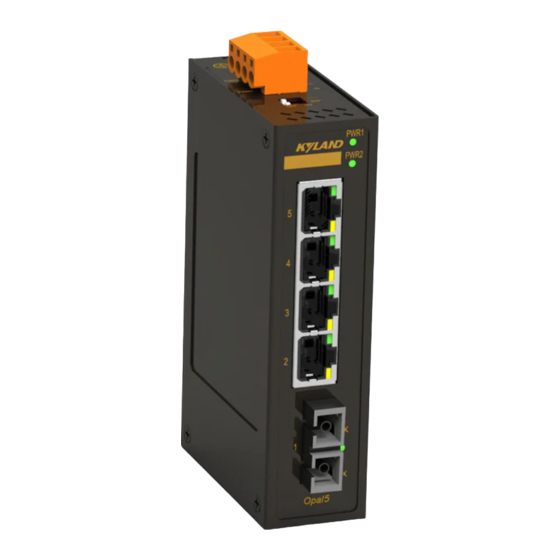
Page 8: Structure And Interface
(4) 10/100Base-T(X) Ethernet port connection status LED (green) (5) 10/100Base-T(X) Ethernet port speed LED (yellow) (6) 100Base-FX Ethernet port and its connection status LED (7) 100Base-X SFP slot and its connection status LED 2.2 Top Panel Figure 2 Top Panel Kyland Opal5/Opal8 IM-EN-June 2016... -
Page 9: Mounting
Please use caution when coming in contact and avoid covering the switch housing when the switch is running. The figures in this manual are only for reference. 3.2 Mounting Modes and Steps The device supports DIN-rail mounting. Before installation, make sure that the following requirements are met. Kyland Opal5/Opal8 IM-EN-June 2016... -
Page 10: Din-Rail Mounting
1 until the bottom of the device is detached from the DIN rail. Step 2: Pull the device upward and move the device in direction 2 until the device is removed from the DIN rail completely. Figure 6 DIN Rail Dismounting Kyland Opal5/Opal8 IM-EN-June 2016... -
Page 11: Connection
Receive Data- (RD-) Transmit Data- (TD-) Transmit Data+ (TD+) Receive Data+ (RD+) Transmit Data- (TD-) Receive Data- (RD-) 4,5,7,8 Unused Unused Note: "+" and "-" indicate level polarities. Wiring Sequence Figure 8 Connection Using Straight-through/Cross-over Cable Kyland Opal5/Opal8 IM-EN-June 2016... -
Page 12: 100Base-Fx Ethernet Port
Table 4 SFP Optical Modules for 100Base-X SFP slot Transmission Model Interface Connector Manufacturer Distance HSFP-03-3312M-22F 100Base-FX port HI-OPTEL HSFP-03-3312S-22F 100Base-FX port 20km HI-OPTEL OP3220D 100Base-X port 20km OPWAY OP3202D 100Base-X port OPWAY The center Wavelength (CWL) of SFP module above is 1310nm. Kyland Opal5/Opal8 IM-EN-June 2016... - Page 13 If the LED is off, the link is not connected. This may be caused by incorrect connection of the TX and RX ports. In this case, swop the two connectors in the one end of the optical fiber. Kyland Opal5/Opal8 IM-EN-June 2016...
-
Page 14: Grounding
All field wiring intended for connection to the power terminal shall consist of copper conductors with the insulation locally removed. Additional intermediate connecting parts, other than ferrules, shall not be used. The exposed power cable wires connecting the plug-in terminal block should be 3-5mm approximately. Kyland Opal5/Opal8 IM-EN-June 2016... - Page 15 If the power LED on the front panel of the switch turns on, the power supply is connected properly. Wiring and mounting should meet following specifications. Table 6 Wiring and Mounting Specifications Terminal Type Required Torque Wire Range (AWG) Terminal Block Plug 4.5-5.0 lb-in 12-24 Kyland Opal5/Opal8 IM-EN-June 2016...
-
Page 16: Dip Switches
OFF. The function of the DIP switches is shown in the following table. Figure 14 DIP Switches Table 7 Description of the DIP Switches DIP Switches State Description Enable broadcast storm protection Ⅰ Disable broadcast storm protection Reserved Ⅱ Kyland Opal5/Opal8 IM-EN-June 2016... -
Page 17: Leds
No effective port connection 10/100Base-T(X) Ethernet port 100M working state (100Base-TX) speed LED (yellow) 10M working state or no connection Effective port connection 10/100Base-T(X) Ethernet port Blinking Ongoing network activities connection status LED (green) No effective port connection Kyland Opal5/Opal8 IM-EN-June 2016... -
Page 18: Basic Features And Specifications
Opal8: 0.3Kg Environmental Limits Applicable Environmental Indoor -10℃ ≤ Tamb ≤ 60℃ Opal5-E series, Opal8-E series Ambient Temperature -40℃ ≤ Tamb ≤ 75℃ Opal5 series, Opal8 series Storage Temperature -40℃~+85℃ Ambient Relative Humidity 5%~95% (no condensing) Pollution degree Altitude 2000m... -
Page 19: Certificates Used For Compliance
Certificates Used for Compliance 7 Certificates Used for Compliance Certificates Approvals FCC 47CFR Part2 and part15 Class A Safety UL508/UL61010, Class1 Div2, ATEX/IECEx Kyland Opal5/Opal8 IM-EN-June 2016... -
Page 20: Appendix
IP 54 in accordance with EN IEC/IEC 60079-0 and enclosure only accessible with tool removable cover. Transient protection shall be provided that is set at a level not exceeding 140 % of the peak rated voltage value at the supply terminals to the equipment. Kyland Opal5/Opal8 IM-EN-June 2016... - Page 21 Provision shall be made to prevent the rated voltage from being exceeded by transient disturbances of more than 140% of the rated voltage. Suitable cable with temperature of 85.5℃ at least must be used for the power input terminal. Kyland Opal5/Opal8 IM-EN-June 2016...
- Page 22 Kyland Technology Co., Ltd. FAX: +86-10-88796678 Website: http://www.kyland.com Email: support@kyland.com Factory Address: BUILDING NO.2, SHIXING AVENUE30#, SHIJINGSHAN DIST, BEIJING 100041 CHINA...
Need help?
Do you have a question about the Opal8 Series and is the answer not in the manual?
Questions and answers