
Related Manuals for KYLAND SICOM3024P


Summary of Contents for KYLAND SICOM3024P
- Page 1 SICOM3024P Industrial Ethernet Switch Hardware Installation Manual Publication Date:Jul. 2014 Version: V2.8 No.: 112020094...
- Page 2 SICOM3024P Industrial Ethernet Switch Hardware Installation Manual Disclaimer: Kyland Technology Co., Ltd. tries to keep the content of this manual as accurate and as updated as possible. This document is not guaran- teed to be error-free, and we reserve the right to amend it without notice to users.
- Page 3 Artificial damage or destruction of the device should be avoided. Before using the device, read this notice carefully for personal and equipment safety. Please keep the manual for further reference. Kyland is not liable to any personal or equipment damage caused by violation of this notice. ●...
-
Page 4: Table Of Contents
Contents 1 Product Overview………………………………………………………………1 2 Structure and Interface…………………………………………………………2 2.1 Front Panel………………………………… … … … ……………… … … 3 2.2 Rear Panel…………………… … … … … … … … ………………… … … 3 3 Switch Installation…… … … … … … …… … … … … ………………… … …… 5 3.1 Dimension Drawing…………... -
Page 5: Product Overview
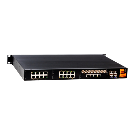
1 Product Overview SICOM3024P includes a series of managed industrial Ethernet switches tailored for power, rail transit, and coal mining industries. Capable of working properly in rugged environment, SICOM3024P conforms to IEC61850-3 and IEEE1613 standards and adopts internal modular design for flexible expansion. -
Page 6: Structure And Interface
Table 2 Models (without GX/GE) Note: We reserve the right to amend the product information listed in the table above without notice. To obtain the latest information, contact our sales or technical support personnel. 2 Structure and Interface Caution: It is recommended to purchase the port dustproof shield (optional) to keep ports clean and ensure switch performance. -
Page 7: Front Panel
2.1 Front Panel (1) (3) (7) (9) (2) (4) Figure 1 Front Panel 100M 100M 2.2 Rear Panel (10) (15) (16) (11) ( 12) (13) ( 14) (17) (2)(3) (18) ( 19) ( 20) (8) ( 9) (6) ( 7) Figure 2 Rear Panel... - Page 8 Table 3 Description of Rear Panel Note: Figure 2shows the rear panel of the device. The layout of Slot 1, Slot ● 2, and Slot 3 can be A, B, C, D, E, F, and the layout of Slot 4 can be G, H, I, J.
-
Page 9: Switch Installation
3 Switch Installation 3.1 Dimension Drawing 482.6 Figure 3 Dimension Drawing (unit: mm) Caution: As part of the heat dissipation system, the switch housing becomes ● hot during operation. Please use caution when coming in contact and avoid covering the switch housing when the switch is running. The figures in this chapter are only for reference. - Page 10 1) Environment:temperature (-40℃ to 85℃), ambient relative humidity (5% to 95%, non-condensing) 2) Power requirement:The power input is within the voltage range of the switch. 3) Grounding resistance:<5Ω 4) No direct sunlight, distant from heat source and areas with strong electro magnetic interference.
-
Page 11: Cable Connection
Mounting ● Step 1: Select the mounting position for the device and guarantee adequate space and heat dissipation for it (dimensions: 440mm×44mm×322.5mm). Step 2: Move the switch in direction 1 until the screw holes for securing the mounting brackets to rack posts are in alignment with the corresponding holes in the rack posts. -
Page 12: 100Base-Fx Port
Table 4 Pin Definitions of 10/100Base-T(X) RJ45 Port Wiring Sequence ● Straight-through Cable RJ45 RJ45 Crossover Cable RJ45 RJ45 Figure 8 Connection Using Straight-through/Cross-over Cable Note: The color of the cable for RJ45 connector meets the 568B standard: 1- orange and white, 2-orange, 3-green and white, 4-blue, 5-blue and white, 6-green, 7-brown and white, and 8-brown. -
Page 13: 100Base-X Sfp Slot
Figure 9 Cable Connection of 100Base-FX Port Caution: A laser is used to transmit signals in fiber cables. The laser meets the requirements of level 1 laser products. Routine operation is not harmful to your eyes, but do not look directly at the 100Base-FX Ethernet port when the switch is powered on. -
Page 14: 1000Base-X, 10/100/1000Base-T(X) Sfp Slot
Table 6 Pin Definitions of 10/100/1000Base-T(X) RJ45 Port Wiring Sequence ● Straight-through Cable RJ45 RJ45 Crossover Cable RJ45 RJ45 Figure 11 Connection Using Straight-through/Cross-over Cable Note: The color of the cable for RJ45 connector meets the 568B standard: 1- orange and white, 2-orange, 3-green and white, 4-blue, 5-blue and white, 6-green, 7-brown and white, and 8-brown. -
Page 15: Gigabit Sfp Optical Module
Table 7 Gigabit SFP Optical/Electrical Modules for 1000Base-X, 10/100/1000 Base-T(X) SFP slot 4.5.1 Gigabit SFP Optical Module Figure 12 Gigabit SFP Optical Module Gigabit SFP optical module is equipped with LC connector, and each port consists of a TX (transmit) port and an RX (receive) port. To enable communi- cation between Device A and Device B, connect the TX (transmit) port of Device A to the RX (receive) port of Device B, and the RX (receive) port of Device A to the TX (transmit) port of Device B. -
Page 16: Gigabit Sfp Electrical Module
How to Connect the SFP Optical Module ● Insert the SFP optical module into the SFP slot in the switch, and then plug the optical fiber into the TX port and RX port of the SFP module. SFP slot SFP optical module Optical fiber Figure 14 Connecting the Gigabit SFP Optical Module How to Determine the RX Port and TX Port of Gigabit SFP Optical Module... -
Page 17: Console Port
How to Connect the Gigabit SFP Electrical Module ● Insert the SFP electrical module into the SFP slot in the switch, and then plug the RJ45 connector of the twisted pair into the SFP module. SFP slot SFP Electrical module RJ45 connector Figure 16 Connecting the Gigabit SFP Electrical Module 4.6 Console Port... -
Page 18: Grounding
Facing the A direction Facing the B direction RJ45 connector DB9 connector Wiring sequence Figure 18 Wiring Sequence of DB9-RJ45 Console Cable Table 8 Pin Definitions of DB9 Port (9-Pin Serial Port) and RJ45 Port (Console Port) 4.7 Grounding Grounding protects the device from lightning and interference. Therefore, you must ground the device properly. -
Page 19: Power Terminal Block
4.8 Power Terminal Block There is a power terminal block on the rear panel of the switch.You need to connect the power cable to the terminal block to provide power for the switch. The device supports single (PWR1) and redundant (PWR1 and PWR2) power supply with a 5-pin 5.08mm-spacing plug-in terminal block. -
Page 20: Alarm Terminal Block
Caution: Before connecting the device to power supply, make sure that the power input meets the power requirement. If connected to an incorrect power input, the device may be damaged. Warning: Do not touch any exposed conducting wire, terminal, or component ●... -
Page 21: Leds
5 LEDs Table 10 Front Panel LEDs 100M 100M... - Page 22 Table 11 Rear Panel LEDs Speed (yellow) Connection status (green) Speed (yellow) Connection status (green)
-
Page 23: Switch Access
6 Switch Access You can access the switch in any of the following ways: 6.1 Access through Console Port Step 1: Connect the console port of the switch to the 9-pin serial port of a PC with the delivered DB9-RJ45 console cable. Step 2: Open the Hyper Terminal in the Windows OS. - Page 24 Figure 23 Selecting the Communication Port in Use Step 5: Set port parameters (Bits per second: 9600, Data bits: 8, Parity: None, Stop bits: 1, and Flow control: None), as shown in Figure 24. Figure 24 Setting Port Parameters...
-
Page 25: Access Through Telnet
Step 2: Enter "telnet IP-address" in the Run dialog box, as shown in Figure 25. The default IP address of a Kyland switch is 192.168.0.2. Figure 25 Access through Telnet Step 3: Click OK. The Telnet CLI is displayed. Then you can enter commands... -
Page 26: Access Through Web
6.3 Access through Web Step 1: Connect the network port of a PC to the Ethernet port of the switch with a network cable. Step 2: Enter the IP address of the switch in the address box of the browser. The user login interface is displayed. - Page 28 FAX: +86-10-88796678 Website: http://www.kyland.com Email: support@kyland.com For more information about KYLAND products, please visit our website: http://www.kyland.com...
Need help?
Do you have a question about the SICOM3024P and is the answer not in the manual?
Questions and answers