
Related Manuals for KYLAND Aquam8012A-1U Series


Summary of Contents for KYLAND Aquam8012A-1U Series
- Page 1 Aquam8012A-1U/Aquam8512A-1U Series Industrial Ethernet Switches Hardware Installation Manual Publication Date: May 2016 Version: V1.0 No.: 112023045...
- Page 2 Aquam8012A-1U/Aquam8512A-1U Series Industrial Ethernet Switches Hardware Installation Manual Disclaimer: Kyland Technology Co., Ltd. tries to keep the content of this manual as accurate and as updated as possible. This document is not guaranteed to be error-free, and we reserve the right to amend it without notice to users.
- Page 3 Artificial damage or destruction of the device should be avoided. Before using the device, read this manual carefully for personal and equipment safety. Please keep the manual for further reference. Kyland is not liable to any personal or equipment damage caused by violation of this notice. ●...
- Page 4 In the following cases, please immediately shut down your power supply and contact your Kyland representative: ● Water gets into the equipment. ● Equipment damage or shell damage. ● Equipment operation or performance has abnormally changed. ● The equipment emits odor, smoke or abnormal noise.
-
Page 5: Table Of Contents
Contents 1 Product Overview…………………………………………………………………1 2 Structure and Interface……………………………………………………………2 3 Mounting……………………………………………………………………………3 3.1 Dimension Drawing…………………………………………………………3 3.2 Mounting Modes and Steps……………………………………………… 3 4 Connection…………………………………………………………………………5 4.1 10/100Base-T(X) Ethernet Port……………………………………………5 4.2 10/100/1000Base-T(X) Ethernet Port……………………………………7 4.3 Console Port………………………………………………………………10 4.4 Grounding…………………………………………………………………11 4.5 Power Terminal Block……………………………………………………11 5 LEDs………………………………………………………………………………13 6 Switch Access……………………………………………………………………13 6.1 Access through Console Port……………………………………………13 6.2 Access through Telnet……………………………………………………16... -
Page 6: Product Overview
1 Product Overview Aquam8012A-1U/Aquam8512A-1U includes a series of high-performance industrial Ethernet switches developed by Kyland particularly for rail transportation industry.The series devices are applicable to PIS, CCTV, video monitoring system, train control system, and the industrial field with strict requirements on... -
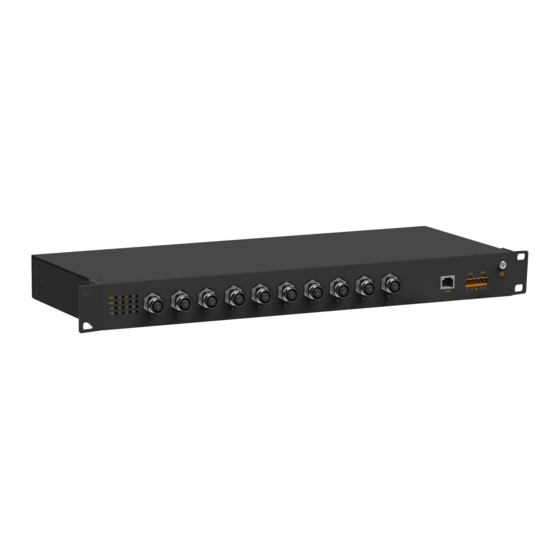
Page 7: Structure And Interface
2 Structure and Interface Caution: It is recommended to purchase the port dustproof shield (optional) to keep ports clean and ensure switch performance. (11) (5)(6) (10) (11) (10) Figure 1 Front Panel (1) Running LED (2) Ring LED (3) Power 1 LED (4) Power 2 LED (5) 10/100Base-T(X) Ethernet port connection status LED (6) 10/100/1000Base-T(X) Ethernet port connection status LED... -
Page 8: Mounting
3 Mounting 3.1 Dimension Drawing 465.4 Figure 2 Dimensions(unit: mm) Caution: As part of the heat dissipation system, the switch housing becomes ● hot during operation. Please use caution when coming in contact and avoid covering the switch housing when the switch is running. The figures in this manual are only for reference. - Page 9 Installing Mounting Brackets ● Screw holes for securing the mounting bracket to a switch Screw holes for securing the mounting bracket to a rack post Figure 3 Mounting Bracket You can install the mounting brackets through the screw holes for front panel mounting.
-
Page 10: Connection
Mounting ● Step 1: Select the mounting position for the switch and guarantee adequate space and heat dissipation. Step 2: Move the switch in direction 1 until the screw holes for securing the mounting brackets to rack posts are in alignment with the corresponding holes in the rack posts. - Page 11 Pin Definition ● Figure 6 M12 Port (female) Figure 7 RJ45 Port You can use an M12-M12 or M12-RJ45 cable to connect the port for communication. The preceding figures show the pin numbers of an M12 port and an RJ45 port. For pin definitions, see the following table.
-
Page 12: 10/100/1000Base-T(X) Ethernet Port
Wiring Sequence ● Facing the B Facing the A direction direction Straight-through cable M12 RJ45 Orange and White Green and White Orange Green Cross-over cable Green and White Orange and White Green Orange Figure 8 Connection Using Straight-through/Cross-over Cable Note: The color of the cable for RJ45 connector meets the 568B standard: ●... - Page 13 Pin Definition ● Figure 9 M12 Port (female) Figure 10 RJ45 Port You can use an M12-M12 or M12-RJ45 cable to connect the port for communication. The preceding figures show the pin numbers of an M12 port and an RJ45 port. For pin definitions, see the following table.
- Page 14 Wiring Sequence ● Facing the B Facing the A direction direction Straight-through cable M12 RJ45 M12 RJ45 Cross-over cable Figure 11 Connection Using Straight-through/Cross-over Cable Note: The color of the cable for RJ45 connector meets the 568B standard: 1-orange and white, 2-orange, 3-green and white, 4-blue, 5-blue and white, 6-green, 7-brown and white, and 8-brown.
-
Page 15: Console Port
4.3 Console Port There is a Console port on the front panel of the switch. Connect the 9-pin serial port of a PC to the console port of the switch with a DB9- RJ45 console cable. You can configure, maintain, and manage the switch by running Hyper Terminal in the Windows OS of a computer. -
Page 16: Grounding
4.4 Grounding Grounding protects the device from lightning and interference. Therefore, you must ground the device properly.You need to ground the device before it is powered on and disconnect the grounding cable after the device is powered off. There is a grounding screw (see Figure 1) on the front panel of the device. The screw is for chassis grounding. - Page 17 Table 6 Pin Definitions of 5-Pin 5.08mm-Spacing Plug-in Terminal Block Wiring and Mounting ● Step 1: Ground the device properly according to section 4.4. Step 2: Remove the power terminal block from the switch. Step 3: Insert the power cable into the power terminal block according to Table 6 to fix the power cable.
-
Page 18: Leds
5 LEDs Table 8 LEDs 6 Switch Access You can access the switch in any of the following ways. 6.1 Access through Console Port Step 1: Connect the console port of the switch to the 9-pin serial port of a PC with the DB9-RJ45 console cable. - Page 19 Figure 15 Creating a Connection Step 4: Connect the communication port in use, as shown in the following figure. Figure 16 Selecting a Serial Port Note: To confirm the communication port in use, right-click [My Computer] and select [Property]. Click [Hardware] → [Device Manager] → [Port] to view the communication port.
- Page 20 Step 5: Set port parameters (Bits per second: 115200, Data bits: 8, Parity: None, Stop bits: 1 and Flow control: None), as shown in the following figure. Figure 17 Setting Port Parameters Step 6: Click OK to enter the switch CLI. Then you can run the commands in Table 9 and Table 10 to perform operations.
-
Page 21: Access Through Telnet
Step 2: On the Windows desktop, click Start and Run. The Run Dialog box is displayed. Enter "telnet IP-address”. For example, if the IP address of the switch is 192.168.0.2 (default IP address of a Kyland switch), enter "telnet 192.168.0.2" in the dialog box. -
Page 22: Access Through Web
6.3 Access through Web Step 1: Connect the network port of the PC to the Ethernet port of the device with a network cable. Step 2: Enter the IP address of the switch in the address box of the browser. The user login interface is displayed.
Need help?
Do you have a question about the Aquam8012A-1U Series and is the answer not in the manual?
Questions and answers