
Related Manuals for KYLAND SICOM6432G Series


Summary of Contents for KYLAND SICOM6432G Series
- Page 1 SICOM6432G/3432G Series Industrial Ethernet Switches Hardware Installation Manual Publication Date: Apr. 2020 Version: V1.0 No.: 112020177...
- Page 2 SICOM6432G/3432G Series Industrial Ethernet Switches Hardware Installation Manual Disclaimer: Kyland Technology Co., Ltd. tries to keep the content of this manual as accurate and as updated as possible. This document is not guaranteed to be error-free, and we reserve the right to amend it without notice to users.
- Page 3 Before using the device, read this manual carefully for personal and equipment safety. Please keep the manual for further reference. Kyland is not liable to any personal or equipment damage caused by violation of this notice.
- Page 4 Dispose of the device in accordance with relevant national provisions, preventing environmental pollution. In the following cases, please immediately shut down your power supply and contact your Kyland representative: Water gets into the equipment. Equipment damage or shell damage.
-
Page 5: Table Of Contents
Contents 1 Product Overview ......................1 2 Structure and Interface ...................... 4 3 Mounting ..........................5 3.1 Dimension Drawing ..................... 5 3.2 Mounting Modes and Steps ..................6 4 Connection ........................8 4.1 10/100/1000Base-T(X) Ethernet Port ................8 4.2 1000Base-X, 10/100/1000Base-T(X) SFP slot ............9 4.2.1 Gigabit SFP Optical Module ................ -
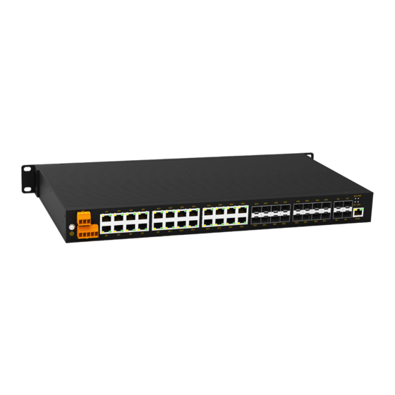
Page 6: Product Overview
1 Product Overview SICOM6432G/3432G include a series of high-performance 10 Gigabit industrial Ethernet switches developed by Kyland particularly. The solid closed housing, fanless but heat dissipation-capable chassis, overcurrent, overvoltage protection for power input, and IP65 protection class, make this series of device widely used in coal industry, factory automation, highway system and other fields. - Page 7 Product Overview 4X24GE: four 10GBase-X SFP+; twenty-four 10/100/1000Base-T(X) ports PS1: power input 1 L2(24-48VDC)、HV (220AC/DCW) PS2: power input 2 L2(24-48VDC)、HV (220AC/DCW)、NA Table 2 SICOM3432G Models Model SICOM3432G-PORT-PS1-PS2 Code definition Code option 4X8G8GX16GE, 8G8GX16GE, 4GX24GE, 4X24GE Note: : 4X8G8GX16GE ; four 10GBase-X SFP+ ;...
- Page 8 Product Overview Note: We reserve the right to amend the product information listed in this table without notice. To obtain the latest information, you can contact our sales or technical support personnel.
-
Page 9: Structure And Interface
Structure and Interface 2 Structure and Interface Caution: It is recommended to purchase the port dustproof shield (optional) to keep ports clean and ensure switch performance. (12) (1)(2) (11) (10) Figure 1 Front Panel Table 3 Description of the Front Panel Identifier Description Alarm... -
Page 10: Mounting
Mounting 3 Mounting 3.1 Dimension Drawing Figure 2 SICOM6432G&3432G Dimensions (unit: mm) Caution: As part of the heat dissipation system, the switch housing becomes hot during operation. Please use caution when coming in contact and avoid covering the switch housing when the switch is running. -
Page 11: Mounting Modes And Steps
Mounting 3.2 Mounting Modes and Steps The series switches support rack mounting by front/rear panel. The following uses mounting by front panel as an example to describe mounting steps. The steps for mounting by rear panel are similar to those for mounting by front panel. Before installation, make sure that the following requirements are met. - Page 12 Mounting You can select the screw holes for front or rear panel mounting to install the mounting brackets. If there are screws inserted in the screw holes, remove the screws and keep them for future use. As shown in the following figure, use four screws to secure two mounting brackets to the switch respectively.
-
Page 13: Connection
Connection 4 Connection 4.1 10/100/1000Base-T(X) Ethernet Port 10/100/1000Base-T(X) Ethernet port is equipped with RJ45 connector. The port is self-adaptive. It can automatically configure itself to work in 10M, 100M, or 1000M state, full or half duplex mode. The port can also adapt to MDI or MDI-X connection automatically. You can connect the port to a terminal or network device with a straight-through or cross-over cable. -
Page 14: 1000Base-X, 10/100/1000Base-T(X) Sfp Slot
Connection Figure 6 Connection Using Straight-through/Cross-over Cable Note: The color of the cable for RJ45 connector meets the 568B standard: 1-orange and white, 2-orange, 3-green and white, 4-blue, 5-blue and white, 6-green, 7-brown and white, and 8-brown. 4.2 1000Base-X, 10/100/1000Base-T(X) SFP slot 1000Base-X, 10/100/1000Base-T(X) SFP slot (gigabit SFP slot) requires an SFP optical/electrical module to enable data transmission. -
Page 15: Gigabit Sfp Optical Module
Connection 4.2.1 Gigabit SFP Optical Module Figure 7 Gigabit SFP Optical Module An SFP optical module is equipped with LC connector, and each port consists of a TX (transmit) port and an RX (receive) port. To enable communication between Device A and Device B, connect the TX port of Device A to the RX port of Device B, and the RX port of Device A to the TX port of Device B, as shown in the following figure. -
Page 16: Gigabit Sfp Electrical Module
Connection If the LED is on, the connection is correct. If the LED is off, the link is not connected. This may be caused by incorrect connection of the TX and RX ports. In this case, swop the two connectors at one end of the fibers. Caution: ... -
Page 17: 10Gbase-X Sfp+ Port
Connection 10/100/1000Base-T(X) Ethernet port. Plug the optical fiber and the twisted pair into GX and GE respectively; GX can communicate normally and the GE will be disabled automatically. The following table lists the relation of Gigabit SFP ports of Combo port and the corresponding 10/100/1000 Base-T(X) Ethernet port. -
Page 18: Console Port
Connection 4.5 Console Port There is a Console port on the front panel of the switch. This console port is an RJ45 interface. You can configure, maintain, and manage the device in two ways. Way1: Connect the 9-pin serial port of a PC to the console port of the switch with a DB9-RJ45 console cable. -
Page 19: Grounding
Connection RXD (Receive data) TXD (Transmit data) TXD (Transmit data) RXD (Receive data) GND (Grounding) GND (Grounding) Way2: Use a standard RJ45 network cable to connect the network port of the PC and the console port of the device, and configure and manage the device through the web. 4.6 Grounding Grounding protects the device from lightning and interference. - Page 20 Connection Figure 14 5-Pin 5.08mm-Spacing Plug-in Terminal Block Table 9 Pin Definitions of 5-Pin 5.08mm-Spacing Plug-in Terminal Block Signal DC Definition AC Definition PWR1: + PWR1: L PWR1: - PWR1: N PGND PGND PWR2: - PWR2: N PWR2: + PWR2: L Caution: For single power supply, only pins 1, 2, and 3 (PWR1) of the terminal block can be connected.
-
Page 21: Alarm Terminal Block
Connection Warning: Do not touch any exposed conducting wire, terminal, or component with a voltage warning sign, because it may cause personal injury. Do not remove any part or plug in or out any connector when the device is powered on. 4.8 Alarm Terminal Block The alarm terminal block is used for alarm output. -
Page 22: Leds
LEDs 5 LEDs Table 10 Front Panel LEDs State Description The power 1 is connected and operates properly. Power 1 LED-PWR1 The power 1 is not connected or operates abnormally. The power 2 is connected and operates properly. Power 2 LED-PWR2 The power 2 is not connected or operates abnormally. - Page 23 LEDs Effective port connection 10GBase-X SFP+ slot connection Blinking Ongoing network activities status LED No effective port connection...
-
Page 24: Switch Access
Switch Access 6 Switch Access You can access the switch in any of the following ways: 6.1 Access through Console Port The console port is an RJ45 interface, and you can access the device in two ways. DB9-RJ45 console cable Step 1: Connect the console port of the switch to the 9-pin serial port of a PC with the delivered DB9-RJ45 console cable. - Page 25 Switch Access Figure 17 Selecting the Communication Port in Use Note: To confirm the communication port in use, right-click [My Computer] and click [Property]→ [Hardware]→[Device Manager]→[Port] to view the communication port. Step 5: Set port parameters (Bits per second: 115200, Data bits: 8, Parity: None, Stop bits: 1, and Flow control: None), as shown in Figure 18.
-
Page 26: Access Through Telnet
Step 1: Connect the network port of a PC to the Ethernet port of the switch with a network cable. Step 2: Enter "telnet IP-address" in the Run dialog box, as shown in Figure 19. The default IP address of a Kyland switch is 192.168.0.2. -
Page 27: Access Through Web
Switch Access Figure 19 Access through Telnet Step 3: Click OK. The Telnet CLI is displayed. Then you can enter commands (as shown in Table 11) to perform operations. 6.3 Access through Web Step 1: Connect the network port of a PC to the Ethernet port of the switch with a network cable. -
Page 28: Basic Features And Specifications
Basic Features and Specifications 7 Basic Features and Specifications Power Requirements Power Identifier Rated Voltage Range Maximum Voltage Range 24-48VDC 18-72VDC HV (220AC/DCW) 100-240VAC,50/60Hz;110-220VDC 85-264VAC/77-300VDC Terminal Block 5-pin 5.08mm spacing terminal block Rated Power Consumption Rated Power 53.9W(MAX) Consumption Physical Characteristics Housing: Metal, fanless Installation... - Page 29 FAX: +86-10-88796678 Website: http://www.kyland.com Email: support@kyland.com For more information about KYLAND products, please visit our website: http://www.kyland.com...
Need help?
Do you have a question about the SICOM6432G Series and is the answer not in the manual?
Questions and answers