
Related Manuals for KYLAND SICOM3024


Summary of Contents for KYLAND SICOM3024
- Page 1 SICOM3024 Industrial Ethernet Switch Hardware Installation Manual Publication Data: May 2013 Version: V1.0 No.: 1.12.02.0118-0...
- Page 2 SICOM3024 Industrial Ethernet Switch Hardware Installation Manual Disclaimer: Kyland Technology Co., Ltd. tries to keep the content of this manual as accurate and as updated as possible. This document is not guaranteed to be error-free, and we reserve the right to amend it without notice to users.
- Page 3 Before using the device, read this notice carefully for personal and equipment safety. Please keep the manual for further reference. Kyland is not liable to any personal or equipment damage caused by violation of this notice.
- Page 4 ● Dispose of the device in accordance with relevant national provisions, preventing environmental pollution. In the following cases, please immediately shut down your power supply and contact your Kyland represen- tative: ● Water gets into the equipment. ● Equipment damage or shell damage.
-
Page 5: Table Of Contents
Contents 1 Product Overview………………………………………………………1 2 Structure and Interface………………………………………………2 2.1 Front Panel…………………………………………………………2 2.2 Rear Panel…………………………………………………………4 3 Mounting……………………………………………………………… 6 3.1 Dimension Drawing………………………………………………6 3.2 Mounting Modes and Steps……………………………………7 4 Connection……………………………………………………………10 4.1 10/100Base-T(X) Ethernet Port………………………………10 4.2 100Base-FX Ethernet Port……………………………………12 4.3 1000Base-X, 10/100/1000Base-T(X) SFP Slot… … … … … 13 4.3.1 Gigabit SFP Optical Module………………………………14 4.3.2 Gigabit SFP Electrical Module……………………………16 4.4 Console Port……………………………………………………17... -
Page 6: Product Overview
CLI, Telnet, Web, Kyvision, and SNMP- based network management software. SICOM3024 supports 19 inch 1U rack mounting. It provides up to four 1000Base-X, 10/100/1000Base-T(X) SFP slots (gigabit SFP slots), eight fiber or copper (optional)100M Ethernet ports, and sixteen 10/100Base-T(X) Ethernet ports, as listed in the following table. -
Page 7: Structure And Interface
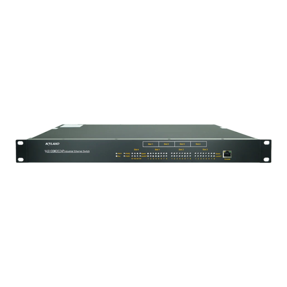
Structure and Interface 2 Structure and Interface Caution: To keep ports clean and ensure switch performance, you are advised to purchase the port dustproof shield (optional). 2.1 Front Panel (1)(3) (2)(4) (6) Figure 1 Front Panel of SICOM3024... - Page 8 Structure and Interface Table 2 Description of the Front Panel of SICOM3024...
-
Page 9: Rear Panel
Structure and Interface 2.2 Rear Panel Slot 1 Slot 2 Slot 3 Slot 4 (1) (2) (5)(6)(7) (11) (11) (9)(10) (11) (11) Figure 2 Rear Panel of SICOM3024... - Page 10 Structure and Interface Table 3 Description of the Rear Panel of SICOM3024 Caution: The figure above shows the rear panel of SICOM3024. The ● layout of slot1, slot2, and slot3 is fixed and that of slot4 can be A, B, C, D, or E. The actual layout depends on the models you select.
-
Page 11: Mounting
Mounting 3 Mounting 3.1 Dimension Drawing 482.6 Figure 3 Dimension Drawing (unit: mm) Caution: As part of the heat dissipation system, the switch housing ● becomes hot during operation. Please use caution when coming in contact and avoid covering the switch housing when the switch is running. -
Page 12: Mounting Modes And Steps
Mounting 3.2 Mounting Modes and Steps The series switches support rack mounting by the front/rear panel. The following uses mounting by front panel as an example to describe mounting steps. The steps for mounting by rear panel are similar to those for mounting by front panel. Before installation, make sure that the following requirements are met. - Page 13 Mounting You can select the screw holes for front or rear panel mounting to install the mounting brackets. If there are screws inserted in the screw holes, remove the screws and keep them for future use. As shown in the following figure, use three screws to secure two mounting brackets to the switch respectively.
- Page 14 Mounting Mounting ● Step 1: Select the mounting position for the switch and guarantee adequate space and heat dissipation (dimensions: 440mm× 44mm×245mm). Step 2: Move the switch in direction 1 until the screw holes for securing the mounting brackets to rack posts are in alignment with the corresponding holes in the rack posts.
-
Page 15: Connection
Connection 4 Connection 4.1 10/100Base-T(X) Ethernet Port 10/100Base-T(X) Ethernet port is equipped with RJ45 connector. The port is self-adaptive. It can automatically configure itself to work in 10M or 100M state, full or half duplex mode. The port can also adapt to MDI or MDI-X connection automatically. - Page 16 Connection Wiring Sequence ● RJ45 connector RJ45 connector Straight-through cable Wiring sequence Cross-over cable Wiring sequence Figure 8 Connection Using Straight-through/Cross-over Cable Note: The color of the cable for RJ45 connector meets the 568B standard: 1-orange and white, 2-orange, 3-green and white, 4-blue, 5-blue and white, 6-green, 7-brown and white, and 8-brown.
-
Page 17: 100Base-Fx Ethernet Port
Connection 4.2 100Base-FX Ethernet Port 100Base-FX Ethernet port is equipped with FC/ST/SC connector, and each port consists of TX (transmit) port and RX (receive) port. To enable data transmission between Device A and Device B, connect the TX port of Device A to the RX port of Device B, and the RX port of Device A to the TX port of Device B. -
Page 18: 1000Base-X, 10/100/1000Base-T(X) Sfp Slot
Connection 4.3 1000Base-X, 10/100/1000Base-T(X) SFP Slot 1000Base-X, 10/100/1000Base-T(X) SFP slot (gigabit SFP slot) requires an SFP optical/electrical module to enable data transmis- sion. The following table lists the gigabit SFP optical/electrical modules (optional) supported by the series switches. Table 5 Gigabit SFP Optical/Electrical Modules... -
Page 19: Gigabit Sfp Optical Module
Connection 4.3.1 Gigabit SFP Optical Module Figure 10 Gigabit SFP Optical Module An SFP optical module is equipped with LC connector, and each port consists of a TX (transmit) port and an RX (receive) port. To enable communication between Device A and Device B, connect the TX port of Device A to the RX port of Device B, and the RX port of Device A to the TX port of Device B, as shown in the following figure. - Page 20 Connection How to Connect the SFP Optical Module ● Insert the SFP optical module into the SFP slot in the switch, and then insert the fibers into the TX port and RX port of the SFP module. SFP slot SFP optical module Optical fiber Figure 12 Connecting the SFP Optical Module Identify the RX port and TX port of an SFP optical module:...
-
Page 21: Gigabit Sfp Electrical Module
Connection 4.3.2 Gigabit SFP Electrical Module Figure 13 Gigabit SFP Electrical Module How to Connect the SFP Electrical Module ● Insert the SFP electrical module into the SFP slot in the switch, and then insert the RJ45 connector of the twisted pair into the SFP module. SFP slot SFP Electrical module RJ45 connector... -
Page 22: Console Port
Connection 4.4 Console Port SICOM3024 provides a console port on the front panel. Connect the 9-pin serial port of a PC to the console port of the switch with a DB9- RJ45 console cable. Then you can configure, maintain, and manage the switch by running Hyper Terminal in Windows OS of a computer. -
Page 23: Grounding
Connection Table 6 Pin Definitions of DB9 Port (9-Pin Serial Port) and RJ45 Port (Console Port) DB9 Port (9-Pin Serial Port) RJ45 Port (Console Port) Signal Signal RXD (Receive data) TXD (Transmit data) TXD (Transmit data) RXD (Receive data) GND (Grounding) GND (Grounding) 4.5 Grounding Grounding protects the switch from lightning and interference. -
Page 24: Power Terminal Block
Connection 4.6 Power Terminal Block There is a power terminal block on the rear panel of the device. You need to connect the power wires to the terminal block to provide power to the device. The device supports single (PWR1) and redun- dant (PWR1 and PWR2) power supply with a 5-pin 5.08mm-spacing plug-in terminal block. - Page 25 Connection The following table lists the pin definitions of the 5-pin 5.08mm-spacing plug-in terminal block. Table 7 Pin Definitions of 5-Pin 5.08mm-Spacing Plug-in Terminal Block Signal DC Definition AC Definition PWR1: + PWR1: L PWR1: - PWR1: N PGND PGND PWR2: - PWR2: N PWR2: +...
-
Page 26: Alarm Terminal Block
Connection PWR2:-/N PGND PWR1:-/N PWR2:+/L PWR1:+/L Plug Socket Figure 19 Connection of 5-Pin 5.08mm-Spacing Plug-in Terminal Block Caution: The switch supports 24DC, 48DC, and 220AC/DCW power input. Before connecting the device to power supply, make sure that the power input meets the power requirement. If connected to an incorrect power input, the device may be damaged. - Page 27 Connection 1 2 3 FAULT Figure 20 Alarm Terminal Block (socket) Electrical parameters of the relay: Max Switch Voltage: 250VAC/220VDC; Max Switch Current: 2A Max Switching Power: 60W Dielectric Strength: 2KV Note: Pin 1 and pin 2 are normally-open contacts; pin 2 and pin 3 are normally-closed contacts.
-
Page 28: Leds
LEDs 5 LEDs Table 8 Front Panel LEDs... - Page 29 LEDs Table 9 Rear Panel LEDs Speed(yellow) Connection status (green) Speed(yellow) Connection status (green) LED 1 and LED 2 indicate the status of the lower gigabit SFP slot, while LED 3 and LED 4 indicate the status of the upper gigabit SFP slot.
-
Page 30: Switch Access
Switch Access 6 Switch Access You can access the switch in any of the following ways: 6.1 Access through Console Port Step 1: Connect the console port of the switch to the 9-pin serial port of a PC with the delivered DB9-RJ45 console cable. Step 2: Open Hyper Terminal in Windows OS. - Page 31 Switch Access Step 4: Connect the communication port in use, as shown in the following figure. Figure 22 Selecting a Serial Port Note: To confirm the communication port in use, right-click [My Computer] and select [Property]. Click [Hardware] → [Device Manager] →...
- Page 32 Switch Access Step 5: Set port parameters (Bits per second: 9600, Data bits: 8, Parity: None, Stop bits: 1, and Flow control: None), as shown in the following figure. Figure 23 Setting Port Parameters Step 6: Click OK to enter the switch CLI. Then the following commands can be used to perform operations.
-
Page 33: Access Through Telnet
Switch Access 6.2 Access through Telnet Step 1:Connect the network port of a PC to the Ethernet port of the switch with a network cable. Step 2:On the Windows desktop, click Start and Run. The Run dialog box is displayed. Enter "telnet IP address". For example, if the IP address of the device is 192.168.0.2 (default IP address of the device), enter "telnet 192.168.0.2"... -
Page 34: Basic Features And Specifications
Basic Features and Specifications 7 Basic Features and Specifications... - Page 36 FAX: +86-10-88796678 Website: http://www.kyland.com Email: support@kyland.com For more information about KYLAND products, please visit our website: http://www.kyland.com...
Need help?
Do you have a question about the SICOM3024 and is the answer not in the manual?
Questions and answers