
Related Manuals for KYLAND SICOM6800 Series


Summary of Contents for KYLAND SICOM6800 Series
- Page 1 SICOM6800 Series Industrial Ethernet Switches Hardware Installation Manual Publication Date: Mar. 2024 Version: V1.0 No.:...
- Page 2 SICOM6800 Series Industrial Ethernet Switches Hardware Installation Manual Disclaimer: Kyland Technology Co., Ltd. tries to keep the content of this manual as accurate and as updated as possible. This document is not guaranteed to be error-free, and we reserve the right to amend it without notice to users.
- Page 3 Before using the device, read this manual carefully for personal and equipment safety. Please keep the manual for further reference. Kyland is not liable to any personal or equipment damage caused by violation of this notice.
- Page 4 Dispose of the device in accordance with relevant national provisions, preventing environmental pollution. In the following cases, please immediately shut down your power supply and contact your Kyland representative: Water gets into the equipment. Equipment damage or shell damage.
-
Page 5: Table Of Contents
Contents 1 Product Overview ....................... 1 2 Structure and Interface ....................... 2 2.1 Front Panel ........................2 2.2 Rear Panel ........................3 3 Mounting ..........................5 3.1 Dimension Drawing ......................5 3.2 Mounting Modes and Steps ..................5 4 Connection ......................... 9 4.1 100Base-X SFP Slot ....................9 4.2 10/100/1000Base-T(X) Ethernet Port ................ -
Page 6: Product Overview
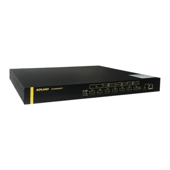
Product Overview 1 Product Overview SICOM6800 is a auto-controllable Layer3 rack mountable backbone network switch developed for occasions with high industrial control security requirements,using auto-controllable switching chips、physical layer chips 、CPUs and operating systems. The series switches support 19 inch 1U rack mounting by front/rear panel. It provides four 1000Base-X, SFP slots (Gigabit SFP Slot), and twenty-four 10/100/1000Base-T(X) Ethernet ports. -
Page 7: Structure And Interface
Switch Installation 2 Structure and Interface Caution: It is recommended to purchase the port dustproof shield (optional) to keep ports clean and ensure switch performance. 2.1 Front Panel 4GX24GE 4GX16SFP 16GX Figure 1 Front Panel Table 2 Description of Front Panel Identifier Description PWR1... -
Page 8: Rear Panel
Switch Installation PWR2 Power 2 LED Running LED Alarm Alarm LED Speed 10/100/1000Base-T(X) Ethernet Port speed LED Link/ACT 10/100/1000Base-T(X) Ethernet Port connection status LED Speed 1000Base-X SFP Port speed LED Link/ACT 1000Base-X SFP Port connection status LED Speed 100Base-X SFP slot speed LED (10) Link/ACT 100Base-X SFP slot connection status LED... - Page 9 Switch Installation Figure 2 Rear Panel Table 3 Description of Rear Panel Description Grounding screw Power terminal block Alarm terminal block 10/100/1000Base-T(X) Ethernet port 10/100/1000Base-T (X) Ethernet port speed LED (yellow) 10/100/1000Base-T (X) Ethernet port connection status LED (green) 100/1000M SFP 1000Base-X, SFP slot connection status LED (green, indicating the status of the upper slot) 1000Base-X, SFP slot speed LED (yellow, indicating the speed of the upper slot) (10)
-
Page 10: Mounting
Switch Installation 3 Mounting 3.1 Dimension Drawing Figure 3 Dimensions (unit: mm) Caution: As part of the heat dissipation system, the switch housing becomes hot during operation. Please use caution when coming in contact and avoid covering the switch housing when the switch is running. - Page 11 Switch Installation following requirements are met. 1) Environment: temperature (-40℃ to 75℃), ambient relative humidity (5% to 95%, non-condensing) 2) Power requirement: The power input is within the voltage range of the switch. 3) Grounding resistance: <5 4) No direct sunlight, distant from heat source and areas with strong electromagnetic interference.
- Page 12 Switch Installation Figure 2 Installing Mounting Brackets Mounting Step 1: Select the mounting position for the device and guarantee adequate space and heat dissipation for it (dimensions: 440mm×44mm×318.8mm). Step 2: Move the switch in direction 1 until the screw holes for securing the mounting brackets to rack posts are in alignment with the corresponding holes in the rack posts.
- Page 13 Switch Installation Step 2: Remove the switch from the rack posts. Then unscrew the mounting brackets to complete dismounting. Figure 4 Dismounting by Front Panel...
-
Page 14: Connection
Switch Installation 4 Connection 4.1 10/100/1000Base-T(X) Ethernet Port 10/100/1000Base-T(X) Ethernet port is equipped with RJ45 connector. The port is self-adaptive. It can automatically configure itself to work in 10M, 100M, or 1000M state, full or half duplex mode. The port can also adapt to MDI or MDI-X connection automatically. You can connect the port to a terminal or network device with a straight-through or cross-over cable. -
Page 15: 100Base-X Sfp Slot
Switch Installation Wiring Sequence Figure 5 Connection Using Straight-through/Cross-over Cable Note: The color of the cable for RJ45 connector meets the 568B standard: 1-orange and white, 2-orange, 3-green and white, 4-blue, 5-blue and white, 6-green, 7-brown and white, and 8-brown. -
Page 16: Gigabit Sfp Optical Module
Switch Installation transmission. The following table lists the gigabit SFP optical modules (optional) supported by the series switches. Table 6 Gigabit SFP Optical Modules Central Transmission Model Port MM/SM Connector Wavelength Distance IGSFP-M-SX-LC-850-0.55 1000Base-X port 850nm 0.55km IGSFP-S-LX-LC-1310-10 1000Base-X port 1310nm 10km IGSFP-S-LH-LC-1310-40... -
Page 17: Console Port
Switch Installation Figure 8 Connecting the SFP Optical Module Identify the RX port and TX port of an SFP optical module: 1. Insert the two connectors in one end of two fibers into the SFP module, and those in the other end into the peer module. - Page 18 Switch Installation Figure 9 Console Port DB9-RJ45 Console Cable One end of a DB9-RJ45 console cable is the DB9 connector to be inserted into the 9-pin serial port of a PC, and the other end is crimped RJ45 connector to be inserted into the console port of the switch.
-
Page 19: Grounding
Switch Installation Use a standard RJ45 network cable to connect the network port of the PC and the console port of the device, and configure and manage the device through the web. 4.5 Grounding Grounding protects the device from lightning and interference. Therefore, you must ground the device properly. - Page 20 Switch Installation Figure 11 5-Pin 5.08mm-Spacing Plug-in Terminal Block Table 8 Pin Definitions of 5-Pin 5.08mm-Spacing Plug-in Terminal Block Signal DC Definition AC Definition PGND PGND PWR1+ DC1:+ AC1:L PWR1- DC1:- AC1:N PWR2+ DC2:- AC2:N PWR2- DC2:+ AC2:L Caution: For single power supply, only pins 1, 2, and 3 (PWR1) of the terminal block can be connected. Do not use pins 4 and 5.
-
Page 21: Alarm Terminal Block
Switch Installation Caution: Before connecting the device to power supply, make sure that the power input meets the power requirement. If connected to an incorrect power input, the device may be damaged. Warning: Do not touch any exposed conducting wire, terminal, or component with a voltage ... -
Page 22: Leds
Switch Installation 5 LEDs Table 9 Front Panel LEDs State Description The power 1 is connected and operates properly. Power 1 LED-PWR1 The power 1 is not connected or operates abnormally. The power 2 is connected and operates properly. Power 2 LED-PWR2 The power 2 is not connected or operates abnormally. - Page 23 Switch Installation 1000M working state (1000Base-T) 10/100/1000Base-T(X) RJ45 Port 10M or 100M working state (10/100Base-T(X) ) or speed LED no connection Table 10 Rear Panel LEDs State Description 1000M working state (1000Base-T) 10/100/1000Base-T(X) Ethernet port 10M or 100M working state (10/100Base-T(X) ) or speed LED (yellow) no connection Effective port connection...
-
Page 24: Switch Access
Switch Installation 6 Switch Access You can access the switch in any of the following ways: 6.1 Access through Console Port The console port is an RJ45 interface, and you can access the device in two ways. DB9-RJ45 console cable Step 1: Connect the console port of the switch to the 9-pin serial port of a PC with the delivered DB9-RJ45 console cable. - Page 25 Switch Installation Figure 13 Selecting the Communication Port in Use Note: To confirm the communication port in use, right-click [My Computer] and click [Property] → [Hardware]→[Device Manager]→[Port] to view the communication port. Step 5: Set port parameters (Bits per second: 115200, Data bits: 8, Parity: None, Stop bits: 1, and Flow control: None), as shown in Figure 14.
-
Page 26: Access Through Telnet
Step 1: Connect the network port of a PC to the Ethernet port of the switch with a network cable. Step 2: Enter "telnet IP-address" in the Run dialog box, as shown in Figure 15. The default IP address of a Kyland switch is 192.168.0.2. -
Page 27: Access Through Web
Switch Installation Figure 15 Access through Telnet Step 3: Click OK. The Telnet CLI is displayed. Then you can enter commands (as shown in Table 11) to perform operations. 6.3 Access through Web Step 1: Connect the network port of a PC to the Ethernet port of the switch with a network cable. -
Page 28: Basic Features And Specifications
Switch Installation 7 Basic Features and Specifications Power Requirements Power Identifier Rated Voltage Range Maximum Voltage Range 24-48VDC 18-72VDC HV (220AC/DCW) 100-240VAC,50/60Hz;110-220VDC 85-264VAC/77-300VDC Terminal Block 5-pin 5.08mm spacing terminal block Rated Power Consumption SICOM6800-4GX24GE:51W (Max) Rated Power SICOM6800-4GX16SFP:29W (Max) Consumption SICOM6800-16GX:31W (Max) Physical Characteristics Housing:... - Page 29 Switch Installation Warranty Five years...
- Page 30 FAX: +86-10-88796678 Website: http://www.kyland.com Email: support@kyland.com For more information about KYLAND products, please visit our website: http://www.kyland.com...
Need help?
Do you have a question about the SICOM6800 Series and is the answer not in the manual?
Questions and answers