
Related Manuals for KYLAND Aquam8112 Series


Summary of Contents for KYLAND Aquam8112 Series
- Page 1 Aquam8112/8612/8120/8620/8128/8628 Series Industrial Ethernet Switches Hardware Installation Manual Publication Date: Apr. 2021 Version: V1.2 No.: 112023104...
- Page 2 Aquam8112/8612/8120/8620/8128/8628 Series Industrial Ethernet Switches Hardware Installation Manual Disclaimer: Kyland Technology Co., Ltd. tries to keep the content of this manual as accurate and as updated as possible. This document is not guaranteed to be error-free, and we reserve the right to amend it without notice to users.
- Page 3 Before using the device, read this manual carefully for personal and equipment safety. Please keep the manual for further reference. Kyland is not liable to any personal or equipment damage caused by violation of this notice.
- Page 4 Dispose of the device in accordance with relevant national provisions, preventing environmental pollution. In the following cases, please immediately shut down your power supply and contact your Kyland representative: Water gets into the equipment. Equipment damage or shell damage.
-
Page 5: Table Of Contents
Contents 1 Product Overview ......................1 2 Structure and Interface ...................... 5 3 Mounting ..........................8 3.1 Dimension Drawing ..................... 8 3.2 Mounting Modes and Steps ..................10 4 Connection ........................12 4.1 10/100Base-T(X) Ethernet Port ..................12 4.1.1 Functions ......................12 4.1.2 Pin Definitions and Wiring Sequence ..............13 4.2 10/100/1000Base-T(X) Ethernet Port .................15 4.3 Console Port ......................17 4.4 Grounding ........................18... -
Page 6: Product Overview
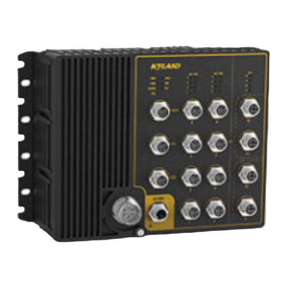
1 Product Overview Aquam8112/8612/8120/8620/8128/8628 includes a series of high-performance industrial Ethernet switches developed by Kyland particularly for rail transportation industry. The series devices are applicable to PIS, CCTV, video monitoring system, train control system, and the industrial field with strict requirements on vibration, shock, and EMC compatibility... - Page 7 Product Overview Aquam8612-NAT-PORT-PS1-PS2 Aquam8612-NAT-B-PORT-PS1-PS2 Aquam8612-NAT-B-PORT-PS1-PS2-ETBN Code definition Code option Support Bypass function Gigabit model support only) Hardware supports NAT function 8T,4GE8T,8P,4GE8P Note: 8T: eight 10/100Base-T(X) M12 ports. Ports: GE, T, P 4GE8T: four 10/100/1000Base-T(X) M12 ports; eight 10/100Base-T(X) M12 ports. 8P: eight 10/100Base-T(X) M12 POE ports.
- Page 8 Product Overview 16T,4GE16T,16P,4GE16P Note: 16T: sixteen 10/100Base-T(X) M12 ports. 4GE16T: four 10/100/1000Base-T(X) M12 ports; sixteen 10/100Base-T(X) M12 Ports: GE, T, P ports. 16P: sixteen 10/100Base-T(X) M12 POE ports. 4GE16P: four 10/100/1000Base-T(X) M12 ports; sixteen 10/100Base-T(X) M12 POE ports. PS1: power input 1 L2(24-48VDC)、H6(72-110VDC) PS2: power input 2 L2(24-48VDC)、H6(72-110VDC)
- Page 9 Product Overview 24P: twenty-four 10/100Base-T(X) M12 POE ports. 4GE24P: four 10/100/1000Base-T(X) M12 ports; twenty-four 10/100Base-T(X) M12 POE ports. PS1: power input 1 L2(24-48VDC)、H6(72-110VDC) PS2: power input 2 L2(24-48VDC)、H6(72-110VDC) ETBN TRDP,TTDP,TTDB functions Table 4 Optional Accessories Model Description Remarks Female cable connector with M23, Power interface Connector M23-A-5P-F-Crimp A-Coding, 5 Pin...
-
Page 10: Structure And Interface
Structure and Interface 2 Structure and Interface Caution: It is recommended to purchase the port dustproof shield (optional) to keep ports clean and ensure switch performance. (10)(11) (12) (13) (14) (15) (16) (17) - Page 11 Structure and Interface (9) (10)(11) (12) (13) (14) (15) (16) (17) (15) (9) (10) (11) (12) (13) (14) (16) (17) Figure 1 Front Panel External (1) Power 1 LED (2) Power 2 LED power LED (4) Ring LED (5) Alarm port (6) USB Port (7) Console port (8) Main Power port...
- Page 12 Structure and Interface (10) USB LED (11) Ring LED (12) 10/100Base-T(X) Ethernet port (13) 10/100Base-T(X) Ethernet port connection status LED (14) 10/100Base-T(X) Ethernet Port POE LED (15) 10/100/1000Base-T(X) Ethernet port connection status LED (16) 10/100/1000Base-T(X) Ethernet port (17) External Power Port* Note: ...
-
Page 13: Mounting
Mounting 3 Mounting 3.1 Dimension Drawing Figure 2 Aquam8112/8612 Series Dimensions (unit: mm) - Page 14 Mounting Figure 3 Aquam8120/8620 Series Dimensions (unit: mm) Figure 4 Aquam8128/8628 Series Dimensions (unit: mm)
-
Page 15: Mounting Modes And Steps
Mounting Caution: As part of the heat dissipation system, the switch housing becomes hot during operation. Please use caution when coming in contact and avoid covering the switch housing when the switch is running. The figures in this manual are only for reference. 3.2 Mounting Modes and Steps The series devices support panel mounting. - Page 16 Mounting Figure 5 Panel Mounting Dismounting Loosen the screws with a screwdriver, remove the screws and device from the wall or inner wall of a cabinet to complete dismounting.
-
Page 17: Connection
Connection 4 Connection 10/100Base-T(X) port connector, 10/100/1000Base-T(X) port connector, console port connector, USB port connector, power port connector, and external power port connection cable are all optional (For details, see Table 4 ). That is, these components need to be purchased separately as required. -
Page 18: Pin Definitions And Wiring Sequence
Connection 4.1.2 Pin Definitions and Wiring Sequence Pin Definition Figure 6 M12 Port (female) Figure 7 RJ45 Port You can use an M12-M12 or M12-RJ45 cable to connect the port for communication. The preceding figures show the pin numbers of an M12 port and an RJ45 port. For pin definitions, see the following table. - Page 19 Connection Note: "+" and "-" indicate level polarities. Wiring Sequence Figure 8 Connection Using Straight-through/Cross-over Cable Note: The color of the cable for RJ45 connector meets the 568B standard: 1-orange and white, 2-orange, 3-green and white, 4-blue, 5-blue and white, 6-green, 7-brown and white, and 8-brown.
-
Page 20: 10/100/1000Base-T(X) Ethernet Port
Connection PSE. 4.2 10/100/1000Base-T(X) Ethernet Port 10/100/1000Base-T(X) Ethernet port is equipped with M12 connector, which is dustproof, waterproof, and anti-vibration. The port is self-adaptive. It can automatically configure itself to work in 10M or 100M state, full or half duplex mode. The port can also adapt to MDI or MDI-X connection automatically. - Page 21 Connection Transmit/Receive Data (TRD3+) Transmit/Receive Data (TRD2+) Transmit/Receive Data (TRD3-) Transmit/Receive Data (TRD2-) Transmit/Receive Data (TRD2+) Transmit/Receive Data (TRD3+) Transmit/Receive Data (TRD2-) Transmit/Receive Data (TRD3-) RJ45 Port Transmit/Receive Data (TRD1+) Transmit/Receive Data (TRD0+) Transmit/Receive Data (TRD1-) Transmit/Receive Data (TRD0-) Transmit/Receive Data (TRD0+) Transmit/Receive Data (TRD1+) Transmit/Receive Data (TRD3+) Transmit/Receive Data (TRD2+)
-
Page 22: Console Port
Connection Figure 11 Connection Using Straight-through/Cross-over Cable Note: The color of the cable for RJ45 connector meets the 568B standard: 1-orange and white, 2-orange, 3-green and white, 4-blue, 5-blue and white, 6-green, 7-brown and white, and 8-brown. 4.3 Console Port There is a console port on the front panel. -
Page 23: Grounding
Connection Figure 12 Console Port (female) M12-DB9 Console Cable One end of the M12-DB9 cable is an M12 connector to be inserted into the console port of the device, and the other end is the DB9 connector to be inserted into the 9-pin serial port of a PC. -
Page 24: Power Port
Connection the grounding cable after the device is powered off. There is a grounding screw (see (15) (9) (10) (11) (12) (13) (14) (16) (17) ) on the front panel of the device. The screw is for chassis grounding. After crimping Figure 1 one end of the grounding cable to a cold pressed terminal, secure the end of the grounding cable to the grounding screw and firmly connect the other end to ground. - Page 25 Connection Figure 14 Main Power Port (male) Table 8 Pin Definitions of Power Port DC Wiring Definition PWR1:+ PWR1:- PGND PWR2:- PWR2:+ Wiring and Mounting Step 1: Ground the device properly according to section 4.4. Step 2: Insert one end of the power cable into the M23 connector firmly. Step 3: Insert the M23 connector with the connected cable into the power port on the device.
-
Page 26: Alarm Port
Connection 4.6 Alarm Port The device provides an alarm terminal block on the front panel for alarm output. When the switch works properly, the normally-open contacts of the alarm relay are closed and the normally-closed contacts are open; when an alarm occurs, the normally-open contacts are open and the normally-closed contacts are closed. -
Page 27: Bypass Port
Connection Step 2: Secure the four wires for alarm into the alarm terminal block in the required sequence. Step 3: Insert the alarm terminal block into its socket. 4.7 Bypass Port The series switches can provide two pairs of Bypass ports, as shown in Figure 16, Gigabit port 11 and port 12 are one pair of Bypass ports. -
Page 28: External Power Port
Connection Figure 17 M12 Port (female) Table 10 Pin Definitions of M12 Port Signal You can run the commands in Table 11 to perform operations. Table 11 CLI Commands for the device View Command Description Enable the U disk to automatically load the SWITCH#usb auto General mode SWITCH#save... - Page 29 Connection equipped with 4 Pin M12 connector. Additional 120W can be increased by adding isolated external power supply. Note: For devices that only support POE, there is an external power port. Non-POE models do not have this interface. POWER- POWER+ POWER+ POWER- Figure 18 External Power Port (male)
- Page 30 Connection Warning: Do not touch any exposed conducting wire, terminal, or component with a voltage warning sign, because it may cause personal injury. Do not remove any part or plug in or out any connector when the device is powered on.
-
Page 31: Leds
LEDs 5 LEDs Table 13 Front Panel LEDs State Description The power 1 is connected and operates properly. Power 1 LED-PWR1 The power 1 is not connected or operates abnormally. The power 2 is connected and operates properly. Power 2 LED-PWR2 The power 2 is not connected or operates abnormally. - Page 32 LEDs The POE port provides no power supply Note: external Non-POE products have no POE indicator and no power interface and indicator.
-
Page 33: Switch Access
Switch Access 6 Switch Access You can access the switch in any of the following ways. 6.1 Access through Console Port Step 1: Connect the console port of the switch to the 9-pin serial port of a PC with the M12-DB9 console cable. - Page 34 Switch Access Figure 20 Selecting a Serial Port Note: To confirm the communication port in use, right-click [My Computer] and select [Property]. Click [Hardware] → [Device Manager] → [Port] to view the communication port. Step 5: Set port parameters (Bits per second: 115200, Data bits: 8, Parity: None, Stop bits: 1 and Flow control: None), as shown in the following figure.
-
Page 35: Access Through Telnet
Switch Access Figure 21 Setting Port Parameters Step 6: Click OK to enter the switch CLI. Then you can run the commands in Table 14 to perform operations. Table 14 CLI Commands for the device View Command Description General mode SWITCH>enable Enter the privileged mode Privileged mode... -
Page 36: Access Through Web
Step 2: On the Windows desktop, click Start and Run. The Run Dialog box is displayed. Enter "telnet IP address”. For example, if the IP address of the switch is 192.168.0.2 (default IP address of a Kyland switch), enter "telnet 192.168.0.2" in the dialog box. Figure 22 Access through Telnet Step 3: Click OK. -
Page 37: Basic Features And Specifications
Basic Features and Specifications 7 Basic Features and Specifications Power Requirements Power Identifier Rated Voltage Range Maximum Voltage Range 24-48VDC 16.8-60VDC 72-110VDC 50.4-137.5VDC External Power 54.5VDC 54-57VDC Supply Main Power Supply: 5-pin M23 connector Terminal Block External Power Supply: 4-pin M12 connector Rated Power Consumption Aquam8112/8612 without POE: 24W (MAX) Aquam8112/8612 with POE: 174.1W (MAX) - Page 38 Basic Features and Specifications MAX 3.25A @ 48VDC MAX 2.38A @ 72VDC MAX 1.52A @ 110VDC Aquam8612-NAT without POE: MAX 1.01A @ 24VDC MAX 0.53A @ 48VDC MAX 0.36A @ 72VDC MAX 0.23A @ 110VDC Aquam8612-NAT with POE: MAX 6.78A @ 24VDC MAX 3.29A @ 48VDC MAX 2.41A @ 72VDC MAX 1.55A @ 110VDC...
- Page 39 Basic Features and Specifications MAX 0.78A @ 48VDC MAX 0.5A @ 72VDC MAX 0.35A @ 110VDC Aquam8128/8628 with POE: MAX 6.28A @ 24VDC MAX 3.19A @ 48VDC MAX 2.38A @ 72VDC MAX 1.67A @ 110VDC Aquam8628-NAT without POE: MAX 2.38A @ 24VDC MAX 0.81A @ 48VDC MAX 0.51A @ 72VDC MAX 0.34A @ 110VDC...
- Page 40 Basic Features and Specifications MTBF Aquam8112/8612:535254h MTBF Aquam8120/8620:602392h Aquam8128/8628:496657h Warranty Warranty Five years...
- Page 41 FAX: +86-10-88796678 Website: http://www.kyland.com Email: support@kyland.com For more information about KYLAND products, please visit our website: http://www.kyland.com...
Need help?
Do you have a question about the Aquam8112 Series and is the answer not in the manual?
Questions and answers