
Related Manuals for KYLAND Opal5G Series


Summary of Contents for KYLAND Opal5G Series
- Page 1 Opal5G/Opal10G Series Entry-Level Industrial Ethernet Switch Hardware Installation Manual Publication Date: Nov. 2018 Version: V1.3 No.: 112023038...
- Page 2 All rights reserved. No part of this documentation may be excerpted, reproduced, translated, annotated or duplicated, in any form or by any means without the prior written permission of Kyland Corporation. Copyright © 2018 Kyland Technology Co., Ltd.
- Page 3 Before using the device, read this notice carefully for personal and equipment safety. Please keep the manual for further reference. If the device used not according to the specified way by Kyland, the protection provided by the device maybe diminished. A Kyland is not liable to any personal or equipment damage caused by violation of this notice.
- Page 4 Note : The security of any system merged with this device is the responsibility of the assembler. In the following cases, please immediately shut down your power supply and contact your Kyland representative: Water gets into the equipment. Equipment damage or shell damage.
-
Page 5: Table Of Contents
Contents 1 Product Overview..........................2 2 Structure and Interface........................3 2.1 Front Panel..........................3 2.2 Top Panel...........................4 3 Mounting............................5 3.1 Dimension Drawing........................5 3.2 Mounting Modes and Steps....................6 3.2.1 DIN-Rail Mounting......................6 3.2.2 DIN-Rail Dismounting....................... 7 4 Connection............................8 4.1 10/100/1000Base-T(X) Ethernet Port..................8 4.2 1000Base-X SFP slot.......................9 4.3 Grounding.......................... -
Page 6: Product Overview
LV-LV=24VAC/DC (18-30VAC, 50/60Hz; 12-48VDC), redundant power input) input Note: We reserve the right to amend the product information listed in this table without notice. To obtain the latest information, you can contact our sales or technical support personnel. Kyland Opal5G/Opal10G IM-EN-June 2016... -
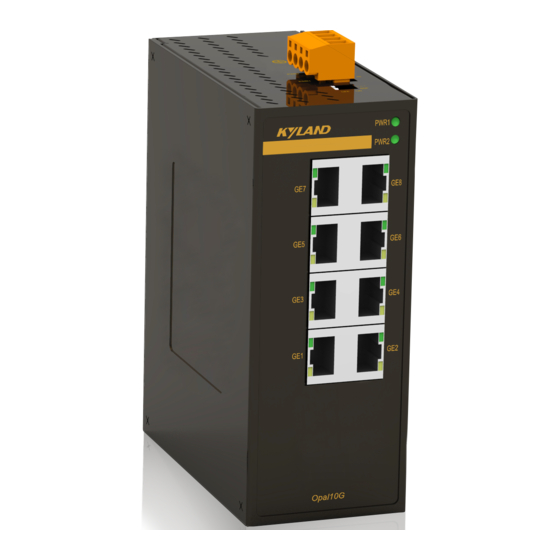
Page 7: Structure And Interface
(8) 1000Base-X SFP slot connection status LED (green, indicating the status of the left slot) (9) 1000Base-X SFP slot speed LED (yellow, indicating the speed of the right slot) (10) 1000Base-X SFP slot connection status LED (green, indicating the status of the right slot) Kyland Opal5G/Opal10G IM-EN-June 2016... -
Page 8: Top Panel
Structure and Interface 2.2 Top Panel Figure 2 Top Panel Kyland Opal5G/Opal10G IM-EN-June 2016... -
Page 9: Mounting
As part of the heat dissipation system, the switch housing becomes hot during operation. Please use caution when coming in contact and avoid covering the switch housing when the switch is running. The figures in this manual are only for reference. Kyland Opal5G/Opal10G IM-EN-June 2016... -
Page 10: Mounting Modes And Steps
Step 2: Insert the connecting seat onto the top of the DIN rail, and push the bottom of the device inward and upward to ensure the DIN rail fits in the connecting seat. Make sure the device is firmly installed on the DIN rail, as shown in the following figure. Figure 5 DIN-Rail Mounting Kyland Opal5G/Opal10G IM-EN-June 2016... -
Page 11: Din-Rail Dismounting
1 until the bottom of the device is detached from the DIN rail. Step 2: Pull the device upward and move the device in direction 2 until the device is removed from the DIN rail completely. Figure 6 DIN Rail Dismounting Kyland Opal5G/Opal10G IM-EN-June 2016... -
Page 12: Connection
Transmit/Receive Data (TRD3+) Transmit/Receive Data (TRD2+) Transmit/Receive Data (TRD3-) Transmit/Receive Data (TRD2-) Transmit/Receive Data (TRD0-) Transmit/Receive Data (TRD1-) Transmit/Receive Data (TRD2+) Transmit/Receive Data (TRD3+) Transmit/Receive Data (TRD2-) Transmit/Receive Data (TRD3-) Note: "+" and "-" indicate level polarities. Kyland Opal5G/Opal10G IM-EN-June 2016... -
Page 13: 1000Base-X Sfp Slot
Device B, connect the TX port of Device A to the RX port of Device B, and the RX port of Device A to the TX port of Device B, as shown in the following figure. Kyland Opal5G/Opal10G IM-EN-June 2016... - Page 14 If the defined transmission distance of an SFP module is longer than 60km, do not use a short fiber (<20km) for connection. If such a short fiber is used, the module will be burned. Kyland Opal5G/Opal10G IM-EN-June 2016...
-
Page 15: Grounding
The exposed power cable wires connecting the plug-in terminal block should be 3-5mm approximately. 4-Pin 5.08mm-Spacing Plug-in Terminal Block Figure 12 4-Pin 5.08mm-Spacing Plug-in Terminal Block (socket) Kyland Opal5G/Opal10G IM-EN-June 2016... - Page 16 Before connecting the device to power supply, make sure that the power input meets the power requirement. If connected to an incorrect power input, the device may be damaged. To comply with UL restrictions, this equipment must be powered from a source compliant with SELV. Kyland Opal5G/Opal10G IM-EN-June 2016...
-
Page 17: Dip Switches
State Description Enable broadcast storm protection Ⅰ Disable broadcast storm protection Transmit Jumbo frame. Ⅱ Drop Jumbo frame. Note: The length of Jumbo frame is 1518~10240 bytes for Opal5G; and that is 1518~9600 bytes for Opal10G. Kyland Opal5G/Opal10G IM-EN-June 2016... -
Page 18: Leds
SFP slot. 1000M working state (1000Base-X) 1000Base-X SFP slot speed LED (yellow) 100M working state (100Base-FX) or no connection Effective port connection 1000Base-X SFP slot connection Blinking Ongoing network activities status LED (green) No effective port connection Kyland Opal5G/Opal10G IM-EN-June 2016... -
Page 19: Basic Features And Specifications
-10℃ ≤ Tamb ≤ 60℃ Opal5G-E, Opal10G-E series Ambient Temperature -40℃ ≤ Tamb ≤ 75℃ Opal5G, Opal10G series Storage Temperature -40℃~+85℃ Ambient Relative Humidity 5%~95% (no condensing) Pollution degree Altitude 2000m MTBF Opal5G:3241152h MTBF Opal10G:2497305h Warranty Warranty Five years Kyland Opal5G/Opal10G IM-EN-June 2016... -
Page 20: Certificates Used For Compliance
Certificates Used for Compliance 7 Certificates Used for Compliance Certificates Approvals FCC 47CFR Part2 and part15 Class A Safety UL508/UL61010, Class1 Div2, ATEX/IECEx Kyland Opal5G/Opal10G IM-EN-June 2016... -
Page 21: Appendix
IP 54 in accordance with EN IEC/IEC 60079-0 and enclosure only accessible with tool removable cover. Transient protection shall be provided that is set at a level not exceeding 140 % of the peak rated voltage value at the supply terminals to the equipment. Kyland Opal5G/Opal10G IM-EN-June 2016... - Page 22 Kyland Technology Co., Ltd. FAX: +86-10-88796678 Website: http://www.kyland.com Email: support@kyland.com Factory Address: BUILDING NO.2, SHIXING AVENUE30#, SHIJINGSHAN DIST, BEIJING 100041 CHINA...
Need help?
Do you have a question about the Opal5G Series and is the answer not in the manual?
Questions and answers