Table of Contents
Advertisement
®
™
Bendix
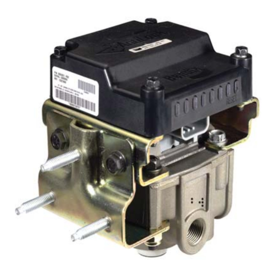
MC-30
Trailer ABS Controller Assembly
Delivery Ports
3/8" NPT (x4)
TABLE OF CONTENTS
Components . . . . . . . . . . . . . . . . . . . . . . .2
MC-30
™
™
Controller Assemblies. . . . . . . . . . . . . .2
™
Controller with PLC . . . . . . . . . . . . . . .2
Wiring Harness (Pigtail) . . . . . . . . . . . . . . . . .3
Power and Ground . . . . . . . . . . . . . . . . . . . .5
ABS Indicator Lamp . . . . . . . . . . . . . . . . . . .5
Wheel Speed Sensors . . . . . . . . . . . . . . . . . .5
™
ABS Modulator-Valves . . . . . . . . . . . . .6
J1708/J1587 Diagnostic Link . . . . . . . . . . . . . .6
Auxiliary I/O . . . . . . . . . . . . . . . . . . . . . . .6
™
Controller Power-up Sequence . . . . . . . . .7
ABS Operation . . . . . . . . . . . . . . . . . . . . . .7
Self-Confi guration/Control Toggle . . . . . . . . . . . .8
Other Confi gurable Parameters . . . . . . . . . . . . 11
Odometer Function. . . . . . . . . . . . . . . . . . . 11
Fault Detection . . . . . . . . . . . . . . . . . . . . . 11
™
Controller Diagnostic Display . . . . . . . . . 12
Blink Code Diagnostics . . . . . . . . . . . . . . . . 13
Bendix ABS Diagnostic Tools . . . . . . . . . . . . . 16
Contacting Bendix . . . . . . . . . . . . . . . . . . . 16
Correct Maintenance Practices . . . . . . . . . . . . 16
™
Servicing the MC-30
Controller . . . . . . . . . . . . 17
™
Overhaul of the Relay Valve . . . . . . . . . . . . . . 17
™
Reinstallation of the MC-30
™
Modulator-Valve . . . . . . . . . . . . . . . . 18
Leakage and Operational Tests . . . . . . . . . . . . 18
ABS Wiring . . . . . . . . . . . . . . . . . . . . . . . 18
Troubleshooting Flowcharts . . . . . . . . . . . . . . 24
Product Revision / Feature Introduction . . . . . . . . 32
For updates to this Service Data Sheet, please visit www.bendix.com.
LED Diagnostic
ABS Modulator
Connector
PAGE
™
Modulator. .2
Controller . . . . . . . . . . . 17
™
Display
(MOD1)
Supply Port
1/2" NPT
FIGURE 1 - MC-30
™
MC-30
CONTROLLER INTRODUCTION
™
The MC-30
controller is the Bendix antilock braking system
(ABS) controller assembly intended for application on air
braked heavy duty trailers, semi-trailers and dollies.
®
The Bendix
MC-30
diagnostic display with magnetic reset for easy diagnostics
and fault code clearing. Blink code diagnostics are standard
and advanced diagnostic tool support is also available.
The MC-30
™
controller supports PLC communication
for indicator lamp, full diagnostics capability and other
customized features.
The ABS function of the MC-30
provide a towed vehicle with improved stability and control
during braking while providing the maximum available
braking force.
Connector
1/4" NPT
™
CONTROLLER TANK (NIPPLE)
MOUNT ASSEMBLY
™
controller features an integral LED
™
controller is designed to
30-Pin
Control
Port
1
Advertisement
Table of Contents

Related Manuals for BENDIX MC-30 TRAILER ABS CONTROLLER


Summary of Contents for BENDIX MC-30 TRAILER ABS CONTROLLER
-
Page 1: Table Of Contents
Bendix ABS Diagnostic Tools ... . . 16 provide a towed vehicle with improved stability and control Contacting Bendix ....16 during braking while providing the maximum available Correct Maintenance Practices . -
Page 2: Components
™ FIGURE 2 - MC-30 CONTROLLER BRACKET (FRAME) ™ MC-12 modulator as the standard Bendix trailer ABS MOUNT ASSEMBLY controller assembly for OEM and aftermarket installations. ™ The EC-30T controller has a black plastic enclosure ™... -
Page 3: Wiring Harness (Pigtail)
For more information on these ™ EC-30T controller with a jackscrew tightened to 15-20 diagnostic tools, contact Bendix or refer to your local in. lbs. Improper tightening of the connector jackscrew authorized Bendix dealer. can cause environmental contamination or damage to the ™... -
Page 4: Power And Ground
Auxiliary I/O Connector POWER AND GROUND An optional auxiliary connector provides a connection to Trailer electrical power is supplied to the MC-30 ™ controller ™ the MC-30 controller auxiliary feature I/O pins. The fi ve ™ from the ignition and brake light circuits. Note: The MC-30 auxiliary ground-switch inputs and two auxiliary outputs can controller may not function properly when powered with a be activated and confi... -
Page 5: Power And Ground
™ controller to self-adjust. Proper sensor installation begins by fully from the Bendix wheel speed sensors. See Figure 8 for inserting the spring clip into the block, with the retaining examples. Working with a tone (exciter) ring, the wheel tabs toward the inside of the vehicle. See Figure 9. -
Page 6: M-30T Abs Modulator-Valves
™ performed using this link. The MC-30 controller is ® supported by diagnostic tools such as the MPSI Pro-Link ® and Bendix ABS Diagnostic Software. Ignition power must ™ be provided to the MC-30 controller for the diagnostic link ™... -
Page 7: Controller Power-Up Sequence
If a PLC tractor and PLC trailer are powered at the same ABS OPERATION time, the MC-30 ™ controller will also trigger a bulb check ™ The MC-30 controller uses wheel speed sensors, ABS on the tractor dash using PLC. modulator-valves and an ECU to control trailer wheels by axle or by side. -
Page 8: Self-Confi Guration/Control Toggle
Self-Confi guration Procedure SELF-CONFIGURATION / CONTROL TOGGLE When activated with a magnet or diagnostic tool, the Verify that the ECU, wheel speed sensor and ABS self-confi guration feature allows for wheel speed sensor, modulator connectors are in place and then power the modulator and ABS control settings to be altered. - Page 9 2S/1M Axle to 4S/2M Side to 2S/1M Axle 2S/1M Dolly-Axle Your dolly or steer axle has two Your trailer has two wheel speed wheel speed sensors and one ABS sensors and one ABS modulator that modulator that is plumbed for axle is plumbed for axle control.
- Page 10 4S/2M Side to 4S/2M Axle to 2S/2M Axle 2S/1M Dolly-Axle Your trailer has two wheel speed Your trailer has two wheel speed sensors and two ABS modulators sensors and two ABS modulators that are plumbed for side control. that are plumbed for axle control. ™...
-
Page 11: Other Confi Gurable Parameters
™ controller altered using a diagnostic tool. For further information, controls a trailer mounted indicator lamp to advise the driver contact Bendix or refer to your local authorized Bendix of the status of the system. The MC-30 ™ controller may dealer. -
Page 12: Controller Diagnostic Display
™ MC-30 CONTROLLER DIAGNOSTIC DISPLAY place. If one or more of the LEDs do not go on when the magnet is in place, replace the EC-30T ™ controller. When ™ The MC-30 controller diagnostic display consists of seven the magnet is removed from the reset location, only the red fault LEDs, one green power LED and an internal green VLT diagnostic LED should be on. -
Page 13: Blink Code Diagnostics
Fault history For more information on the Bendix ABS Diagnostic can be retrieved by using blink code diagnostics or a Software program, or RP-1210 compliant tools, contact diagnostic tool. Bendix or refer to your local authorized Bendix dealer. - Page 14 CHART 11 - MC-30 ™ CONTROLLER BLINK CODE DEFINITIONS (1 of 2)
- Page 15 ™ CHART 11 - MC-30 CONTROLLER BLINK CODE DEFINITIONS (2 of 2)
-
Page 16: Bendix Abs Diagnostic Tools
The Bendix on-line contacts guide will make it easy for or assemble a component until you have read you to fi nd the Bendix contacts you need. From this and thoroughly understand the recommended page, you can navigate to technical support contacts, procedures. -
Page 17: Servicing The
For more information on Bendix valve maintenance side control and may need to be reconfi gured upon installation. An incorrect ABS configuration may kits, contact Bendix or refer to your local authorized Bendix cause fault indication or degraded ABS performance. dealer. -
Page 18: Reinstallation Of The
ABS WIRING 3. Reconnect the ECU, modulator and sensor electrical The Bendix pigtail wiring harness and connectors are connectors to the unit. Apply a moderate amount of weather resistant and sealed at the connector interface. non-conductive electrical grease to each connector See chart 12 for connector details and repair tools. - Page 19 ABS Component Connector Wire Wire Seal/ Terminal Terminal Terminal Plug Lock Crimp Tool 12094429 for Metri- MC-30 ™ Controller 12048455 12103881 Plug Pack Terminals (18-16 GA) 12065266 Harness 12014012 for Weather 30-pin Packard Pack Terminals Metri-Pack 150 Series (Gray) ABS Modulator 12040977 12077411 12034145...
- Page 20 ™ FIGURE 16 - MC-30 CONTROLLER ELECTRICAL SYSTEM SCHEMATIC...
- Page 21 Right Front 2S/1M - AXLE CONTROL WS Sensor Brake Light Power Ignition Power Warning Lamp Ground Ground 7-Pin 5-Pin Connector Connector Pigtail Harness Ignition Power Trailer Chassis Harness NOTE: Brake Light MC-30 Power MOD1 Front wheel speed sensor inputs must AntiLock be used for two sensor installation even if sensors are not physically...
- Page 22 Right Front Right Rear 4S/2M - SIDE CONTROL WS Sensor WS Sensor Brake Light Power Ignition Power Warning Lamp Ground Ground 7-Pin 5-Pin Connector Connector Pigtail Harness Ignition Power Trailer Chassis Harness Brake Light MC-30 AntiLock Power NOTE: MOD1 For side control, MOD1 must control the right side.
- Page 23 FIGURE 18 - MC-30 ™ CONTROLLER DISASSEMBLY DOLLY / TOWING-TRAILER WITH EMERGENCY FUNCTION Coupling - Control Control SC-3 MC-30 PR-3 AntiLock DC-4 R-12P Emergency Function Supply SV-4 TR-3 Coupling - Supply This is a piping schematic only, not a construction Dolly drawing.
-
Page 24: Troubleshooting Flowcharts
TROUBLESHOOTING ™ Fault information can be retrieved from the MC-30 controller by using the diagnostic LED display, blink code diagnostics, or a diagnostic tool. However, the technician must also confi rm whether the fault resides in the component, wiring or connectors. - Page 25 If a PLC signal is present and the trailer ABS lamp does not come on at power-up, troubleshoot the dash mounted trailer lamp circuit on the tractor. If the tractor is equipped with an Bendix ™ EC-30 controller, Go to Section D.
- Page 26 SECTION C - TROUBLESHOOTING THE TRAILER MOUNTED ABS INDICATOR LAMP ABS Indicator Lamp did not illuminate ABS Indicator Lamp stays on with during the MC-30 ™ controller power- no red LEDs on. up sequence. Turn off the power and disconnect the 30-pin connector from the With ignition or brake light power MC-30...
- Page 27 SECTION D - TROUBLESHOOTING THE DASH MOUNTED TRAILER ABS INDICATOR LAMP WITH EC-30 ™ CONTROLLER The dash mounted trailer ABS Trailer ABS indicator lamp stays on indicator lamp did not illuminate at with no trailer connected to towing vehicle power-up. vehicle.
- Page 28 SECTION E - DIAGNOSTIC LED QUICK REFERENCE ™ Comparing your MC-30 controller to the following images, identify the fault indicated by the diagnostic LEDs and follow the instructions in the related troubleshooting section. Power Wheel Speed Sensor Fault System OK - A solid green VLT LED indicates proper The red SEN LED is on to indicate a fault condition voltage is reaching the MC-30 ™...
- Page 29 ™ SECTION F - TROUBLESHOOTING POWER TO THE MC-30 CONTROLLER The green VLT LED is off or Turn off power to the MC-30 ™ fl ashing. controller and disconnect the 30-pin The MC-30 ™ controller may not function connector. properly when powered with a battery charger or other similar device.
- Page 30 SECTION G - TROUBLESHOOTING WHEEL SPEED SENSORS ™ Turn off power to the MC-30 controller SEN LED and ABS indicator lamp and remove the 30-pin connector. are on. Static Wheel Speed Sensor Faults - Using a volt/ohm meter to measure the connector pins of the faulted sensor, verify 1500-2500 OHMS across sensor connector pins.
- Page 31 SECTION H - TROUBLESHOOTING ABS MODULATORS MOD LED and ABS indicator lamp ™ Turn off power to the MC-30 controller are on. and remove the 30-pin connector. Static ABS Modulator Faults - Verify 7.0 to 10.0 OHMS across Hold and Common connector pins. Verify 7.0 to 10.0 OHMS across Exhaust/ Common connector pins.
-
Page 32: Product Revision / Feature Introduction
The software revision number can be read using a diagnostic tool. Document Revision Level Please visit Bendix.com to ensure you have the latest version of this document. BW2189 © 2006 Bendix Commercial Vehicle Systems LLC All Rights Reserved. 7/2006 Printed in U.S.A.
Need help?
Do you have a question about the MC-30 TRAILER ABS CONTROLLER and is the answer not in the manual?
Questions and answers