Advertisement
Quick Links
®
®
™
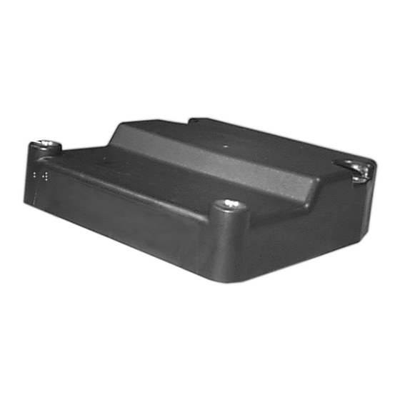
Bendix
EC-17
18 PIN
30 PIN
CONNECTOR
CONNECTOR
™
FIGURE 1 - EC-17
& EC-17N
DESCRIPTION
GENERAL
The EC-17
™
is an electronic antilock controller. It is the base
component in a family of full vehicle wheel control antilock
systems for buses, trucks and truck tractors. In addition to
the antilock function, the EC-17
assembled and programmed to provide an optional traction
control feature. Figure 1 shows the basic EC-17
controller configurations.
Designed to minimize the potential of brake lock up on all
wheels during aggressive braking, the EC-17
based antilock system provides the vehicle with a high
degree of stability and steerability during braking. In most
cases, vehicle stopping distance is also reduced. The
antilock portion of the EC-17
minimizes wheel skid during hard or aggressive braking. By
controlling wheel skid at all wheels on the vehicle, optimum
steering control and stopping distance is obtained.
Traction control, an optional feature in the full vehicle wheel
control antilock system, helps improve vehicle traction during
acceleration in adverse road conditions. Integrated with
antilock logic, traction control monitors wheel speed
AntiLock - Traction Controller
MOUNTING
HOLES
(4)
DIAGNOSTIC
DISPLAY
™
ANTILOCK TRACTION CONTROLLERS
™
controller can be
™
/EC-17N
™
controller
™
controller based system
information from the sensors during acceleration, as well as
braking. The system helps maintain vehicle stability on
hazardous road surfaces and improves driveability and safety.
™
The EC-17
controller contains a self configuring or learning
feature that allows it to be configured by the user when
installed on the vehicle. Because of this feature, all EC-17
controllers contain all the features and options available and
™
will activate the specific features required for the vehicle it is
installed on. The EC-17
vehicles with only antilock or vehicles using the traction
control feature. The procedure for activating the self
configuring feature is contained in the section entitled
"Configuring The EC-17
In order to provide full vehicle wheel control antilock, the
™
EC-17
controller is used in combination with the following
components:
- Four or six wheel speed sensors
- Four air pressure modulator valves
- One dash mounted antilock condition lamp
- One service brake relay valve
EC-17N
™
CONTROLLER
WITHOUT LED DIAGNOSTICS
EC-17
™
CONTROLLER
WITH LED DIAGNOSTICS
™
controller can be installed on
™
Controller".
™
1
Advertisement

Related Manuals for BENDIX EC-17 ANTILOCK TRACTION CONTROL


Summary of Contents for BENDIX EC-17 ANTILOCK TRACTION CONTROL
- Page 1 ® ® ™ Bendix EC-17 AntiLock - Traction Controller MOUNTING HOLES EC-17N ™ CONTROLLER WITHOUT LED DIAGNOSTICS 18 PIN 30 PIN CONNECTOR CONNECTOR DIAGNOSTIC DISPLAY EC-17 ™ CONTROLLER WITH LED DIAGNOSTICS ™ ™ FIGURE 1 - EC-17 & EC-17N ANTILOCK TRACTION CONTROLLERS...
- Page 2 ™ FIGURE 2 - EC-17 ANTILOCK TRACTION CONTROLLER SYSTEM SCHEMATIC...
- Page 3 When programmed to provide traction control in addition to function and replace the standard service relay on antilock antilock, the following components are added: equipped vehicles. In some instances the valves also provide specialized functions. When the EC-17 ™ controller is - One traction solenoid (incorporated into the relay valve) mounted on any of these valves, the result is a final assembly - One dash mounted traction condition lamp...
- Page 4 ™ FIGURE 5 - EC-17 ANTILOCK TRACTION CONTROLLER SYSTEM WIRING SCHEMATIC...
- Page 5 "report" its operating condition to an external computer using front, left front, right rear, left rear. It will execute this exhaust the Bendix diagnostic communications interface hardware sequence twice, for a total of eight exhausts. Both patented in response to certain commands it receives from software audible “Chuff”...
- Page 6 Solenoid valves contained in the modulator (hold ® ™ The Bendix EC-17 antilock system uses individual and exhaust) are energized and de-energized by the sensors, modulators and an electronic controller to control EC-17 ™...
- Page 7 ™ controller will instantly blink the traction dash lamp ® ™ ™ traction relay valve such as the Bendix ATR-1 or ATR-2 to advise the driver that a wheel spin is occurring. Additionally after mid-year 2000 the ECU requires J1922/ ™...
-
Page 8: Auto Calibration
AUTO CALIBRATION SYSTEM STILL OPERATING (YES/NO) For optional ATC performance the ECU utilizes a feature Failed ABS Front ABS Rear Traction Std. Device Left Right Left Right Braking referred to as auto calibration. Auto calibration allows the ECU to compensate for various tire sizes throughout the life RF Sensor YES YES of the vehicle. -
Page 9: Preventive Maintenance
If one or more of the LEDs DO NOT system pressure has been depleted. ILLUMINATE and the dash condition lamps indicate 8. Use only genuine Bendix ® replacement parts, the system is functioning properly, the non-illuminated components and kits. - Page 10 9. Components with stripped threads or damaged ™ INSTALLING THE EC-17 CONTROLLER parts should be replaced rather than repaired. Do not attempt repairs requiring machining or welding ™ EC-17 CONTROLLER MOUNTED ON unless specifically stated and approved by the ANTILOCK RELAY VALVE OR ANTILOCK vehicle and component manufacturer.
- Page 11 It can either be used as a “stand alone” diagnostic tool or with Bendix’s ACom For Windows software (part # 5004892). In order to use the DCI, the vehicle must be equipped with a J1587 diagnostic link connector as illustrated in Figure 9.
- Page 12 ™ /EC-17N ™ Red LED controller. Red LED Red LED For more information on the Bendix Diagnostic Red LED Communication Interface, see your local authorized Bendix Green LED parts outlet or call 1-800-AIR-BRAKE (1-800-247-2725). RESET + No LED OPTIONAL DIAGNOSTIC LEDS & RESET Note: The MID LED is used with some but not all vehicles.
- Page 13 sufficient to lift a three (3) ounce weight. Momentarily holding "RER" (Rear) LED a magnet against the RESET will cause ALL LEDs to light This Red LED illuminates in order to indicate the location of a during the time the magnet is against it. Holding a magnet component or its wiring.
- Page 14 connected. If mid axle speed sensors are not method the operator has to verify the system detected, the EC-17 ™ controller will default to a four operation. sensor configuration. (Two front and two rear) ™ 7. The EC-17 controller can be reprogrammed up to 10,000 times.
-
Page 15: Troubleshooting Tips
being configured with traction control (either torque TROUBLESHOOTING limiting, differential braking or both), the traction control IMPORTANT BEFORE TROUBLESHOOTING: condition dash lamp, will be illuminated as well as the appropriate LEDs on the EC-17 ™ controller diagnostic 1. Determine if the vehicle is equipped with traction control. display. -
Page 16: Quick Reference
DIAGNOSTIC DISPLAY QUICK REFERENCE This index is presented for the benefit of personnel experienced in troubleshooting Bendix full-vehicle wheel control antilock with traction control. It provides a quick reference to specific sections that provide testing procedures and values. NOTHING ON - GO... -
Page 17: Initial Start-Up Procedure
INITIAL START-UP PROCEDURE TURN IGNITION ON AND START HERE OBSERVE DASH ANTILOCK LAMP. ANTILOCK DASH LAMP DOES NOT BLINK, COMES ON AND DID ANTILOCK DASH LAMP BLINK? REMAINS ILLUMINATED IS ANTILOCK DASH LAMP GO TO SECTION II “INSPECTION STILL ILLUMINATED? FOR ILLUMINATED LEDS”... - Page 18 SECTION I - ANTILOCK DASH LAMP TESTING DISCONNECT 30 PIN CONNECTOR FROM START HERE EC-17 ™ CONTROLLER AND OBSERVE THE ANTILOCK DASH LAMP. REPLACE THE EC-17 ™ ANTILOCK DASH LAMP CONTROLLER ILLUMINATED? WITH IGNITION ON, MEASURE VOLTAGE BETWEEN PINS E3 & A1, A2, A3. VOLTAGE SHOULD BE SAME AS BATTERY VOLTAGE REPLACE RELAY &...
- Page 19 SECTION II - INSPECTION FOR ILLUMINATED LEDs INSPECT EC-17 ™ CONTROLLER FOR PRESENCE START HERE OF ILLUMINATED LEDS AND RECORD NO (OFF) CHECK CLOSELY AND NOTE IF GREEN, VLT LED IS ILLUMINATED ARE ANY RED LEDs ™ REPLACE THE EC-17 YES (ON) ILLUMINATED? CONTROLLER...
- Page 20 SECTION III - INSPECTION FOR ILLUMINATED LEDs INSPECT THE EC-17 ™ CONTROLLER START HERE FOR PRESENCE OF ILLUMINATED LEDS AND RECORD GO TO SECTION V ARE ANY RED “TESTING FOR POWER IS GREEN VOLT LED ILLUMINATED? LEDs ™ TO THE EC-17 ILLUMINATED? CONTROLLER”...
- Page 21 SECTION IV - INSPECTION FOR ILLUMINATED LEDs NOTE RED “ECU” LED IN START HERE ™ EC-17 CONTROLLER DIAGNOSTICS WINDOW. GO TO SECTION V “TESTING IS THIS LED ILLUMINATED? FOR POWER TO THE EC-17 ™ CONTROLLER” THERE SHOULD BE A MINIMUM OF THREE RED LEDs ILLUMINATED AND OF THE THREE THERE MUST BE A “RHT”...
- Page 22 SECTION V - TESTING FOR POWER TO THE EC-17 ™ CONTROLLER TURN IGNITION OFF, DISCONNECT 30 PIN START HERE CONNECTOR FROM EC-17 ™ CONTROLLER TURN IGNITION ON AND MEASURE VOLTAGE BETWEEN BATTERY PINS B1, K2, K3 AND GROUND PINS A1, A2, A3 ON WIRE HARNESS CONNECTOR ™...
- Page 23 ™ EC-17 CONTROLLER. 18 PIN CONNECTOR 30 PIN CONNECTOR PROBE CONNECTOR WITH VOLT/OHM METER AND NOTE THAT PROPER RESISTANCE VALUES ARE OBTAINED FOR MODULATOR BEING TESTED. RESISTANCE VALUES FOR BENDIX ® M-21 ™ M-22 ™ MODULATORS. F E D C B A...
- Page 24 CONNECTOR ON M-21 ™ OR M-22 ™ MODULATOR. GO TO MODULATOR, INSPECT WIRING CONNECTOR. DISCONNECT CONNECTOR AND TEST RESISTANCE BETWEEN PINS ON MODULATOR. RESISTANCE VALUES FOR BENDIX ® M-21 ™ AND M-22 ™ START HERE FROM MODULATORS. SECTION VI A HOLD TO COMMON: READ 3.5 TO 5 OHMS...
- Page 25 ™ SENSOR SHOULD BE ABOVE 0.250 VOLTS AC AT 0.5 RPS. IF VOLTAGE IS BELOW THE MINIMUM CHECK ITEMS BELOW A. CHECK "GAP" BETWEEN SPEED SENSOR AND EXCITER OR TONE RING. (GAP FOR BENDIX ® WS-20 ™ SENSOR, SPEED SENDER IS BETWEEN 0 - .015 INCHES) IF SENSOR GAP MUST BE ADJUSTED, CHECK FOR LOOSE OR WORN WHEEL BEARINGS BEFORE RE- GAPPING SENSOR.
- Page 26 ™ IGNITION OFF. REMOVE CONNECTOR FROM EC-17 CONTROLLER. MEASURE RESISTANCE BETWEEN THE 30 PIN CONNECTOR APPROPRIATE SPEED SIGNAL (+) AND SIGNAL RETURN (-). RESISTANCE FOR BENDIX ® SENSORS IS BETWEEN 1500- 2500 OHMS. REFER TO VEHICLE MANUAL FOR THE ™...
- Page 27 SECTION VIII - TESTING FOR FALSE INDICATION CAUSED BY DASH LIGHT RELAY WITH IGNITION ON, HOLD MAGNET START HERE ON EC-17 ™ CONTROLLER RESET AND NOTE ALL LEDs ARE ILLUMINATED. E3 TO DASH LAMP RELAY REPLACE THE EC-17 ™ ARE ALL LEDs ILLUMINATED? CONTROLLER ™...
- Page 28 APPROPRIATE SPEED SENSOR “PIN PAIR” WHILE SPINNING WHEEL BY HAND (REFER TO FIGURE 5 FOR THE SPEED SENSOR PIN PAIR LOCATION IN THE 18 OR 30 PIN CONNECTOR). VOLTAGE OUTPUT FOR BENDIX WS-20™ SENSOR ™ EC-17 CONTROLLER SHOULD BE ABOVE 0.8 VOLTS AC AT 1 RPS.
- Page 29 SECTION X - TESTING TRACTION CONTROL DASH LAMP REPLACE TRACTION DASH LAMP WITH IS THIS THE SECOND TIME TO START HERE KNOWN GOOD UNIT. REPEAT "INITIAL THIS POINT? START-UP PROCEDURE" WITH IGNITION OFF, REMOVE 30 PIN CONNECTOR FROM EC-17 ™ CONTROLLER.
- Page 30 SECTION XI - TESTING TRACTION CONTROL MODULATOR WITH IGNITION ON, INSPECT EC-17 ™ START HERE CONTROLLER FOR ILLUMINATED LEDs IS "TRC" ONLY ON? GO TO SECTION XII "TESTING ENGINE ARE "TRC" AND "MOD" These LEDs CONTROL MODULE WIRE HARNESS" LEDs ON? Illuminated? TURN IGNITION OFF AND REMOVE 18 PIN CONNECTOR FROM EC-17™...
- Page 31 SECTION XII - TESTING ENGINE CONTROL MODULE WIRE HARNESS PASS MAGNET OVER EC-17 ™ START HERE TRC ONLY RED LED ON? CONTROLLER RESET & REPEAT "INITIAL START-UP PROCEDURE" TURN IGNITION OFF. DISCONNECT 30 PIN ™ CONNECTOR FROM EC-17 CONTROLLER & 2 or 3 PIN CONNECTOR AT ENGINE ELECTRONIC CONTROL MODULE.
- Page 32 BW1910 © 2004 Bendix Commercial Vehicle Systems LLC All rights reserved. 5/2004 Printed in U.S.A.
Need help?
Do you have a question about the EC-17 ANTILOCK TRACTION CONTROL and is the answer not in the manual?
Questions and answers