Table of Contents
Advertisement
®
Bendix
EC-60
®
™
See SD-13-4863 for Standard and Premium Controllers
See SD-13-21021 for the Bendix
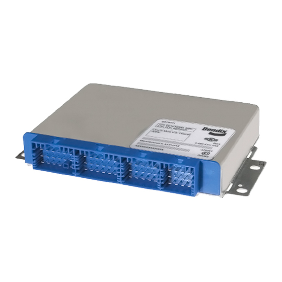
All Four Connectors Are Used.
(If only two or three connectors are in
use - see SD-13-4863)
FIGURE 1 - EC-60
ADvAnCED COnTROLLER
™
INTRODUCTION
The Bendix
EC-60
advanced controller is a member
®
™
of a family of electronic Antilock Braking System
(ABS) devices designed to help improve the braking
characteristics of air braked vehicles - including heavy- and
medium-duty buses, trucks, and tractors. ABS controllers
are also known as Electronic Control Units (ECUs).
Bendix
ABS uses wheel speed sensors, ABS pressure
®
modulator valves, and an ECU to control either four or six
wheels of a vehicle. The Bendix EC-60 controller monitors
individual wheel turning motion during braking and adjusts
or modulates the brake pressure at the wheel end. When
excessive wheel slip, or wheel lock-up is detected, the
Bendix EC-60 controller will activate the pressure modulator
valves to automatically reduce the brake pressure at one
or more of the wheel ends. By these actions, the ABS
system helps to maintain the vehicle's lateral stability and
steerability during heavy brake applications and during
braking on slippery surfaces.
In addition to the ABS function, advanced models of the
EC-60
controller provide ABS-based stability features
™
referred to as ESP
Electronic Stability Program. The
®
Bendix ESP system is an ABS-based stability system that
enhances vehicle stability by both reducing engine throttle
and by applying vehicle braking based on actual vehicle
dynamics. Accordingly, the ESP system is available only on
specific approved vehicle platforms after vehicle application
and development efforts and validation testing. Only
certain limited variations of an approved vehicle platform
are permitted without further validation of the ESP system
application.
ESP stability system consists of Yaw Control (YC) and Roll
Stability Program (RSP) features.
ESP
is a registered trademark of DaimlerChrysler and is used by BCVS under license from DaimlerChrysler.
®
ABS / ATC / ESP Controllers (Advanced)
eTrac
Automated Air Suspension Transfer System
®
™
The driver is always responsible for the control
and safe operation of the vehicle at all times . The
Bendix
ESP
stability system does not replace the
®
®
need for a skilled, alert professional driver, reacting
appropriately and in a timely manner, and using safe
driving practices .
TABLE OF CONTENTS
General System Information
Introduction . . . . . . . . . . . . . . . . . . . . . . . 1
Components . . . . . . . . . . . . . . . . . . . . . 3-4
Hardware Configurations . . . . . . . . . . . . . . . 4
Bendix EC-60 Controller Inputs & Outputs . . . . . 5-7
Indicator Lamps And Power-Up Sequence . . . . . 8-9
Abs Operation . . . . . . . . . . . . . . . . . . . . . 9
Atc Operation . . . . . . . . . . . . . . . . . . 11-12
Advanced ABS With Stability . . . . . . . . . . 12-13
The Esp Stability System . . . . . . . . . . . . 13-14
Dynamometer Test Mode . . . . . . . . . . . . . . 14
System Reconfiguration . . . . . . . . . . . . . . . 16
Troubleshooting . . . . . . . . . . . . . . . . . 17-48
Sensor Calibration . . . . . . . . . . . . . . . . 17-19
Blink Codes And Diagnostic Trouble Codes . . 21-23
Wiring Schematic . . . . . . . . . . . . . . . . . . 48
Glossary . . . . . . . . . . . . . . . . . . . . . . . . 49
J1587 Sid And Fmi Codes . . . . . . . . . . . . 51-55
Uds Codes . . . . . . . . . . . . . . . . . . . . 56-60
Additional features include Automatic Traction Control
(ATC). Bendix ATC can improve vehicle traction during
acceleration, and lateral stability while accelerating through
curves. ATC utilizes Engine Torque Limiting (ETL)
where the ECU communicates with the engine's controller
and/or Differential Braking (DB) where individual wheel
brake applications are used to improve vehicle traction.
Advanced Bendix Ec-60 Controllers have a drag torque
control feature which reduces driven-axle wheel slip (due
to driveline inertia) by communicating with the engine's
controller and increasing the engine torque.
For vehicles with the Hill Start Feature optional feature,
this system interfaces between the transmission and
braking system to help the driver prevent the vehicle from
rolling downhill when moving up a steep incline from a
stationary position.
PAGE
1
Advertisement
Table of Contents
Troubleshooting

Related Manuals for BENDIX EC-60 ABS


Summary of Contents for BENDIX EC-60 ABS
- Page 1 Hardware Configurations . . . . . . . . . . . . . . . 4 The Bendix EC-60 advanced controller is a member Bendix EC-60 Controller Inputs & Outputs . . . . . 5-7 ® ™ of a family of electronic Antilock Braking System Indicator Lamps and Power-Up Sequence .
- Page 2 Control" on page 12 for further details. Other factors such as driving too fast for road, traffic or Accordingly, the Bendix EC-60 controller is provided with weather conditions, oversteering, an excessively high a corresponding parameter data set that is validated for vehicle Center of Gravity (CG), or poor road conditions can a specific vehicle platform.
- Page 3 See "Yaw Stability" on page 9 for further details. ROLL STABILITY PROGRAM (RSP) Electrical M-32 ™ The Bendix Roll Stability Program (RSP), is an all-axle Connector M-32QR ™ Modulator Modulator ABS solution that helps reduce vehicle speed by reducing...
- Page 4 ™ • Bendix AT-3 Traction control valve ® ™ system is used on 6 x 2 semi-tractors that feature Bendix ® • Dash-mounted HSA Status/indicator lamp premium and advanced Antilock Brake Systems (ABS). This system complements the Bendix Smart Automatic •...
- Page 5 Vp-p. Suggested oscilloscope settings are AC coupling, 1 volt/div, 100 µsec/div. The signal should be measured at the ignition power input of the Bendix EC-60 controller. Note: An ABS trailer equipped with PLC, or a PLC diagnostic tool, must be connected to the vehicle in order...
- Page 6 J1939 message to the of the vehicle load. It is typically installed in one of the Bendix EC-60 controller. suspension air bags. (If you need to know if this Bendix EC-60 controller uses Bendix SAS-60 Steering Angle Sensor ®...
- Page 7 ® ™ (If you need to know if this Bendix EC-60 controller uses a operate the lamp, e-mail ABS@bendix.com, specifying the serial communications message to operate the lamp, e-mail ECU part number, or call 1-800-AIR-BRAKE and speak to ABS@bendix.com, specifying the ECU part number, or call...
- Page 8 *Some vehicle manufacturers may illuminate the trailer ABS indicator lamp at power-up regardless of whether a PLC signal is detected from the trailer or not. Consult the vehicle manufacturer’s documentation for more details. CHART 2 - BEnDix EC-60 inDiCATOR LAMP BEHAviOR ®...
- Page 9 (if the vehicle moves the chuff test will not be performed). The ECU will illuminate the ATC/ESP lamp for approximately The Bendix EC-60 controller will perform a PMV chuff test 2.5 seconds when ignition power is applied, after which the...
- Page 10 EC-60 controller blends the applied braking force between ABS may be longer than without ABS. This can occur the two steering axle brakes. This Bendix patented brake when a locked wheel on soft ground or loose gravel plows application control, called Modified Individual Regulation...
- Page 11 5. If ATC Differential Braking function is activated for a long control as the ABS function. The Bendix EC-60 controller time period to avoid overheating of the brakes. It would detects excessive drive wheel speed, compares the speed...
- Page 12 If the vehicle shows a tendency to leave include Roll Stability Program (RSP) and Yaw Control. During operation, the ECU of the Bendix Advanced ABS an appropriate travel path, or if critical threshold values are system constantly compares performance models to the approached, the system will intervene to assist the driver.
- Page 13 Always operate the vehicle safely, drive defensively, anticipate obstacles and pay attention to road, weather Bendix RSP, an element of the overall ESP system, and traffic conditions. ABS, ATC and ESP stability addresses rollover conditions. In the case of a potential systems are no substitute for prudent, careful driving.
- Page 14 (e .g . visor labels, etc .) used and release the blink code switch three times, or use a to show that Bendix ESP was installed and make any hand-held or PC-based diagnostic tool. necessary notations in the vehicle manual(s), so that drivers do not misunderstand which ABS options are installed on the vehicle .
- Page 15 ABS, ATC, and ESP functions may be fully or partially disabled. Even with the ABS indicator lamp ESP is disabled. ABS and ATC remain active. illuminated, the Bendix EC-60 controller may still provide ABS function on wheels that are not affected. The ABS Yaw Rate/Lateral Acceleration Sensor system controller should be serviced as soon as possible.
- Page 16 SYSTEM RECONFIGURATION Reconfiguration Using the Blink Code Switch With ignition power removed from the Bendix EC-60 The Bendix EC-60 controller is designed to allow the ® ™ controller, depress the blink code switch. After the ignition technician to change the default system settings (chosen power is activated, depress and release the switch seven by the vehicle OEM) to provide additional or customized times to initiate a reconfiguration event.
- Page 17 If the VIN stored in the ECU does not match the VIN obtained from the other vehicle controller, the ECU will 3. Note the Bendix EC-60 controller assembly mounting generate an ECU Internal VIN Mismatch DTC . position on the vehicle.
- Page 18 Make sure all connections are free from visible damage. 2. Record the part number of the Bendix EC-60 Advanced Controller. 2. Examine the sensor. Make sure the sensor, its mounting screws, and the interface between the hub 3.
- Page 19 46Nm (±9 properly recalibrated as needed, the yaw control Nm). Note that the Bendix YAS-70X sensor has two system may not function properly, which can result alternate designs, one with an aligning post — see the in a loss of vehicle control .
- Page 20 1. Check all wiring and connectors. Make sure all a component approved for use with the Bendix Advanced connections are free from visible damage. ABS system. However, replacement of brake demand 2.
- Page 21 Troubleshooting: Blink Codes and Diagnostic Modes ECU DIAGNOSTICS In addition, by operating the blink code switch as described below, one of several diagnostic modes can be entered. The Bendix EC-60 controller contains self-testing ® ™ See Diagnostic Modes below. diagnostic circuitry that continuously checks for the normal...
- Page 22 Inactive trouble codes, and event history, may be retrieved Press the System Mode Entered and cleared by using a hand-held or PC-based diagnostic Blink Code Switch tool, such as the Bendix ACom Diagnostics software. ® ® Active diagnostic trouble code retrieval...
- Page 23 Troubleshooting and diagnostic trouble code clearing (as 4 Modulators well as reconfiguration) may also be carried out using 5 Modulators hand-held or PC-based diagnostic tools such as the Bendix Remote Diagnostic Unit (RDU ), Bendix ACom 6 Modulators ® ™ ® ®...
- Page 24 9 pin diagnostic connector ™ RDU is not capable of diagnosing ESP-specific diagnostic in the cab of the vehicle. An adapter cable (Bendix part trouble codes including additional sensors: steering angle number 801872) is available to connect the RDU to vehicles sensors, yaw sensors, pressure sensors, or modulator with a 6-pin diagnostic connector.
- Page 25 When using ACom Diagnostics V4.0 (or higher) software ® to diagnose the Bendix EC-60 ABS ECU, the computer’s Nexiq Bendix Application Card serial or parallel port needs to be connected to the vehicle’s Nexiq provides a Bendix application card for use with the diagnostic connector.
- Page 26 For the first sequence go to page 27 and for the second sequence go to page 34. See Page 51 for APPENDIx B: J1587 SID and FMI Codes and their Bendix Blink Code Equivalents See Page 56 for APPENDIx C: UDS Codes and their Bendix Blink Code Equivalents...
- Page 27 Troubleshooting Diagnostic Trouble Codes: Wheel Speed Sensors 1st . Blink Location Code Left Steer Axle Sensor Right Steer Axle Sensor Left Drive Axle Sensor Right Drive Axle Sensor Left Additional Axle Sensor Right Additional Axle Sensor 2nd . Diagnostic Trouble Repair Information Blink Code Description...
- Page 28 Speed Sensor Repair Tests: 1. Take all measurements at ECU harness connector pins in order to check wire harness and sensor. Probe the connector carefully so that the terminals are not damaged. 2. Wheel speed sensor measurements should read: Location Measurement Sensor 1500 - 2500 Ohms...
- Page 29 Troubleshooting Diagnostic Trouble Codes: Power Supply 1st . Blink Location Code Power Supply 2nd . Diagnostic Trouble Repair Information Blink Code Description Code Battery Voltage Too Low Measure battery voltage under load. Check vehicle battery and associated components. Check for damaged wiring. Check for damaged or corroded connectors and connections.
- Page 30 Troubleshooting Diagnostic Trouble Codes: Pressure Modulator Valves 1st . Blink Location Code Left Steer Axle Right Steer Axle Left Drive Axle Right Drive Axle Left Additional Axle Right Additional Axle Trailer PMV 2nd . Diagnostic Repair Information Blink Trouble Code Code Description Release Solenoid...
- Page 31 Pressure Modulator Valve Repair Tests: 1. Take all measurements at ECU harness connector pins in order to check wire harness and PMV. Probe the connector carefully so that the terminals are not damaged. 2. Pressure modulator resistance should read: Location Measurement Release to Common 4.9 to 5.5 Ohms...
- Page 32 Verify presence of retarder on the J1939 link. Verify ECU Configuration. Check for other devices inhibiting J1939 communications. Loss of communications between the Bendix EC-60 controller and the engine ECU J1939 Engine over the J1939 link. Check for damaged or reversed J1939 wiring. Check for corroded Communications or damaged connectors.
- Page 33 Cab-mount ECU: J1939 Troubleshooting Tests: 1. Take all measurements at ECU harness Looking into wire harness connector connector 2. Check for damaged or reversed J1939 wiring 3. Check for corroded or damaged wiring connector problems such as (opens or shorts to voltage or ground) Connector J1939 4.
- Page 34 Check wiring between ECU and retarder relay or HSA lamp. Verify no continuity between Lamp Circuit Shorted to retarder disable output or HSA lamp output of Bendix EC-60 controller and voltage. Verify Voltage condition and wiring of the retarder relay or HSA lamp.
- Page 35 Troubleshooting Diagnostic Trouble Codes: Miscellaneous Continued 1st . Blink Location: Code Miscellaneous 2nd . Diagnostic Trouble Blink Repair Information Code Description Code Diff. Lock Solenoid Verify no continuity between the Diff Lock Solenoid and ground. Check for corroded/ Shorted to Ground or damaged wiring or connectors between the ECU and Diff Lock Solenoid.
- Page 36 ECU DTC '11' wiring including power and ground wiring. Clear the trouble codes. If Diagnostic Trouble ECU DTC '12' Codes (DTCs) return, contact the Bendix Tech Team at 1-800-AIR-BRAKE (1-800-247- ECU DTC '13' 2725) for further troubleshooting assistance. ECU DTC '14'...
- Page 37 Troubleshooting Diagnostic Trouble Codes: Traction Control Valves 1st . Blink Location Code Drive Axle Traction Control Valve Steer Axle Traction Control Valve nOTE: Also see ECU 13-8 and 13-18 DTC repair information on page 36, for a potential connection between these TCv DTCs and ECU DTCs.
- Page 38 Troubleshooting Diagnostic Trouble Codes: Steering Angle Sensor (SAS-60 sensor) ™ 1st . Blink Location: Code Steering Angle Sensor 2nd . Diagnostic Trouble Blink Repair Information Code Description Code SAS Not Calibrated SAS has not been calibrated. Perform SAS calibration procedure. SAS Calibration in SAS calibration procedure is underway.
- Page 39 6 . To test the Steering Angle Sensor, ACom V4.0, or Verify continuity between ECU and SAS-60 and higher, is required. Using Bendix ACom V4.0 or higher, YAS-60. select the “Component Test” option, followed by the...
- Page 40 DTC does not clear even after the S-shaped driving maneuver, check and correct the orientation of the YRS and repeat maneuver. YRS - Vibration Inspect YRS mounting and verify it is securely mounted. Note that YRS may not be Detected relocated from OEM-installed position on vehicle without written Bendix Engineering approval.
- Page 41 1 . Verify continuity between ECU and YAS-60. 6 . To test the Yaw Rate Sensor, ACom V4.0, or higher, is Connector Function required. Using Bendix ACom V4.0 or higher, select the Power “Component Test” option, followed by the “ESP Test” Ground option.
- Page 42 Troubleshooting Diagnostic Trouble Codes: Lateral Acceleration Sensor (LAS) 1st . Blink Location: Code Lateral Acceleration Sensor 2nd . Diagnostic Trouble Blink Repair Information Code Description Code LAS signal incorrect. Verify proper installation of the YRS/LAS. Verify proper LAS Signal Out of Range wiring between the ECU and the YRS/LAS.
- Page 43 Troubleshooting Diagnostic Trouble Codes Brake Demand/Load Sensors 1st . Blink Location: Code Brake Demand/ Load Sensor 2nd . Diagnostic Trouble Blink Repair Information Code Description Code PS1 Open or Shorted Check wiring between Brake Demand Sensor (primary brake circuit) and ECU. Verify operation of pressure sensor.
- Page 44 Connector Part Numbers and Pin Assignments: ADVANCED CAB CONNECTOR CONNECTOR CONNECTOR CONNECTOR Advanced Cab Bendix EC-60 Controller Advanced cab models utilize four AMP connectors for wire harness connections. x1 Connector Pin x2 Connector Pin x3 Connector Pin x4 Connector Pin...
- Page 45 : All wires must be carefully routed to avoid ECU Wiring Harness Connectors contact with rotating elements. Wiring must be properly secured approximately every 6 to 12 inches using UV The Advanced Bendix EC-60 controller is designed to ® ™...
- Page 46 Robert Bosch 1 928 404 025, Wire Harness Connectors: Robert Bosch 1 928 498 001 Metri-Pack (Packard) 1206 5287 One Meter Adapter to Connector: Contact Pins: Bendix 5015242 (shown) Packard 1210 3881 Packard 12092162, pins 12064971 CHART 4 - EC-60 COnTROLLER COMPOnEnT COnnECTORS ™...
- Page 47 ™ Wheel Speed Sensor Wiring Route sensor wiring coming out of the wheel ends away Bendix does not recommend using standard tie-wraps to from moving brake components. Sensor wiring needs to secure wiring harnesses directly to rubber air lines. This...
- Page 48 Troubleshooting: Wiring Schematic FIGURE 20 - STAnDARD CAB WiRing SCHEMATiC...
- Page 49 Glossary ABS — Antilock Brake System. IR — Independent Regulation. A control method in which a wheel is controlled at optimum slip, a point where retardation and stability ABS Event — Impending wheel lock situation that causes the are maximized. The brake pressure that is best for the wheel in ABS controller to activate the modulator valve(s).
- Page 50 (top-left side) and remove Pins 1, 2, 11 &12. Reconnect X2-18 the connector and apply IGN power to the ECU. Using Bendix ACom Diagnostics, clear all DTCs. If the 12-7 DTC returns, the problem is either the wiring harness inside the cab or the ECU.
- Page 51 APPENDIx B: J1587 SID and FMI Codes and their Bendix Blink Code Equivalents Bendix Blink Code Equivalent(s) (J1587/ Diagnostic Trouble Code Description (J1587) (J1939) J1939) (1st Digit) (2nd Digit) No DTCs Wheel Speed Sensor DTCs SA Left WSS Excessive Air Gap...
- Page 52 APPENDIx B: J1587 SID and FMI Codes and their Bendix Blink Code Equivalents Bendix Blink Code Equivalent(s) (J1587/ Diagnostic Trouble Code Description (J1587) (J1939) J1939) (1st Digit) (2nd Digit) Miscellaneous DTCs Retarder Relay or HSA Lamp Open Circuit or Shorted to Ground...
- Page 53 APPENDIx B: J1587 SID and FMI Codes and their Bendix Blink Code Equivalents Bendix Blink Code Equivalent(s) (J1587/ Diagnostic Trouble Code Description (J1587) (J1939) J1939) (1st Digit) (2nd Digit) Miscellaneous DTCs 1045 Stop Lamp Switch Defective 1045 Brake Lamp Input Mismatch with Brake Lamp Output...
- Page 54 APPENDIx B: J1587 SID and FMI Codes and their Bendix Blink Code Equivalents Bendix Blink Code Equivalent(s) (J1587/ Diagnostic Trouble Code Description (J1587) (J1939) J1939) (1st Digit) (2nd Digit) Miscellaneous DTCs HSA Solenoid Shorted to Voltage (high) HSA Solenoid Shorted to Ground (Low) or Open circuit...
- Page 55 APPENDIx B: J1587 SID and FMI Codes and their Bendix Blink Code Equivalents Bendix Blink Code Equivalent(s) (J1587/ Diagnostic Trouble Code Description (J1587) (J1939) J1939) (1st Digit) (2nd Digit) ECU DTCs ECU (1C) ECU (27) ECU (1D) ECU (1E) ECU (28)
- Page 56 APPENDIx C: UDS Codes and their Bendix Blink Code Equivalents Lamp J1587 J1939/73 Status Spec . PID194 DM1/2 DTC Description Code Blink (SID/ ATC/ SPN/FMI Code FMI) 01-01 000-00 no DTC 14-03 005-02 0793-02 AA Left WSS Open or Shorted...
- Page 57 APPENDIx C: UDS Codes and their Bendix Blink Code Equivalents Lamp J1587 J1939/73 Status Spec . PID194 DM1/2 DTC Description Code Blink (SID/ ATC/ SPN/FMI Code FMI) 12-05 013-03 0801-03 Retarder Relay Circuit Shorted to Voltage 12-05 094-03 2622-03 Retarder Relay Circuit or Hill Start Assist Lamp Shorted to...
- Page 58 APPENDIx C: UDS Codes and their Bendix Blink Code Equivalents Lamp J1587 J1939/73 Status Spec . PID194 DM1/2 DTC Description Code Blink (SID/ ATC/ SPN/FMI Code FMI) 21-07 089-02 1807-02 SAS Gradient Error 21-09 089-02 1807-02 SAS Long Term Calibration Error...
- Page 59 APPENDIx C: UDS Codes and their Bendix Blink Code Equivalents Lamp J1587 J1939/73 Status Spec . PID194 DM1/2 DTC Description Code Blink (SID/ ATC/ SPN/FMI Code FMI) 03-02 002-14 0790-14 SA Right WSS Output Low @ Drive-Off 03-06 002-08 0790-08...
- Page 60 LAS Plausibility Error (Outside Model Based Limits) 17-08 012-13 0800-13 AA Right PMV Configuration Error Log-on and Learn from the Best On-line training that's available when you are 24/7/365. Visit www.brake-school.com. SD-13-4869_US_003 © 2013 Bendix Commercial Vehicle Systems LLC • All Rights Reserved • 6/13...
Need help?
Do you have a question about the EC-60 ABS and is the answer not in the manual?
Questions and answers