Table of Contents
Advertisement
Quick Links
Bendix Brake Chambers
DESCRIPTION
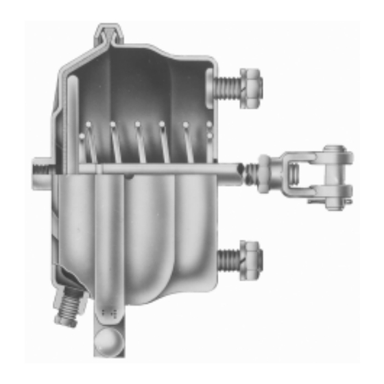
The brake chamber is a diaphragm type actuator which
converts the energy of air pressure into mechanical force.
The diaphragm is held between the pressure plate and non-
pressure plate by either a one piece clamp ring or a two
piece clamp ring (Figs. 1 and 2).
INLET PORT
DIAPHRAGM
PRESSURE PLATE
INLET PORT
CLAMP RING
NUTS & BOLTS
CLAMP RING
Different size brake chambers are identified by numbers
which specify the effective area of the diaphragm. A type
30 brake chamber has 30 square inches effective area.
Since one side of a brake chamber diaphragm is exposed
to the applying air pressure and the other side to atmospheric
pressure, the chamber has a pressure and a non-pressure
side. The non-pressure plate is usually vented to atmosphere
with four holes, however, on those installations where the
chamber must be weather-proof, venting is accomplished
through a drilled passage in the mounting bolts and the rod
opening in the non-pressure plate is sealed by either a
boot or an o-ring seal.
The standard diaphragm material is a compound of natural
rubber with a fabric interior of nylon. Neoprene-nylon
diaphragms are optionally available.
Smaller chambers such as type 3 and type 6 have one 1/4
in. NPT inlet port in the center of the pressure plate. Larger
size chambers may have a center port and a side located
port or either one. Current production Type 20 chambers
and larger, generally have 3/8 in. NPT ports to facilitate
compliance with FMVSS 121.
NON
PRESSURE
SPRING
PLATE
PUSH ROD
ASSY.
LOCK NUT
MOUNTING
BOLTS
YOKE
1
Advertisement
Table of Contents

Related Manuals for BENDIX BRAKE CHAMBERS


Summary of Contents for BENDIX BRAKE CHAMBERS
- Page 1 Bendix Brake Chambers Different size brake chambers are identified by numbers which specify the effective area of the diaphragm. A type 30 brake chamber has 30 square inches effective area. Since one side of a brake chamber diaphragm is exposed...
- Page 2 For example, if 60 psi is admitted to a type projections for rotochambers and bolt projections for 30 brake chamber, the lineal force on the end of the push clamp type brake chambers. rod is approximately 1800 lbs. FIGURE 3 When air pressure is released from the brake chamber, the 2.
- Page 3 3. Replace all rubber parts and all other parts not contact with moving, rotating, leaking, heated or considered serviceable with genuine Bendix replacement electrically charged components. parts. 3. Do not attempt to install, remove, disassemble or...
- Page 4 ON) prior to performing any vehicle maintenance where one or more wheels on a drive axle are lifted off the ground and moving. BW1426 © 2007 Bendix Commercial Vehicle Systems LLC. All rights reserved. 3/2007 Printed in U.S.A.
Need help?
Do you have a question about the BRAKE CHAMBERS and is the answer not in the manual?
Questions and answers