Advertisement
Quick Links
®
®
™
Bendix
EC-15
™
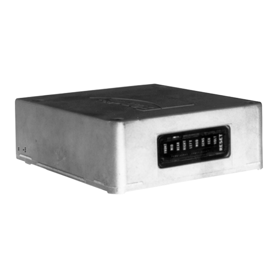
FIGURE 1 - EC-15
ELECTRONIC CONTROLLER
DESCRIPTION
GENERAL
Bendix antilock systems utilizing the EC-15
controller assembly provide full vehicle, wheel control braking
for buses, trucks, and truck tractors. By minimizing the
potential of "brake lock-up" on all wheels during aggressive
braking the vehicle retains a high degree of stability and
steerability, and in most cases vehicle stopping distance is
reduced.
In order to provide full vehicle, wheel control braking, the
™
EC-15
controller assembly is used in combination with the
following components:
- Four, individual wheel speed sensors
- Four, air pressure modulator valves
- Antilock condition lamp (dash mounted)
AntiLock Controller Assembly
™
electronic
MOUNTING
HOLES (4)
DIAGNOSTICS
WINDOW DISPLAY
PHYSICAL
The EC-15
™
controller electronics, that regulate the function
of the antilock system, are contained in a die cast aluminum
housing and are environmentally protected. The metal
housing, coupled with the design of the digital electronics,
is intended to provide a high degree of protection from radio
and electromagnetic interference.
A diagnostics display window with 9 light emitting diodes
(LEDs) and a magnetically actuated reset switch is
incorporated in the housing for troubleshooting and
diagnostic purposes.
Two types of electrical connectors are currently used to
connect the EC-15
™
controller assembly to the antilock
system components; a single, 30 pin, Packard Electric,
150 series "Metri-pack" or a pair of 14 pin, Deutsch, HID 30
series connectors.
1
Advertisement

Related Manuals for BENDIX EC-15 ANTILOCK CONTROLLER ASSY


Summary of Contents for BENDIX EC-15 ANTILOCK CONTROLLER ASSY
- Page 1 GENERAL PHYSICAL The EC-15 ™ controller electronics, that regulate the function Bendix antilock systems utilizing the EC-15 ™ electronic of the antilock system, are contained in a die cast aluminum controller assembly provide full vehicle, wheel control braking housing and are environmentally protected. The metal for buses, trucks, and truck tractors.
- Page 2 ™ ™ FIGURE 2 - EC-15 /CR-15 ANTILOCK SYSTEM...
-
Page 3: Controller Inputs/Outputs
Some ™ portions of the EC-15 controller both receive and deliver ® ™ Modulators, like the Bendix M-21 , are the means by which commands and information. ™ the EC-15 antilock controller is able to modify driver applied air pressure to the service brakes. -
Page 4: Operation
OPERATION air passes on its way to the brake actuator. A wiring harness GENERAL ™ connects the modulator to the EC-15 antilock controller. The Bendix ® EC-15 ™ antilock controller system provides Solenoid valves contained in the modulator provide the individual wheel control by using a wheel speed sensor and ™... - Page 5 EXCITER RING (100) TOOTH WS-20 ™ ANGLED SENSOR HUB ASSEMBLY WS-20 ™ STRAIGHT WS-20 ™ SPEED SENSOR SENSOR PACKARD DEUTSCH CONNECTOR CONNECTOR ™ FIGURE 5 - WS-20 WHEEL SPEED SENSORS ANTILOCK CONTROLLED BRAKE In the case of vehicles equipped with tandem rear axles (6x2, 6x4), the wheel speed sensors are installed at the APPLICATION SYSTEM FULLY OPERATIONAL wheels on the axle that is most likely to lose traction first.
- Page 6 It should be remembered that the driver will be COMPONENT FAILURE advised of the degraded antilock operation via the dash ® ™ The Bendix EC-15 controller handles equipment failure lamp and that standard air braking will still be available on using a conservative fail-safe philosophy. Any single electrical...
-
Page 7: Preventative Maintenance
1. Check all wiring and connectors to ensure they are system pressure has been depleted. secure and free from visible damage. ® 8. Use only genuine Bendix replacement parts, ™ 2. Although the EC-15 controller incorporates a self check components and kits. - Page 8 ™ FIGURE 7 - WIRING SCHEMATIC FOR EC-15 CONTROLLER WITH DEUTSCH CONNECTORS...
- Page 9 FIGURE 9 - WIRING SCHEMATIC FOR EC-15 ™ CONTROLLER WITH PACKARD CONNECTOR...
- Page 10 ™ BRACKET MOUNTED EC-15 CONTROLLER DIAGNOSING AND LOCATING A SYSTEM ™ 1. Disconnect the electrical connector(s) from the EC-15 PROBLEM controller. GENERAL 2. Note and mark the mounting position of the EC-15 ™ The EC-15 ™ controller contains self test and diagnostic controller on the vehicle.
- Page 11 “LEFT” LED LED o FRONT Red LED LED o MID Red LED (SEE NOTE BELOW) This Red LED illuminates and latches ON in order to indicate LED o REAR Red LED LED o RIGHT Red LED the location of a problem component or its wiring. It will light LED o LEFT Red LED in conjunction with either the FRONT or REAR LED and the...
-
Page 12: Troubleshooting Tips
TROUBLESHOOTING GENERAL ™ While the EC-15 controller diagnostic display locates a specific problem area, it is still necessary to confirm whether the problem resides in the component itself or the wiring. Basically the troubleshooting procedure that follows is devoted to narrowing the problem to either the wiring or a specific antilock component. - Page 13 TROUBLESHOOTING INITIAL START-UP PROCEDURE TURN VEHICLE IGNITION ON. START HERE OBSERVE DASH ANTILOCK CONDITION LAMP. GO TO SECTION I IS DASH LAMP ILLUMINATED? “DASH LAMP TESTING” GO TO SECTION II DASH LAMP DOES NOT BLINK, IT COMES “INSPECTION FOR ON AND REMAINS ON. ILLUMINATED LED(S)”...
- Page 14 TROUBLESHOOTING SECTION I - DASH LAMP TESTING DISCONNECT WIRE HARNESS CONNECTOR FROM EC-15 ™ CONTROLLER (FRONT START HERE CONNECTOR ONLY IN FIGURE 7) AND OBSERVE THE DASH LAMP. ™ REPLACE THE EC-15 DASH LAMP ILLUMINATED? CONTROLLER WITH IGNITION ON, MEASURE VOLTAGE BETWEEN LAMP RELAY AND GROUND.
- Page 15 TROUBLESHOOTING SECTION II - INSPECTION FOR ILLUMINATED LEDS ™ INSPECT EC-15 CONTROLLER FOR PRESENCE OF START HERE ILLUMINATED LEDS AND RECORD. CHECK CLOSELY NO (OFF) AND NOTE IF GREEN LED IS ILLUMINATED ARE ANY RED REPLACE YES (ON) LED’S THE EC-15 ™...
- Page 16 TROUBLESHOOTING SECTION III - INSPECTION FOR ILLUMINATED LED’S INSPECT THE EC-15 ™ CONTROLLER FOR PRESENCE OF ILLUMINATED LEDS START HERE AND RECORD. GO TO SECTION ARE ANY RED IS GREEN, VOLT, LED V “TESTING FOR LED’S ILLUMINATED? POWER TO THE ILLUMINATED? EC-15 ™...
- Page 17 TROUBLESHOOTING SECTION IV - INSPECTION FOR ILLUMINATED LEDS. NOTE RED “ECU” LED IN START HERE ™ EC-15 CONTROLLER DIAGNOSTICS WINDOW. GO TO SECTION V “TESTING ™ IS THIS LED ILLUMINATED? FOR POWER TO THE EC-15 CONTROLLER”. THERE MUST BE A MINIMUM OF THREE RED LEDS ILLUMINATED AND OF THE THREE THERE MUST BE A “RIGHT”...
- Page 18 TROUBLESHOOTING ™ SECTION V - TESTING FOR POWER TO THE EC-15 CONTROLLER TURN IGNITION OFF, REFER TO FIGURES 7 AND 8, DISCONNECT WIRE HARNESS START HERE ™ CONNECTOR FROM EC-15 CONTROLLER (FRONT CONNECTOR ONLY IN FIGURE 7) TURN IGNITION ON AND, MEASURE VOLTAGE BETWEEN BATTERY AND GROUND PINS ON WIRE HARNESS CONNECTOR (SEE FIGURES 7 AND 8).
- Page 19 FROM EC-15 ™ CONTROLLER. PROBE CONNECTOR WITH VOLT/OHM METER AND NOTE THAT PROPER RESISTANCE VALUES ARE OBTAINED FOR MODULATOR BEING TESTED. FIGS. 7 AND 8. RESISTANCE VALUES HERE FOR BENDIX ® M-21 ™ MODULATOR (FIG. 5). HOLD TO SOURCE: READ 3.5 TO 5 OHMS EXHAUST TO SOURCE: READ 3.5 TO 5 OHMS...
- Page 20 SECTION VI B - TESTING THE MODULATOR GO TO MODULATOR, INSPECT WIRING CONNECTOR. DISCONNECT CONNECTOR AND TEST RESISTANCE BETWEEN PINS ON MODULATOR, RESISTANCE VALUES ® ™ FOR BENDIX M-21 MODULATOR (FIGURE 5). START HERE FROM HOLD TO SOURCE: READ 3.5 TO 5 OHMS...
- Page 21 THE WS-20 SPEED SENSOR IS IN USE. (REFER FIG.8) IF RESISTANCE NOT CORRECT, DISCONNECT CONNECTOR AT SPEED SENSOR. INSPECT CONNECTOR, THEN CHECK RESISTANCE BETWEEN PINS ON SENSOR. IF RESISTANCE IS NOT CORRECT (BETWEEN 1500-2500 OHMS FOR THE BENDIX ® WS-20 ™...
- Page 22 IGNITION OFF. REMOVE CONNECTOR(S) FROM EC-15 CONTROLLER. MEASURE RESISTANCE BETWEEN THE APPROPRIATE SPEED SIGNAL (+) AND SIGNAL RETURN (-). ® ™ RESISTANCE FOR BENDIX WS-20 SENSOR IS BETWEEN 1500-2500 OHMS. REFER TO VEHICLE MANUAL FOR THE ™ RESISTANCE VALUES IF OTHER THAN WS-20 SENSOR IS IN USE.
- Page 23 TROUBLESHOOTING SECTION VIII - TESTING FOR FALSE INDICATION CAUSED BY DASH LIGHT RELAY HOLD A MAGNET ON EC-15 ™ CONTROLLER START HERE RESET AND NOTE ALL LEDS ILLUMINATED REPLACE EC-15 ™ ARE ALL LEDS ILLUMINATED? CONTROLLER ™ REMOVE MAGNET FROM EC-15 CONTROLLER, TURN TESTING THE LAMP RELAY IGNITION OFF AND DISCONNECT THE WIRING HARNESS...
- Page 24 BEARING END PLAY. RE-ADJUST AS NECESSARY. RUN VEHICLE AT 10 MPH OR MORE FOR 30 SECONDS OR MORE. TURN OFF IGNITION REPEAT “INITIAL START-UP PROCEDURE” BW1663 © 2004 Bendix Commercial Vehicle Systems LLC All rights reserved. 5/2004 Printed in U.S.A.
Need help?
Do you have a question about the EC-15 ANTILOCK CONTROLLER ASSY and is the answer not in the manual?
Questions and answers