Table of Contents
Advertisement
®
Bendix
EC-60
ABS / ATC / ESP Controllers (Advanced Models)
®
™
See SD-13-4863 for Standard and Premium Controllers
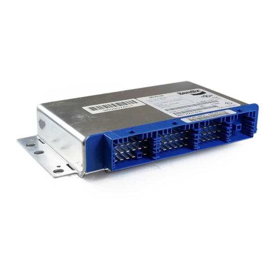
FIGURE 1 - EC-60
INTRODUCTION
The Bendix
EC-60
advanced controller is a member
®
™
of a family of electronic Antilock Braking System
(ABS) devices designed to help improve the braking
characteristics of air braked vehicles - including heavy and
medium duty buses, trucks, and tractors. ABS controllers
are also known as Electronic Control Units (ECUs).
Bendix
ABS uses wheel speed sensors, ABS pressure
®
modulator valves, and an ECU to control either four or
six wheels of a vehicle. The EC-60
individual wheel turning motion during braking and adjusts
or modulates the brake pressure at the wheel end. When
excessive wheel slip, or wheel lock-up is detected, the
EC-60
controller will activate the pressure modulator
™
valves to automatically reduce the brake pressure at one
or more of the wheel ends. By these actions, the ABS
system helps to maintain the vehicle's lateral stability and
steerability during heavy brake applications and during
braking on slippery surfaces.
In addition to the ABS function, advanced models of the
EC-60
controller provide an Automatic Traction Control
™
(ATC) feature. Bendix ATC can improve vehicle traction
during acceleration, and lateral stability while accelerating
through curves. ATC utilizes Engine Torque Limiting
(ETL) where the ECU communicates with the engine's
controller and/or Differential Braking (DB) where
individual wheel brake applications are used to improve
vehicle traction.
Advanced EC-60
controllers have a drag torque control
™
feature which reduces driven-axle wheel slip (due to
driveline inertia) by communicating with the engine's
controller and increasing the engine torque.
The EC-60
advanced model provides ABS-based stability
™
features referred to as ESP
ESP
is a registered trademark of DaimlerChrysler and is used by BCVS under
®
license from DaimlerChrysler.
ADVANCED CONTROLLER
™
controller monitors
™
Electronic Stability Program.
®
TABLE OF CONTENTS
General System Information
Introduction . . . . . . . . . . . . . . . . . . . . . . . . . . . . . . . . 1
Components . . . . . . . . . . . . . . . . . . . . . . . . . . . . . . . 2
ECU Mounting . . . . . . . . . . . . . . . . . . . . . . . . . . . . . 3
EC-60
Controller Hardware Configurations . . . . . . 3
™
EC-60
Controllers with PLC . . . . . . . . . . . . . . . . . . 3
™
Controller Inputs . . . . . . . . . . . . . . . . . . . . . 4
™
ABS Off-Road Switch and Indicator Lamp . . . . . . . . 4
Controller Outputs . . . . . . . . . . . . . . . . . . . . 5
™
Power-Up Sequence. . . . . . . . . . . . . . . . . . . . . . . . . 6
ABS Operation . . . . . . . . . . . . . . . . . . . . . . . . . . . . . 7
ATC Operation . . . . . . . . . . . . . . . . . . . . . . . . . . . . . 8
Advanced ABS with Stability . . . . . . . . . . . . . . . . . . . 9
Yaw Control. . . . . . . . . . . . . . . . . . . . . . . . . . . . . . . . 9
Dynamometer Test Mode . . . . . . . . . . . . . . . . . . . . . 9
Automatic Tire Size Calibration. . . . . . . . . . . . . . . . 10
ABS Partial Shutdown . . . . . . . . . . . . . . . . . . . . . . 10
System Reconfiguration
EC-60
Controller System Reconfiguration . . . . . . 11
™
Troubleshooting
General . . . . . . . . . . . . . . . . . . . . . . . . . . . . . . . . . . 12
Steering Angle Sensor Calibration . . . . . . . . . . . . . 13
Yaw Rate/Lateral Acceleration Calibration . . . . . . . 14
Diagnostic Trouble Codes. . . . . . . . . . . . . . . . . . . . 16
Using Hand-Held or PC-based Diagnostics . . . . . . 19
Diagnostic Trouble Code Troubleshooting Index . . 21
Trouble Code Tests . . . . . . . . . . . . . 22 - 37
Connectors . . . . . . . . . . . . . . . . . . . . . . . . . . . . . . . 38
Wiring . . . . . . . . . . . . . . . . . . . . . . . . . . . . . . . . 39-41
Wiring Schematics . . . . . . . . . . . . . . . . . . . . . . . . . 42
Glossary . . . . . . . . . . . . . . . . . . . . . . . . . . . . . . . . . 43
J1587 SID and FMI Codes . . . . . . . . . . . . . . . 44-47
The Bendix ESP system is an ABS-based stability system
that enhances vehicle stability by both reducing engine
throttle and by applying vehicle braking based on actual
vehicle dynamics. Accordingly, the ESP system is available
only on specific approved vehicle platforms after vehicle
application and development efforts and validation testing.
Only certain limited variations of an approved vehicle
platform are permitted without further validation of the ESP
system application.
ESP stability system consists of Yaw Control (YC) and Roll
Stability Program (RSP) features.
CAUTION
Even with ESP-equipped vehicles, the driver remains
responsible for ensuring vehicle stability during
operation.
PAGE
1
Advertisement
Table of Contents

Related Manuals for BENDIX EC-60 ABS-ATC ESP CONTROLLERS ADV


Summary of Contents for BENDIX EC-60 ABS-ATC ESP CONTROLLERS ADV
-
Page 1: Table Of Contents
J1587 SID and FMI Codes ....44-47 braking on slippery surfaces. In addition to the ABS function, advanced models of the The Bendix ESP system is an ABS-based stability system EC-60 controller provide an Automatic Traction Control ™... -
Page 2: Components
Valves (4, 5, or 6 depending on configuration) ROLL STABILITY PROGRAM (RSP) • Dash-mounted tractor ABS Indicator Lamp The Bendix Roll Stability Program (RSP), is an all-axle • Service brake relay valve ABS solution that helps reduce vehicle speed by reducing the engine's throttle and applying all vehicle brakes as •... -
Page 3: Ecu Mounting
Brake Demand Sensors (installed in the primary and secondary delivery circuits) • Load Sensor (typically installed in the suspension air bag) • An additional Modulator Valve (Bendix M-32 ® ™ FIGURE 6 - POWER LINE WITHOUT PLC SIGNAL M-32QR Pressure Modulator Valve) that controls ™... -
Page 4: Controller Inputs
J1939 ™ signal is an amplitude and frequency modulated signal. message to operate the lamp, e-mail ABS@bendix.com, Depending on the filtering and load on the power line, the specifying the ECU part number, or call 1-800-AIR-BRAKE PLC signal amplitude can range from 5.0mVp-p to 7.0 and speak to the Bendix TechTeam.) -
Page 5: Controller Outputs
Bendix M-32 and M-32QR Pressure ™ ® ™ ™ the lamp, e-mail ABS@bendix.com, specifying the ECU Modulator Valves (PMV) part number, or call 1-800-AIR-BRAKE and speak to the The Bendix M-32 and M-32QR pressure modulator ® ™... -
Page 6: Power-Up Sequence
™ communications message to operate the lamp, e-mail ABS System Power Application ABS@bendix.com, specifying the ECU part number, or call Status Indicators 1-800-AIR-BRAKE and speak to the Bendix TechTeam.) 2.0 2.5 3.0 (sec.) SAE J1708/J1587 Serial Communications Powered Vehicle ABS... -
Page 7: Abs Operation
™ lead to high levels of wheel slip at the drive axle wheels, the two steering axle brakes. This Bendix patented brake which can adversely affect vehicle stability. application control, called Modified Individual Regulation... -
Page 8: Atc Operation
3. When the dynamometer test mode is active. The dynamometer test mode is entered using the diagnostic ATC Functional Overview blink code switch or by using a diagnostic tool (such as Just as ABS improves vehicle stability during braking, Bendix ACom Diagnostics). ® ™... -
Page 9: Advanced Abs With Stability
Roll Stability Program Bendix RSP, an element of the overall ESP system, addresses rollover conditions. In the case of a potential roll event, the ECU will override the throttle and quickly apply brake pressure at all wheel ends to slow the vehicle combination. -
Page 10: Yaw Control
IMPORTANT SAFETY INFORMATION ABOUT THE BENDIX STABILITY SYSTEM ® ® ESP May Reduce The Vehicle Speed Automatically ESP can make the vehicle decelerate automatically. ESP can slow the vehicle with or without the operator applying the brake, and even when the throttle is being applied. -
Page 11: Dynamometer Test Mode
(e.g. visor labels, etc.) used to show in the memory. This process adapts the ABS and ATC that Bendix ESP was installed and make any necessary function to the vehicle. notations in the vehicle manual(s), so that drivers do... -
Page 12: Abs Partial Shutdown
ATC is disabled. ABS on the affected wheel is disabled. ABS ABS control settings, engine module communication etc. on all other wheels remains active. ESP is disabled. Many of these settings can be reconfigured using a hand held or PC-based software, such as the Bendix ACom ® ™... -
Page 13: General
2. Record the part number of the EC-60 Advanced ™ Controller. 8. Use only genuine Bendix replacement parts, ® components and kits. Replacement hardware, 3. Provide this information to your local OEM vehicle tubing, hose, fittings, etc. must be of equivalent service department to obtain a new ECU. -
Page 14: Steering Angle Sensor Calibration
Bendix is not able to validate the safe and achieved without pulling apart the connectors. reliable use of substitute or alternate components that may 7. - Page 15 Yaw Rate Sensor Calibration: a component approved for use with the Bendix Advanced The yaw rate sensor calibration can only be achieved via ABS system. However, replacement of brake demand the Advanced ABS ECU.
- Page 16 Troubleshooting: Blink Codes and Diagnostic Modes ECU DIAGNOSTICS BLINK CODES The EC-60 controller contains self-testing diagnostic Blink codes allow a technician to troubleshoot ABS ™ circuitry that continuously checks for the normal operation problems without using a hand-held or PC-based diagnostic of internal components and circuitry, as well as external tool.
-
Page 17: Diagnostic Modes
(See page 21 for a directory of communications are re-established. these codes.) All active trouble codes may also be retrieved using a hand-held or PC-based diagnostic tool, such as the Bendix ACom Diagnostics software. ®... - Page 18 Pressure Modulator Valves 4 Modulators Inactive trouble codes, and event history, may be retrieved and cleared by using a hand-held or PC-based diagnostic 5 Modulators 6 Modulators tool, such as the Bendix ACom Diagnostics software. ® ™ 4th Number ABS Configuration...
-
Page 19: Diagnostic Trouble Codes
9 pin diagnostic connector ™ diagnostic trouble code is properly corrected the first time, in the cab of the vehicle. An adapter cable (Bendix part additional troubleshooting may be necessary. Note: The number 801872) is available to connect the RDU to vehicles RDU is not capable of diagnosing ESP-specific diagnostic... -
Page 20: Connectors
EC-60 ABS ECU, the computer’s serial or parallel ™ Nexiq provides a Bendix application card for use with the port needs to be connected to the vehicle’s diagnostic ProLink tool. It can also be used to diagnose the EC-30 ™... - Page 21 Example: For a message sequence of: 3, 2 12, 4 For the first sequence go to page 22 and for the second sequence go to page 30. See Page 44 for Appendix A: J1587 SID and FMI Codes and Their Bendix Blink Code Equivalents...
- Page 22 Troubleshooting Diagnostic Trouble Codes: Wheel Speed Sensors 1st. Blink Location Code Left Steer Axle Sensor Right Steer Axle Sensor Left Drive Axle Sensor Right Drive Axle Sensor Left Additional Axle Sensor Right Additional Axle Sensor 2nd. Diagnostic Blink Trouble Code Code Description Repair Information Excessive...
- Page 23 Speed Sensor Repair Tests: 1. Take all measurements at ECU harness connector pins in order to check wire harness and sensor. Probe the connector carefully so that the terminals are not damaged. 2. Wheel speed sensor measurements should read: Location Measurement Sensor 1500 - 2500 Ohms...
- Page 24 Troubleshooting Diagnostic Trouble Codes: Pressure Modulator Valves 1st. Blink Location Code Left Steer Axle Right Steer Axle Left Drive Axle Right Drive Axle Left Additional Axle Right Additional Axle Trailer PMV 2nd. Diagnostic Blink Trouble Code Code Description Repair Information Release Verify no continuity between PMV leads and ground.
- Page 25 Pressure Modulator Valve Repair Tests: 1. Take all measurements at ECU harness connector pins in order to check wire harness and PMV. Probe the connector carefully so that the terminals are not damaged. 2. Pressure modulator resistance should read: Location Measurement Release to Common 4.9 to 5.5 Ohms...
- Page 26 Troubleshooting Diagnostic Trouble Codes: Traction Control Valves 1st. Blink Location Code Drive Axle Traction Control Valve Steer Axle Traction Control Valve 2nd. Diagnostic Blink Trouble Code Code Description Repair Information TCV Solenoid Verify 7 to 19 ohms between TCV and TCV common. Verify no continuity between Shorted to TCV leads and ground.
- Page 27 Troubleshooting Diagnostic Trouble Codes: Power Supply 1st. Blink Location Code Power Supply 2nd. Diagnostic Blink Trouble Code Code Description Repair Information Battery Voltage Measure battery voltage under load. Check vehicle battery and associated components. Too Low Check for damaged wiring. Check for damaged or corroded connectors and connections. Battery Voltage Measure battery voltage under load.
-
Page 28: Wiring
Troubleshooting Diagnostic Trouble Codes: J1939 Serial Communications 1st. Blink Location Code J1939 2nd. Diagnostic Blink Trouble Code Code Description Repair Information J1939 Serial Link Loss of communications between the EC-60 controller and other devices connected ™ to the J1939 link. Check for damaged or reversed J1939 wiring. Check for corroded or damaged connectors. - Page 29 Troubleshooting Diagnostic Trouble Codes: 1st. Blink Location Code 2nd. Diagnostic Blink Trouble Code Code Description Repair Information ECU (02) ECU (10) ECU (11) ECU (12) ECU (13) 2-24: Check for damaged or corroded connectors. Check for damaged wiring. ECU (14) Clear trouble codes.
- Page 30 Troubleshooting Diagnostic Trouble Codes: Miscellaneous 1st. Blink Location Code Miscellaneous 2nd. Diagnostic Blink Trouble Code Repair Information Code Description Stop Lamp Switch ECU has not detected the presence of the stop lamp switch since ignition power was applied (note that stop lamp Not Detected switch input may be applied to the EC-60 controller using either hardwire input or J1939).
- Page 31 Miscellaneous Troubleshooting (continued) For all tests below, take all measurements at ECU Retarder Relay harness connector pins in order to check wire harness 1. Measure resistance between retarder disable output of and sensor. Probe the connector carefully so that the EC-60 controller and voltage / ground.
- Page 32 Troubleshooting Diagnostic Trouble Codes: Steering Angle Sensor (SAS-60 sensor) ™ 1st. Blink Location Code Steering Angle Sensor 2nd. Diagnostic Blink Trouble Code Repair Information Code Description SAS has not been calibrated. Perform SAS calibration procedure. SAS Not Calibrated SAS calibration procedure is underway. SAS Calibration in Progress SAS signal incorrect.
- Page 33 1. Measure resistance between input voltage and ground at the sensor wiring harness connector. 6. To test the Steering Angle Sensor, ACom V4.0 is required. Using Bendix ACom V4.0, select the Test Measurement “Component Test” option, followed by the “ESP Test”...
- Page 34 Troubleshooting Diagnostic Trouble Codes: Yaw Rate Sensor (YRS) 1st. Blink Location Code Yaw Rate Sensor 2nd. Diagnostic Blink Trouble Code Repair Information Code Description YRS Signal YRS signal incorrect. Verify proper installation of the YRS. Verify proper wiring between the ECU and the YRS. Out of Range Check YRS output.
- Page 35 1. Measure resistance between input voltage and ground at the sensor wiring harness connector. 6. To test the Yaw Rate Sensor, ACom V4.0 is required. Using Bendix ACom V4.0, select the “Component Test” option, followed by the “ESP Test” option. The following Test...
- Page 36 Troubleshooting Diagnostic Trouble Codes: Lateral Acceleration Sensor (LAS) 1st. Blink Location Code Lateral Acceleration Sensor 2nd. Diagnostic Blink Trouble Code Repair Information Code Description LAS signal incorrect. Verify proper installation of the YRS/LAS. Verify proper wiring LAS Signal between the ECU and the YRS/LAS. Check YRS/LAS output. Perform LAS calibration Out of Range procedure.
- Page 37 Troubleshooting Diagnostic Trouble Codes Brake Demand/Load Sensors 1st. Blink Location Code Brake Demand/Load Sensors 2nd. Diagnostic Blink Trouble Code Repair Information Code Description PS1 Open or Check wiring between Brake Demand Sensor (primary brake circuit) and ECU. Verify Shorted operation of pressure sensor. PS2 Open or Check wiring between Brake Demand Sensor (secondary brake circuit) and ECU.
- Page 38 EC-60 Controller Wire Harness Connector Part ™ Numbers and Pin Assignments: ADVANCED CAB CONNECTOR CONNECTOR CONNECTOR CONNECTOR Advanced Cab Model EC-60 Controller ™ Advanced cab models utilize four AMP connectors for wire harness connections. X1 Connector Pin Assignments Pin Designation Pin Designation Pin Designation Ground...
- Page 39 Troubleshooting: Wiring ABS/ATC WIRING WARNING: All wires must be carefully routed to avoid contact with rotating elements. Wiring must be properly ECU Wiring Harness Connectors secured approximately every 6 to 12 inches using UV The Advanced EC-60 controller is designed to interface stabilized, non-metallic hose clamps or bow-tie cable ties ™...
- Page 40 ABS Component Connector Wire Wire Seal/ Terminal Terminal Terminal Plug Lock Crimp Tool Controller Harness 927768-9 17-Way AMP 1 - 2.5 mm MCP 2.8 (X1) X1-12 & 18 967634 1718091-1 Controller Harness 18-Way AMP 968874 MCP 2.8 (X2) 8-968974-1 2.5 - 4 mm Controller Harness 15-Way AMP...
- Page 41 ™ Wheel Speed Sensor Wiring Route sensor wiring coming out of the wheel ends away Bendix does not recommend using standard tie-wraps to from moving brake components. Sensor wiring needs to secure wiring harnesses directly to rubber air lines. This...
-
Page 42: Wiring Schematics
Troubleshooting: Wiring Schematic PMV_TR_REL PMV_TR_CMN PMV_TR_HLD PS_SIG PS_SIG PS_SPL PS_CMN PS_SIG CAN_SEN_SPL CAN_SEN_CMN CAN_SEN_HI CAN_SEN_LO TCV_SA_CMN TCV_SA PMV_AL_REL PMV_AL_CMN PMV_AL_HLD PMV_AR_REL PMV_AR_CMN PMV_AR_HL WSS_AL- WSS_AL+ WSS_AR- WSS_AR+ DIFF OUTPUT LAMP STOP WSS_SL- WSS_SL+ WSS_SR- WSS_SR+ PMV_SL_REL PMV_SL_CMN PMV_SL_HLD PMV_SR_REL PMV_SR_CMN PMV_SR_HL PMV_DL_REL PMV_DL_CMN... -
Page 43: Glossary
Glossary ABS — Antilock Brake System. J1587 — The SAE heavy duty standard diagnostic data link. ABS Event — Impending wheel lock situation that causes the J1708 — An SAE standard which defines the hardware and ABS controller to activate the modulator valve(s). software protocol for implementing 9600 baud heavy vehicle data links. -
Page 44: J1587 Sid And Fmi Codes
Appendix A: J1587 SID and FMI Codes and Their Bendix Blink Code Equivalents General Bendix Blink Code Diagnostic Trouble Code Description (J1587) (J1587) Equivalent(s) (1st Digit) (2nd Digit) - ..-..No DTCs ......1 ..1 ..No DTCs 1. - Page 45 General Bendix Blink Code Diagnostic Trouble Code Description (J1587) (J1587) Equivalent(s) (1st Digit) (2nd Digit) 53 ..4 ..Pressure Modulator Valve DTCs ..17 ..1 ..AA Right PMV REL Solenoid Shorted to Ground 66 .
- Page 46 General Bendix Blink Code Diagnostic Trouble Code Description (J1587) (J1587) Equivalent(s) (1st Digit) (2nd Digit) 22 ..7 ..Miscellaneous DTCs ....12 ..11 ..Wheel Speed Sensors Reversed on an Axle 102.
- Page 47 General Bendix Blink Code Diagnostic Trouble Code Description (J1587) (J1587) Equivalent(s) (1st Digit) (2nd Digit) 103..2 ..Yaw Rate Sensor DTCs ... . . 22 ..12 ..YRS Plausibility Check (Ref Yaw Rate) 103.
- Page 48 BW2429 ©2005 Bendix Commercial Vehicle Systems LLC • All Rights Reserved • 5/05 • Printed in U.S.A.
Need help?
Do you have a question about the EC-60 ABS-ATC ESP CONTROLLERS ADV and is the answer not in the manual?
Questions and answers