Sign In
Upload
Download
Table of Contents
Contents
Add to my manuals
Delete from my manuals
Share
URL of this page:
HTML Link:
Bookmark this page
Add
Manual will be automatically added to "My Manuals"
Print this page
×
Bookmark added
×
Added to my manuals
Manuals
Brands
Deif Manuals
Measuring Instruments
BW192
Installation and commissioning manual
Deif BW192 Installation And Commissioning Manual
Illuminated indicators
Hide thumbs
1
Table Of Contents
2
3
4
5
6
7
8
9
10
11
12
13
14
15
16
17
18
19
20
21
22
23
24
25
26
27
28
29
30
31
32
33
34
35
36
37
38
39
page
of
39
Go
/
39
Contents
Table of Contents
Bookmarks
Table of Contents
Table of Contents
XL Wiring and Installation
Wiring
Analogue Input Indicators
Rudder Potentiometer Analogue Indicator
Dimmer Setup for Analogue Indicators
Dual Canopen Indicators
Dimmer Setup for Dual Canopen Indicators
Scan Input Indicators
Dimmer Setup for Scan Indicators
Dimensions and Panel Cutout
XL Dimensions
XL Panel Cutout
Mounting XL Indicators
BW Wiring and Installation
Wiring
Dimmer Wiring
Cable Glands
Dimensions and Drilling Template
BW Dimensions
Drilling Template
Mounting BW Indicators
BRW-2 Wiring and Installation
Wiring
Overview
Analogue Input Terminal Overview
Canopen Input Terminal Connections
Dimmer Wiring
Dimensions and Drilling Template
Brw-2
Drilling Template
Replacement of XL192 Indicator in BRW-2
Overview
Replacement Instructions
Adjustment Help for Analogue Input Indicators
Commissioning
Commissioning Preparation
Commissioning Analogue Indicators
Special 4 to 20 Ma Functionality
Adjustment of Single Analogue Input Indicators
Adjustment Functionality
Out of Range Definition
Commissioning Scan Indicators
Start Setup Mode
Synchronise XL Indicators over CAN
Replacing Indicators in a Calibrated System
Setup Indicators Without 360° Scales
Setup Indicators with 360° Scales
Commissioning Single and Dual Canopen Indicators
Termination of the Canopen Line
Error Handling
Analogue 240° Indicators
Analogue 360° Indicators
CAN 240° Indicators
CAN 360° Indicators
Appendix A - Pointer Position Examples
Appendix B: Pointer Positions Based on Input
Standard Analogue Indicators
Rudder Indicators
Standard Azimuth Indicators
Analogue SIN/COS Azimuth Indicators
Advertisement
Quick Links
1
Xl Wiring and Installation
2
Wiring
3
Analogue Input Indicators
4
Error Handling
Download this manual
XL, BW, BRW-2
Illuminated indicators
Installation and commissioning guide
Table of
Contents
Previous
Page
Next
Page
1
2
3
4
5
Advertisement
Table of Contents
Need help?
Do you have a question about the BW192 and is the answer not in the manual?
Ask a question
Questions and answers
Related Manuals for Deif BW192
Measuring Instruments Deif BRW-2 Quick Manual
(2 pages)
Measuring Instruments Deif XL Installation And Commissioning Manual
Illuminated indicators (39 pages)
Measuring Instruments Deif BRW-2 Quick Manual
Bridge wing indicator (4 pages)
Measuring Instruments Deif BRW-2 Quick Manual
Bridge wing indicator (4 pages)
Measuring Instruments Deif BW Installation And Commissioning Manual
Illuminated indicators (39 pages)
Measuring Instruments Deif BW144 Installation And Commissioning Manual
Illuminated indicators (39 pages)
Measuring Instruments Deif WSI User Manual
Ultrasonic wind (19 pages)
Measuring Instruments Deif MIC-2 MKII Quick Start Manuals
Multi-instrument communication (14 pages)
Measuring Instruments Deif XDi Series Designers Handbook
Flexible display indicator (206 pages)
Measuring Instruments Deif MIB 7000 Installation Instructions And Reference Handbook
Multi-instrument (50 pages)
Measuring Instruments Deif EPN-110DN Installation And Start-Up Instructions
Electronic potentiometer (4 pages)
Measuring Instruments Deif MIB 8000 Designers Handbook
Multi-instrument (23 pages)
Measuring Instruments Deif ADL-111Q96/xxVDC Series Installation & Operation Instructions
Insulation monitor (8 pages)
Measuring Instruments Deif MIC-2 MKII DIN Quick Start Manual
Multi-instrument communication (10 pages)
Measuring Instruments Deif MIQ96 User Manual
Multi-instrument (51 pages)
Measuring Instruments Deif MIQ96-2 User Manual
Multi-instrument (7 pages)
Summarization of Contents
Overview of DEIF Illuminated Indicators
Legal Information and Safety
Covers legal notices, disclaimers, copyright, and safety precautions.
Package Contents Summary
Details the items included in the indicator package for various models.
XL Series Indicator Wiring and Installation Guide
XL Wiring Connections
Detailed wiring diagrams and terminal connections for various XL indicator input types.
XL Dimensions and Panel Cutout
Provides physical dimensions and panel cutout specifications for XL indicator models.
XL Indicator Mounting Procedure
Instructions for mounting XL indicators using fixing clamps and gaskets.
BW Series Indicator Wiring and Installation Guide
BW Wiring and Dimmer Setup
Wiring instructions, dimmer wiring, and cable gland information for BW indicators.
BW Dimensions and Drilling Template
Specifies dimensions and provides drilling templates for BW indicator installation.
BW Indicator Mounting
Guidance on mounting BW indicators using the provided bracket.
BRW-2 Indicator Wiring and Installation
BRW-2 Wiring Overview
Details terminal connections for analogue and CANopen inputs and dimmer wiring.
BRW-2 Dimensions and Drilling Template
Provides physical dimensions and drilling template for the BRW-2 indicator.
BRW-2 XL192 Indicator Replacement
Procedure for replacing an XL192 indicator within the BRW-2 housing.
Indicator Commissioning Procedures
Commissioning Preparation and Analogue Indicators
Pre-commissioning steps and detailed procedures for analogue indicator setup.
sCAN and CANopen Indicator Commissioning
Commissioning steps for sCAN and CANopen indicators, including CANopen termination.
Indicator Error Handling
Troubleshooting guide for various indicator status errors and fault conditions.
Appendix A: Analogue Pointer Position Examples
Appendix B: Pointer Positions Based on Input Signals
Standard Analogue Indicator Input Positions
Maps input signals to pointer positions for standard analogue indicators.
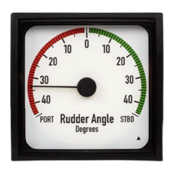
Rudder Indicator Input Positions
Details pointer positions for rudder indicators based on input signals.
Standard Azimuth Indicator Input Positions
Maps input signals to pointer positions for standard azimuth indicators.
Analogue SIN/COS Azimuth Indicator Input Positions
Details pointer positions for SIN/COS azimuth indicators based on input signals.
Table of Contents
Print
Rename the bookmark
Delete bookmark?
Delete from my manuals?
Login
Sign In
OR
Sign in with Facebook
Sign in with Google
Upload manual
Upload from disk
Upload from URL
Need help?
Do you have a question about the BW192 and is the answer not in the manual?
Questions and answers