Table of Contents
Advertisement
Advertisement
Table of Contents

Related Manuals for Deif BW


Summarization of Contents
1. Overview
1.1 Legal information and safety
Details legal information and safety precautions for the indicators and third-party equipment.
1.2 Package contents
Describes the items included in the package for XL, BW, and BRW-2 indicators.
2. XL wiring and installation
2.1 Wiring
Covers wiring details for XL indicators, including terminal connections for various input types.
2.1.1 Analogue input indicators
Details terminal connections for analogue input indicators, covering voltage and current inputs.
2.1.2 Rudder potentiometer analogue indicator
Explains special input for direct connection to rudder potentiometers and their adjustment.
2.1.3 Dimmer setup for analogue indicators
Illustrates methods for arranging local dimmers on XL indicators using potentiometers.
2.1.4 Dual CANopen indicators
Details terminal connections for dual CANopen indicators, including CAN bus and illumination.
2.1.5 Dimmer setup for dual CANopen indicators
Explains illumination control for dual CANopen indicators via CANopen line or dimmer terminals.
2.1.6 sCAN input indicators
Provides pinout and function details for sCAN input indicators, including switch/button use.
2.1.7 Dimmer setup for sCAN indicators
Describes illumination control for sCAN indicators using a dimmer line or external potentiometer.
2.2 Dimensions and panel cutout
Provides dimensional data and panel cutout specifications for XL indicators.
2.2.1 XL dimensions
Lists dimensions for XL72, XL96, XL144, and XL192 indicators in millimeters and inches.
2.2.2 XL panel cutout
Details panel cutout dimensions and tolerances for XL72 and XL96 indicators.
2.3 Mounting XL indicators
Explains mounting XL indicators using fixing clamps, gaskets, and standard DIN procedures.
3. BW wiring and installation
3.1 Wiring
Covers BW wiring, access to terminals via bulkhead box, and identical wiring to XL instruments.
3.1.1 Dimmer wiring
Explains the function of the built-in potentiometer for local dimmer control on BW indicators.
3.1.2 Cable glands
Describes the two PG cable glands (PG9, PG16) equipped on the bulkhead box for BW units.
3.2 Dimensions and drilling template
Provides dimensional data and drilling template information for BW indicators.
3.2.1 BW dimensions
Lists dimensions for BW144 and BW192 indicators in millimeters and inches.
3.2.2 Drilling template
Provides a drilling template for mounting BW indicators, noting it is a guideline.
3.3 Mounting BW indicators
Explains how to mount BW indicators using the bracket and screws, with notes on asymmetry.
4. BRW-2 wiring and installation
4.1 Wiring
Overview of BRW-2 wiring, including cable dimensions, PG glands, and ESD protection.
4.1.1 Overview
General information on BRW-2 wiring, ESD protection, and cable gland specifications.
4.1.2 Analogue input terminal overview
Details terminal connections for analogue input on BRW-2, including supply, input, and illumination.
4.1.3 CANopen input terminal connections
Details terminal connections for CANopen input on BRW-2, including CAN lines and supply.
4.1.4 Dimmer wiring
Explains dimmer wiring options for BRW-2, including built-in and external dimmers.
4.2 Dimensions and drilling template
Provides dimensional data and drilling template for BRW-2 indicators.
4.2.1 BRW-2
Lists dimensions for BRW-2 and notes on dimmer box/kit availability.
4.2.2 Drilling template
Provides the drilling template for BRW-2 indicators, noting it is a guideline.
4.3 Replacement of XL192 indicator in BRW-2
Details the relevance and overview for replacing an XL192 indicator within a BRW-2 unit.
4.3.1 Overview
Provides an overview for replacing BRW-1 products with XL192 indicators, including connections.
4.3.2 Replacement instructions
Lists step-by-step instructions for replacing an XL192 indicator inside a BRW-2 unit.
4.3.3 Adjustment help for analogue input indicators
Offers guidance on adjusting analogue input indicators when the XL192 is removed for adjustment.
5. Commissioning
5.1 Commissioning preparation
Steps to prepare for commissioning, including waiting for class surveyor approval.
5.2 Commissioning analogue indicators
Details the commissioning process for analogue indicators, including LED status and error conditions.
5.2.1 Special 4 to 20 mA functionality
Explains the special feature for changing pointer deflection in 4 to 20 mA single versions.
5.2.2 Adjustment of single analogue input indicators
Guides on adjusting zero and maximum points for single analogue input indicators.
5.2.3 Adjustment functionality
Details how to use Potentiometer A (max) and B (zero) for different XL indicator types.
5.2.4 Out of range definition
Defines the conditions under which the indicator pointer moves to the 'out-of-range' position.
5.3 Commissioning sCAN indicators
Describes basic settings for sCAN indicators, including zero, min, max, and pointer movement.
5.3.1 Start setup mode
Explains how to use the CAN 2 line as a set-up selector for sCAN indicators.
5.3.2 Synchronise XL indicators over CAN
Details how XL indicators listening to the same CAN ID synchronize automatically.
5.3.3 Replacing indicators in a calibrated system
Notes that recalibration is needed when replacing indicators in a calibrated system.
5.3.4 Setup indicators without 360° scales
Guides on setting zero position for indicators without 360° scales.
Set minimum position
Instructions for setting the minimum scale value for indicators without 360° scales.
Set maximum position
Instructions for setting the maximum scale value for indicators without 360° scales.
Changing pointer rotation
Explains how to change pointer rotation from CW to CCW by adjusting input/sensor values.
5.3.5 Setup indicators with 360° scales
Guides on setting zero position, CCW rotation, and CW rotation for 360° scale indicators.
5.4 Commissioning Single and Dual CANopen indicators
Details commissioning for CANopen indicators, including LED status and CAN communication.
5.4.1 Termination of the CANopen line
Explains the importance of CANopen line termination for safe communication and EMC.
5.5 Error handling
Details error states, LED indications, and pointer behavior for various indicator types.
5.5.1 Analogue 240° indicators
Lists error states, LED, pointer behavior, and remarks for analogue 240° indicators.
5.5.2 Analogue 360° indicators
Lists error states, LED, pointer behavior, and remarks for analogue 360° indicators.
5.5.3 CAN 240° Indicators
Lists error states, LED, pointer behavior, and remarks for CAN 240° indicators.
5.5.4 CAN 360° indicators
Lists error states, LED, pointer behavior, and remarks for CAN 360° indicators.
6. Appendix A - Pointer position examples
Analogue Pitch Indicator Input Examples
Shows pointer positions for 4-20mA analogue pitch indicators at minimum, middle, and maximum inputs.
Analogue Pitch Indicator Error Examples
Illustrates pointer positions for analogue pitch indicators under error conditions.
7. Appendix B: Pointer positions based on input
7.1 Standard analogue indicators
Details pointer positions for standard analogue indicators with different input types (mA, V).
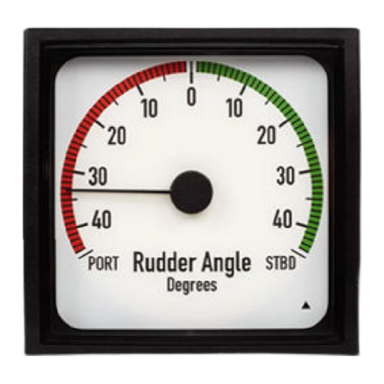
7.2 Rudder indicators
Explains pointer positions for rudder indicators, including CW/CCW configurations.
7.3 Standard azimuth indicators
Details pointer positions for standard azimuth indicators with different input types and EM settings.
7.4 Analogue SIN/COS azimuth indicators
Provides pointer positions for Analogue SIN/COS azimuth indicators with different input types and EM settings.
Need help?
Do you have a question about the BW and is the answer not in the manual?
Questions and answers