Table of Contents
Advertisement
Quick Links
Installation/operation instructions
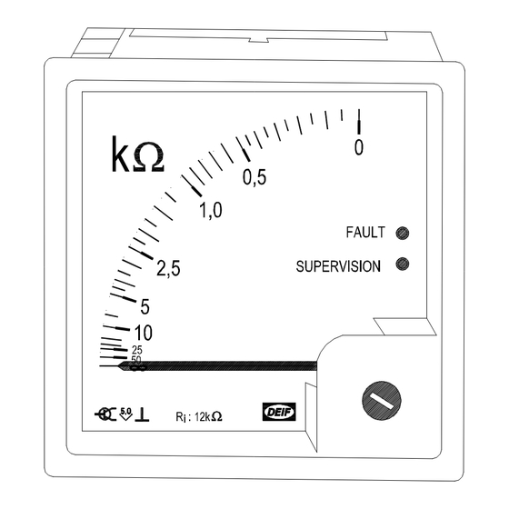
Insulation monitor type ADL-111Q96/xxVDC
4189330017B (UK)
•
Monitoring of insulation resistance on a DC network
•
Working voltage 24V, 110V or 220V DC
•
Measuring range 50...0kΩ, 250...0kΩ, 500...0kΩ
•
Alarm on exceeding the adjusted set point
•
DC auxiliary supply or self-powered
•
Balanced insulation error included
DEIF A/S
Frisenborgvej 33, DK-7800 Skive
Denmark
Tel.:
(+45) 9614 9614
Fax:
(+45) 9614 9615
E-mail:
deif@deif.com
Advertisement
Table of Contents

Subscribe to Our Youtube Channel
Related Manuals for Deif ADL-111Q96/xxVDC Series


Summary of Contents for Deif ADL-111Q96/xxVDC Series
- Page 1 Measuring range 50...0kΩ, 250…0kΩ, 500…0kΩ • Alarm on exceeding the adjusted set point • DC auxiliary supply or self-powered • Balanced insulation error included DEIF A/S Tel.: (+45) 9614 9614 Frisenborgvej 33, DK-7800 Skive Fax: (+45) 9614 9615 Denmark E-mail:...
- Page 2 Switchboard test arrangement DC Source TEST Test Instrument shown as Instrument resistance self powered Relay contact 1,3,2 110V Supply on No alarm Alarm 220V recommended values Tel.: (+45) 9614 9614 • Fax: (+45) 9614 9615 • E-mail: deif@deif.com Page 2 of 7...
- Page 3 Installation/operation instructions ADL-111Q96/xxVDC Note If an earth fault is present at the positive and the negative conductor at the same time, the resulting value of the parallel insulation error is indicated on the instrument. This is also the case if the earth fault at the positive and the negative conductor has exactly the same size, e.g.
- Page 4 Sufficient care must be taken to protect the PCB against static discharges during the configuration. Once the unit is installed and connected, these precautions are no longer necessary. Tel.: (+45) 9614 9614 • Fax: (+45) 9614 9615 • E-mail: deif@deif.com Page 4 of 7...
- Page 5 Installation/operation instructions ADL-111Q96/xxVDC Configuration of the max. leakage capacitor (stray earth capacitance) Normally, the leakage capacitor is a phenomenon based on the cables in the IT power network. When the cables are mounted close to the metal structure, e.g. the hull of the ship, a capacitive coupling is unavoidable.
- Page 6 SUPERVISION is lit when the unit is connected to auxiliary supply and no insulation error below the set point is detected. Tel.: (+45) 9614 9614 • Fax: (+45) 9614 9615 • E-mail: deif@deif.com Page 6 of 7...
- Page 7 Installation/operation instructions ADL-111Q96/xxVDC The red LED indicator marked FAULT is illuminated, if an insulation error below the set point is detected. If the voltage exceeds the max. allowable value, e.g. 31.2V for the 24V version, the indication on the instrument will be infinite and the green LED starts flashing.
Need help?
Do you have a question about the ADL-111Q96/xxVDC Series and is the answer not in the manual?
Questions and answers