Table of Contents
Advertisement
Quick Links
User's manual
Multi-instrument type MIQ96
4189320005D (UK)
•
All 1- or 3-phase AC measurements (RMS) in one
unit:
- U
RMS
- P, Q, S, PF (cos
- kWh, kvarh, kVA
- MD, THD
•
Programmable CT and VT ratio
•
Programmable connections 1W, 1W3, 2W3, 1W4, 3W4
•
2 impulse outputs for kWh import, kvarh import (option)
•
Serial output (option)
DEIF A/S
Frisenborgvej 33, DK-7800 Skive Fax:
Denmark
, I
, f
RMS
ϕ
)
Tel.:
(+45) 9614 9614
(+45) 9614 9615
E-mail: deif@deif.com
Advertisement
Table of Contents

Subscribe to Our Youtube Channel
Related Manuals for Deif MIQ96


Summary of Contents for Deif MIQ96
- Page 1 User’s manual Multi-instrument type MIQ96 4189320005D (UK) • All 1- or 3-phase AC measurements (RMS) in one unit: ϕ - P, Q, S, PF (cos - kWh, kvarh, kVA - MD, THD • Programmable CT and VT ratio • Programmable connections 1W, 1W3, 2W3, 1W4, 3W4 •...
-
Page 2: Table Of Contents
Clock (setting of real time clock) ................45 17.9 Display (setting of display parameters)..............46 17.10 Language (setting of language) ................46 Password ......................47 Technical data ....................49 Page 2 of 51 Tel.: (+45) 9614 9614 • Fax: (+45) 9614 9615 • E-mail: deif@deif.com... -
Page 3: Warnings, Regular Information And Remarks Referring To Ce-Marking
If any doubt comes up concerning the installation or use of the system, on which the MIQ96 is to be used for measurement, the person responsible for the power installation should be contacted. -
Page 4: Options
ϕ • • • • ϕ • • • • • • • • • • • • • • • • • • Page 4 of 51 Tel.: (+45) 9614 9614 • Fax: (+45) 9614 9615 • E-mail: deif@deif.com... - Page 5 User’s manual, multi-instrument MIQ96 Parameter Connection type • • • • • • • • • • • • • • • • • • • • • cosϕ • • cosϕ • • cosϕ • • • • •...
-
Page 6: Measured Parameters
Power factor cosϕ , cosϕ , cosϕ , cosϕ THD (Total harmonic distortion) THD (I Frequency Integrated / maximum demands Maximum demand Energy , varh Page 6 of 51 Tel.: (+45) 9614 9614 • Fax: (+45) 9614 9615 • E-mail: deif@deif.com... -
Page 7: Display And Key-Pads
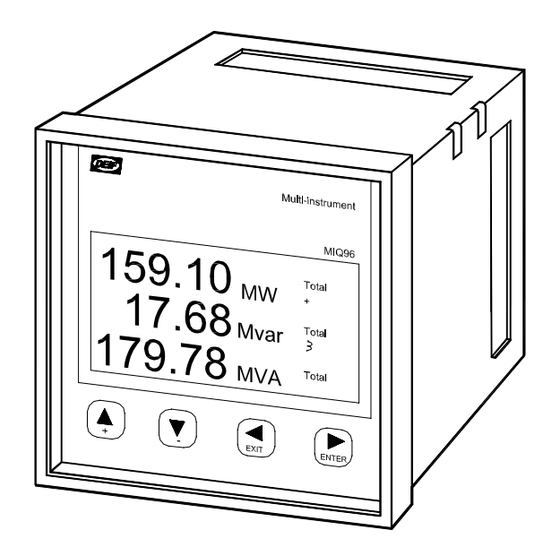
User’s manual, multi-instrument MIQ96 6. Display and key-pads The graphic LCD with yellow/green backlight is used for presentation of measured values and for displaying of the chosen function during set-up. Up arrow key. Up through the main menus. + increases a value in the menu ”Setting”. -
Page 8: Menus
If the password function is deactivated, the display for entering of password will not appear and access will be obtained directly. ENTER PASSWORD: **** Page 8 of 51 Tel.: (+45) 9614 9614 • Fax: (+45) 9614 9615 • E-mail: deif@deif.com... - Page 9 User’s manual, multi-instrument MIQ96 4189320005D (UK)
- Page 10 Page 10 of 51 Tel.: (+45) 9614 9614 • Fax: (+45) 9614 9615 • E-mail: deif@deif.com...
- Page 11 User’s manual, multi-instrument MIQ96 4189320005D (UK)
- Page 12 SETTING Page 12 of 51 Tel.: (+45) 9614 9614 • Fax: (+45) 9614 9615 • E-mail: deif@deif.com...
- Page 13 User’s manual, multi-instrument MIQ96 4189320005D (UK)
-
Page 14: Display Of Measuring Quantities For Connection 1W (1B)
Display of measuring quantities for connection 1W (1b) The following displays appear. Page 14 of 51 Tel.: (+45) 9614 9614 • Fax: (+45) 9614 9615 • E-mail: deif@deif.com... - Page 15 User’s manual, multi-instrument MIQ96 4189320005D (UK)
- Page 16 SETTING Page 16 of 51 Tel.: (+45) 9614 9614 • Fax: (+45) 9614 9615 • E-mail: deif@deif.com...
-
Page 17: Watt And Var Meters
User’s manual, multi-instrument MIQ96 8. Watt and var meters Displaying of measuring energy Pictures of the measured energy are identical for all kinds of grid connections. See section 16.2 page 31. Please notice that an indicator is flashing just to the right of the counter number when the counter is active. -
Page 18: Measuring Of Energy
4 counters for kWh and kvarh. The direction of energy is identical for all other connections. The consideration of import and export of energy. Consumer Generator Import Export Page 18 of 51 Tel.: (+45) 9614 9614 • Fax: (+45) 9614 9615 • E-mail: deif@deif.com... - Page 19 The function of the 4 counters, according to the displacement between voltage and current, is illustrated in the figure below. If the MIQ96 has relay output/outputs (see section 16.5 page 34), relay output 1 is corresponding to counter 3 (import kWh) and relay output 2 is corresponding to counter 4 (import kvarh).
-
Page 20: Maximum Demands (Md)
The MIQ96 displays the present or “dynamic” maximum demand (value below “PRESENT MD”). The MIQ96 also stores the maximum demand value since last reset and its corresponding time stamp, visible either from the MIQ96 display or remote communications link (value below “MD at DD.MM HH:MM”). -
Page 21: Thermal Demand
User’s manual, multi-instrument MIQ96 Thermal demand The thermal demand option will provide an exponential thermal characteristic, based on the bimetal element principle. Maximum demand and the time of its occurrence are stored in the unit. The period (Time C.) can be set in the range 1 to 255 minutes. -
Page 22: Fixed Window
Present MD and MD peak: Reset at time 0 min. FIXED INTERVAL Time C. 9 10 11 12 13 14 15 16 17 18 19 20 Min. Present MD MD peak Input Page 22 of 51 Tel.: (+45) 9614 9614 • Fax: (+45) 9614 9615 • E-mail: deif@deif.com... -
Page 23: Sliding Window
User’s manual, multi-instrument MIQ96 Sliding window The sliding window technique allows the user to divide the time period into a number of sub-periods. The average demand value over the demand total period is displayed, however, after the initial demand period has expired, the demand value will be updated by the addition of a further sub-period, thus creating a “sliding window”... -
Page 24: Display Of Current
The multi-instrument uses a true RMS (Root Mean Square) measurement technique which provides accurate measurement with harmonics present up to the 15 harmonic. ∞ ∑ • Page 24 of 51 Tel.: (+45) 9614 9614 • Fax: (+45) 9614 9615 • E-mail: deif@deif.com... -
Page 25: Display Of Voltage
User’s manual, multi-instrument MIQ96 11. Display of voltage All connections of the MIQ96, except in the 3-wire mode (1W3 and 2W3), measure the true RMS value of the phase voltages (U connected to the unit (only U for 1W connection). -
Page 26: Voltage Thd (Total Harmonic Distortion)
Calculation of P Reactive power: − Calculation of Q 1, 2, 3 Calculation of Q Apparent power: Calculation of S 1, 2, 3 Calculation of S Page 26 of 51 Tel.: (+45) 9614 9614 • Fax: (+45) 9614 9615 • E-mail: deif@deif.com... - Page 27 When displaying reactive power, a coil symbol indicates an inductive load while a capacitor symbol indicates a capacitive load (see section 13 page 28). All the available power parameters can be viewed using either the MIQ96 display or the remote communications link. 4189320005D (UK)
-
Page 28: Display Of Power Factor Pf (Cos Φ) And Frequency
14. Display of real time clock The MIQ96 is provided with a built-in real time clock. It is intended for registration of time of the occurrence of MDs, and for synchronisation of the time interval. -
Page 29: Display Of The Menu "Setting
User’s manual, multi-instrument MIQ96 15. Display of the menu “Setting” In the menu “Setting” the software version number is displayed when the left arrow key is pressed. The id-number of this instrument is stated above the software version number. This number is also visible on the label behind the protection lid for terminals. -
Page 30: Installation
Professionals must handle these areas. DEIF does not take on responsibility for the use and installation. If any doubt comes up concerning the installation or use of the system, on which the MIQ96 is to be used for measurement, the person responsible for the power installation should be contacted. -
Page 31: Electrical Installation
User’s manual, multi-instrument MIQ96 16.2 Electrical installation Connection for measuring voltage and measuring current: Choose one of the connections from the figures below and make the connection according to this for input voltage and input current. Consumption for voltage and current input - see “Technical data” section 19 page 49. - Page 32 Figure 16.2.4 1W4 connection (4b) Figure 16.2.5 3W4 connection (4u) Page 32 of 51 Tel.: (+45) 9614 9614 • Fax: (+45) 9614 9615 • E-mail: deif@deif.com...
-
Page 33: Connection For Aux. Supply
User’s manual, multi-instrument MIQ96 16.3 Connection for aux. supply Make the connection for aux. supply (see figure 16.5 page 34). AC: Line in the left terminal and neutral in the right. DC: + in the left terminal and – in the right. -
Page 34: Connection For Relay Outputs (Option)
Note: The set-up for kWh import and kvarh import counters for relay 1 and 2 respectively can only be changed via communication. Figure 16.5 Page 34 of 51 Tel.: (+45) 9614 9614 • Fax: (+45) 9614 9615 • E-mail: deif@deif.com... -
Page 35: Setting
“Language” is displayed. Push the key and ”English” will appear below ”Language”. Push the key and ”Set” will appear. Now the MIQ96 is ready for change of language. Push the key until the wanted language appears, then push the “Enter”... - Page 36 LANGUAGE LANGUAGE: LANGUAGE: ENGLISH ENGLISH Page 36 of 51 Tel.: (+45) 9614 9614 • Fax: (+45) 9614 9615 • E-mail: deif@deif.com...
-
Page 37: Other Settings
User’s manual, multi-instrument MIQ96 17.2 Other settings Follow the instruction on the following pages for general set-up of the unit before commissioning. On the overview below the sub-menus for the menu ”Setting” are indicated. LANGUAGE DISPLAY CLOCK PULSE OUTPUT RESET MD... -
Page 38: Connection
When the current ratio value is selected, the key must be pressed until Set disappears. In this way the multi-instrument has received a new value of the current ratio. Page 38 of 51 Tel.: (+45) 9614 9614 • Fax: (+45) 9614 9615 • E-mail: deif@deif.com... - Page 39 User’s manual, multi-instrument MIQ96 With the key the parameter setting range is exited, and an eventual modification is not considered. VT-ratio Both the primary and secondary values of the VT ratio may be set. The values are set in the same manner as described for the CT ratio. When setting the voltage transformer primary value, the decimal point is also set.
-
Page 40: Communication (Option)
8,n,1 8,n,1 Length: 7, 8 (value 8 is always used for MODBUS RTU). Parity: n (NONE), o (ODD), e (EVEN). Stop bit: 1, 2. Page 40 of 51 Tel.: (+45) 9614 9614 • Fax: (+45) 9614 9615 • E-mail: deif@deif.com... -
Page 41: Maximum Demand (Md) Calculations
User’s manual, multi-instrument MIQ96 Setting the address: RS ADDRESS= RS ADDRESS= The address can be set within the range from 1 to 247. The addresses must be different for units on the same string. Address 0 is reserved only for simultaneous transmission of data of the master system to all slave systems. -
Page 42: Reset Md
Momentary values in a sub-window as well as other values of sub-windows in the time interval are reset. At the same time synchronisation of the time interval is performed at the beginning of the first sub-window. Page 42 of 51 Tel.: (+45) 9614 9614 • Fax: (+45) 9614 9615 • E-mail: deif@deif.com... - Page 43 User’s manual, multi-instrument MIQ96 PRESENT PERIOD PRESENT PERIOD MD since reset (resetting of recorded MD): • Thermal mode Present MD and stored maximum values are reset. • Fixed window Value in a current time interval and stored MD are reset. At the same time synchronisation of the time interval is performed.
-
Page 44: Pulse Output (Setting Of Parameters Of Impulse Outputs) (Option)
The pulse rate per varh is set by the 5 and 6 keys. Lowest value: 1P/varh Highest value: 20P/Mvarh The upper limit of the number of impulses is 4000 impulses per hour. Page 44 of 51 Tel.: (+45) 9614 9614 • Fax: (+45) 9614 9615 • E-mail: deif@deif.com... -
Page 45: Clock (Setting Of Real Time Clock)
+ and - keys. The 5 and 6 keys are used for setting of the year. Note: On delivery from DEIF, the MIQ96 is set up with CET time (winter time). Switching from winter time to summer time must be done in the menu “Setting” → “Clock” as shown above. -
Page 46: Display (Setting Of Display Parameters)
Setting of language - see section 17.1 page 35. The following languages can be chosen for the MIQ96: English, Danish, German, French, Russian and Spanish. Page 46 of 51 Tel.: (+45) 9614 9614 • Fax: (+45) 9614 9615 • E-mail: deif@deif.com... -
Page 47: Password
The BP can be obtained on application to the Service and Support department at DEIF A/S and is entered instead of L1 or/and L2. Please remember to state the five-figure id-number of the unit when contacting DEIF A/S. - Page 48 Now the new passwords for L1 and L2 are valid. Disable passwords: Enter “AAAA” for both L1 and L2 in points 3 and 5. Page 48 of 51 Tel.: (+45) 9614 9614 • Fax: (+45) 9614 9615 • E-mail: deif@deif.com...
-
Page 49: Technical Data
User’s manual, multi-instrument MIQ96 19. Technical data Voltage input Nominal voltage (U Ph-N 230V AC / Ph-Ph 400V AC Measuring range 0.1…..1.5 x U Consumption <0.1 VA per phase Overload capacity 1.5 x U continuously, 2 x U for 10 s... - Page 50 4kV rms for 1 minute between all terminals and all other circuits Transmission mode Asynchronous Message format MODBUS RTU Data rate 1200 to 115200 bits/s Page 50 of 51 Tel.: (+45) 9614 9614 • Fax: (+45) 9614 9615 • E-mail: deif@deif.com...
- Page 51 User’s manual, multi-instrument MIQ96 Fuse All voltage inputs should be protected by a 2A fuse Safety To EN 61010-1 Installation Cat. III, 300V. Pollution degree 2 Installation Cat. II, 600V. Pollution degree 2 Test voltage 3.7kV rms according to EN 61010-1...
Need help?
Do you have a question about the MIQ96 and is the answer not in the manual?
Questions and answers