Table of Contents
Advertisement
Quick Links
Advertisement
Table of Contents

Related Manuals for Deif XDi Series


Summary of Contents for Deif XDi Series
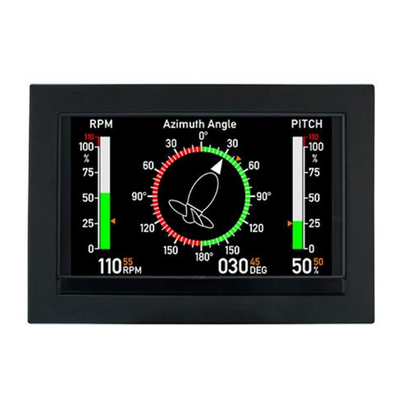
- Page 1 DESIGNER’S HANDBOOK fleXible Display indicator 4189350049C 4189350049C 1...
-
Page 2: Table Of Contents
Table of contents Useful reference documents ......................9 General information ........................10 Warnings, legal information, and safety ................... 10 2.1.1 Warnings and notes ......................10 2.1.2 Legal information and disclaimer ..................10 2.1.3 Safety issues ........................10 2.1.4 Electrostatic discharge awareness ..................11 2.1.5 Factory settings ........................ - Page 3 Change selected input via menu ....................21 Multi sources and automatic fall-back ..................21 3.5.1 Example – Fall-back function used in the standard heading indicator library....22 Menu structure ......................... 26 3.6.1 Installation Wizard ......................27 Surveyor info ..........................27 General menu structure ......................
- Page 4 4.7.5 Step 5 – Finish – XDi without NX2 module ................ 40 4.7.6 Step 5 – NMEA setup – XDi with NX2 module ..............40 4.7.7 NMEA auto scan and input selection ................. 41 4.7.8 NMEA auto setup example ....................41 4.7.9 Change NMEA setup ......................
- Page 5 5.7.4 Digital dimmer input ......................84 5.7.5 Relay outputs ........................85 NX1 and NX2 NMEA interface module ..................87 5.8.1 Connection of the NX modules ..................87 5.8.2 Connection and cable for NMEA ..................88 5.8.3 NMEA inputs ........................88 5.8.4 NMEA outputs ........................
- Page 6 11.7 CANopen TPDO/RPDO input adjust ..................138 11.7.1 PDO converter for azimuth/rudder ................138 11.7.2 CANopen Rudder transmitter (for example DEIF RTC 600) ......... 140 11.7.3 PDO converter for pitch %.................... 140 11.7.4 PDO converter for RPM ....................141 11.7.5 Universal PDO converters ....................
- Page 7 11.11.2 Relay mode ........................153 11.11.3 Relay event mode ......................153 11.11.4 Indicator-related relay setup..................158 11.11.5 Relay activation indication on a VI ................160 11.12 NMEA output using NX1 (or NX2) ..................160 11.12.1 NMEA output in standard virtual indicators ..............161 11.13 NX1/NX2 NMEA0183 setup menu ..................
- Page 8 12.7 Reservation .......................... 187 13 Appendix 2: Application examples ....................189 13.1 Application 1 - XDi azimuth system, CANopen and XDi-Net ..........189 13.1.1 Azimuth and RPM indicator system with set point ............189 13.1.2 Azimuth, Pitch and RPM system with set point ............191 13.2 Application 2 –...
-
Page 9: Useful Reference Documents
1 Useful reference documents Document name Document no. Link to web page XDi data sheet 4921250067 XDi-net/CANopen reference manua1 4189350066 XDi standard libraries 4189350067 Link to XDi XDi quick start guide 4189350046 Rudder systems Application notes 4189350085 XDi supported NMEA sentences 4189350086 Wind system application note with 4189350080... -
Page 10: General Information
DEIF A/S customers using the XDi, may copy and use the information from this manual in own manuals without additional permission from DEIF A/S. -
Page 11: Electrostatic Discharge Awareness
XDi product series and how you can best utilize it in your own system solutions. Either using a DEIF standard indicator library or have a custom library made to exactly match your needs for indicators and input profiles. -
Page 12: Product Introduction
DEIF offers a series of standard libraries with a selection of often-used indicator types and in addition, the opportunity to have customised libraries designed. -
Page 13: Virtual Indicator Library
Virtual indicator library All available virtual indicators in an XDi are located in the preinstalled XDi library. For each virtual indicator, there is also at least one VI-setup profile and one or more product profiles. Fig.1A Virtual indicator library structure for XDi- Dual or Multi It is important to be aware that all virtual indicators in an XDi library are predefined and version controlled to make sure that the requirements for relevant marine approvals are fulfilled. -
Page 14: Product Profile (Pp)
Fig.1B Virtual indicator library structure for XDi- Nav The library structure for XDi-Nav is basically the same as for Dual and Multi , but the product profiles (PP) contain the supported NMEA sentence setup and the default NMEA configuration. The virtual indicators (VI) can contain up to 4 predefined screens. -
Page 15: Vi-Setup Profile (Vs)
If the DEIF standard design does not fulfil your needs or wants, the XDi concept opens for a flexible pallet of customisation opportunities from small changes like adding a logo on a standard design, making a customised interface profile and all the way to a full-customised design fitting perfectly into your company’s overall product... -
Page 16: Upload A New Library
Other devices on the CAN bus may also use CAN data provided by the XDi. The DEIF XL, BW and BRW-2 indicators with CAN interface and TRI-2 CAN panorama indicator can be integrated in a system where XDi is providing calibrated CAN data. -
Page 17: Sourcing Data To The Xdi
Sourcing data to the XDi There are six different ways of sourcing measured data into an XDi for presentation on a virtual indicator, see the illustration below. In the VI-setup profile (VS), each virtual indicator input will be predefined to use a defined data type/instance in the Object index table, and this data type/instance will be pre-set to receive its input data using one of the input methods described below. -
Page 18: Xdi-Net As Data Input (2)
Example: The DEIF RTC 600 CAN angle transmitter with the default NodeID=1 is used as angle transmitter for an XDi azimuth indicator. The azimuth angle between +/-180deg. is transmitted as a signed 16 bit value located in TPDO 1, byte 0 and 1 (TPDO1 for NodeID=1 has COB-ID: 0x180+”RTC600 NodeID”). -
Page 19: Dam-Mpdo As Data Input (3)
3.3.2.1 XDi-net restrictions When “XDi-net variable data” is activated, all RPDO1s (COB-ID 0x200 to 0x27F) are allocated for XDi-net use and must not be used by other applications on the CAN bus. IF “Send XDi-net setup synch data” is active NodeID 127 is reserved and used as parking place for an XDi service unit and then COB-ID: 0x27F, 0x37F, 0x47F and 0x57F (=RPDO1-4) and 0x1FF, 0x2FF, 0x3FF and 0x4FF (TPDO1-4) are all reserved for this function. -
Page 20: Digital Data Input (5)
Propeller RPM instance 1 is located in Object index/sub-index: 0x3081-0x02 and always defined as absolute value with a resolution of 0.1 RPM, giving a max. of +/-3276.5 RPM. AX1 has two analogue input ports that can be configured for either current in the range +/-20 mA or voltage in the range +/-30 V. -
Page 21: Nmea Serial Data Output (7A And 7B)
It is also in DEIF standard navigation libraries that this function at present is used, but it can also be useful in different types of customized solution where a need for selectable data sources or a fall-back to a backup source is needed. -
Page 22: Example - Fall-Back Function Used In The Standard Heading Indicator Library
Source shift via CANopen. In manual mode it is also possible to control the active source by a CANopen parameter. Contact DEIF to get the details if you have a need for that. The parameter to used depends on the selected VI and VS profile in a given library. - Page 23 VI002 is only presenting heading. In the input adjust menu the name of the active data type is presented (GYRO 1). Press OK to open the multi-source menu: DESIGNER’S HANDBOOK 4189350049C EN Page 23 of 206...
- Page 24 The fall-back mode can be “Auto” or “Manual”. In manual mode the fall-back source number (shown in the next line) will be locked as the input source. Fall-back timeout: This parameter defines the time to go before the active source is replaced by the next priority source, after the active source has lost its data.
- Page 25 3.5.1.1 Heading indicator VI003 with rate of turn In the standard heading indicator VI003 the ROT has 2 fall-back sources, the input selected should be consistent with the selected gyro. It can also be set to fixed source or the same NMEA source can be selected for both ROT 1 and ROT 2. (The auto NMEA setup will normally select same source for both).
-
Page 26: Menu Structure
Menu structure The XDi wizard and menu system are operated by 4 push-buttons placed beneath the display. The buttons are used to set up the product during installation. After the XDi-D or -M is set up, the buttons are normally hidden away behind the front frame, and they are not used during daily operation. -
Page 27: Installation Wizard
3.6.1 Installation Wizard XDi has an installation wizard which starts automatically start at power up until the XDi unit has been set up. After first time setup, the normal menu structure is available offering “Surveyor info display”, “Master reset” and access to the user and installation menus. -
Page 28: General Menu Structure
General menu structure 1. The wizard and main menu pages are divided into 2 sections: the right side where you will find the menu with one menu line highlighted in the blue arrow 2. the left side pane shows detailed information about the highlighted menu Timeout: All menus except the start-up wizard have a timeout function. - Page 29 Select and press OK to open the line for editing. View and change setup parameters. Select from a list. Virtual keyboard for entering a new text line DESIGNER’S HANDBOOK 4189350049C EN Page 29 of 206...
- Page 30 Change a data value The detailed menu functions are in the relevant chapters. To learn more about XDi functions and menu system please see the chapter 6 XDi menu system and functions. DESIGNER’S HANDBOOK 4189350049C EN Page 30 of 206...
-
Page 31: Installation
4 Installation Unpacking The XDi indicator is delivered in a cardboard box. To protect the indicator, it is important to store it in the box until it is being mounted in the panel. This will also eliminate the risk of dust, or even worse, metal parts, to enter the cabinet through the airgaps in the rear part of the XDi that may sooner or later damage the unit. -
Page 32: Waterproof Mounting
4.2.2 Waterproof mounting DEIF support. The XDi front, front glass and buttons are waterproof. Therefore, the protection around mounting screws and between the XDi front flange and the surface of the panel where the XDi is mounted are the critical areas to obtain the required IP protection. -
Page 33: Installing A Can Bus System
The XDi base unit is equipped with two CAN bus ports, and CANopen is the standard interface protocol. The unique DEIF XDi-net Plug & Play extension to the CANopen protocol is used in all DEIF standard libraries for easy data sharing and is also used in many custom specific libraries, to make system setup and integration easy. -
Page 34: Can Bus Cable Recommendation
Only two termination resistors can be connected in a CAN bus network. Adding more terminations will overload the CAN drivers, disturb communication and in the long run maybe damage the CAN driver circuit. 4.4.3.2 Termination example This example shows a system where it can be considered where to insert the termination. If the total cable from the CAN angle transmitter to XDi 1 exceeds the max allowed drop cable length (10 m @ 125 kbps), then a 120 Ω... -
Page 35: Shielding And Grounding Of The Can Bus Cables
CAN bus Theoretical Recommended max Max. drop cable Max. bit rate max CAN cable length CAN cable length length accumulated (optimal installation) (practical installation) drop cable length 250 kbps 250 m 150 m 30 m 125 kbps 500 m 300 m 10 m 60 m 50 kbps... -
Page 36: Xdi Power Supply And Can Connections
XDi power supply and CAN connections Cable relief strip Connector 2 Termination Connector 1 XDi base unit connectors Type Terminal Signal Marking Remark CAN 1 CAN 1 GND Common, should not be connected *) connection CAN 1 LOW Connector 1 CAN 1 HIGH Supply +24 V DC... -
Page 37: Supply Voltage Monitoring
If the CAN bus cable is daisy-chained, the shield of the cable must be electrically connected beneath the strain relief strip and must not be connected to CAN common! Be aware, that the shield must not touch any other electrical parts or any metal parts around it. It is therefore recommended to connect the two cable shields up against each other and cover the shield joint with a heat shrink hose, before it is fixated below the cable strip. -
Page 38: Warning/Alert Output
180 and install the XDi indicator upside down. When the recommended DEIF colours are used in the virtual indicator design, the colours are very slightly affected by the change in viewing angle. For convenience, it is even possible to have this 180... -
Page 39: Step 2 - Select Product Profile
(In this example, there is only one PP). 4.7.3 Step 3 - Select virtual indicator The XDi is delivered with either a standard DEIF library or a customer library installed. The XDi library can contain several predefined virtual indicators which can be selected from this menu. -
Page 40: Step 4 - Select Vi Setup Profile
4.7.4 Step 4 - Select VI setup profile The Virtual Indicator (VI) setup profile contains pre-set parameters for: input sources, scaling, headlines, labels, units, indicator behaviour and much more. Selecting a predefined profile makes complex setup simple, secure, and easy. The VI setup is related to the VI selected in the previous step, and there may be up to 50 VI setup profiles for each Virtual Indicator to select... -
Page 41: Nmea Auto Scan And Input Selection
sure that all relevant NMEA sensors and system devices are connected to the relevant NMEA inputs on NX2 and that they are powered up and transmitting data. Then press OK to select the NMEA setup menu. 4.7.7 NMEA auto scan and input selection The next step is to select the highlighted “Auto scan and input selection…”... - Page 42 The wind data is coming from a DEIF WSS 550 wind sensor connected to RX/RTX 2 (RS-485) on the NX2 mounted in slot 2 (in XDi, this input is presented as 2.2). To calculate the true wind data, speed and heading information is required. In this example speed and heading data is available on one NMEA output from the ship’s integrated navigation system.
- Page 43 4.7.8.1 Stop scan - manual select To see what is actually selected, highlight “Stop scan – manual select…” and press OK. You will then get this picture: RED dot means that no external sources are available, in this case for the dimmer data group. YELLOW dot means that sources are available for some data in the group, but it should be checked.
- Page 44 4.7.8.3 SPEED In this example speed data is needed to be able to calculate the true wind data. The speed group is green, so everything is good. If we open this group, we can see which port and sentence is used to provide data. In this case, “Speed through water (STW)”...
- Page 45 Relative wind speed and direction are received from the wind sensor connected to input port S2.2 and contained in the MWV sentence with talker WI. The selection is made automatically and needs no further attention. The “Wind speed T 1” and “Wind direction T1” (T= true) are marked in the menu as XDi-net. The reason for this marking is that the internal wind calculator is active and delivers calculated data as XDi-net data, for presentation on the indicator as well as transmitted on CAN bus using the XDi-net protocol.
-
Page 46: Change Nmea Setup
The magnetic heading of the ship, “Heading M1”, is not available on NMEA, but it is not needed in the actual configuration, since the selected virtual indicator does not calculate and present geographic wind direction relative to magnetic north. The true heading, “Heading T1” is received from the navigation system connected to input port S2.1, provided by talker HE and contained in sentence HDT. -
Page 47: Automated Xdi Setup Via Can
Automated XDi setup via CAN Instead of making a full manual first time setup, it is possible to use an automated setup via the CAN bus. To make an automated setup, the XDi must have a unique NodeID assigned, two devices on a CAN bus must never have the same NodeID. -
Page 48: Detailed Product Description
5 Detailed product description XDi CAN bus All XDi units are equipped with two galvanic separated CAN ports as standard. 5.1.1 Detailed XDi-net/CANopen description A detailed description of the CANopen and XDi-net implementation is available in: XDi-net/CANopen reference manual. It is recommended to consult this document if you intend to fully utilise the CAN bus. The following is a short introduction to get started using CAN. - Page 49 Azimuth angle transmitter 1 for example, RTC 300 or RTC 600 Azimuth angle transmitter 2 Reserved…. … Pitch angle transmitter 1 for example, DEIF RTC 300 Pitch angle transmitter 2 Reserved…. … Centre console FWD FWD azimuth, RPM, Pitch 1 “...
-
Page 50: Overall Can Bus Parameter Settings
Overall CAN bus parameter settings Editing the CAN bus parameters list below requires a very good knowledge of CANopen and the special manufacture specific CANopen functions built on top to obtain the XDi-net functions. It is therefore highly recommended to consult the “XDi-net/CANopen reference manual” before making any changes in the CAN setup parameters. -
Page 51: The Can Bus Mode
Standard XDi-net is using RPDO1 as mentioned above, but in a custom library, it is possible to move the XDi-net to one of the other RPDOs: RPDO2, RPDO3 or RPDO4. This should only be considered if there is an unsolvable conflict in the user system due to the restrictions on RPDO1. -
Page 52: Error Indication
Error indication When the XDi detects errors, it alerts attention by the built-in buzzer (can be disabled from the user menu or by default in custom libraries) and a pop-up message as well as a CANopen message (see XDi-net/CANopen reference manual for details). If the error is missing data for an indication, the pointer of that indication starts blinking. - Page 53 The following table lists the errors and how they are displayed (can also be used for troubleshooting): Display pop-up text Warning Duration Error causes type • Warning On while error Used CAN data is not received before Data lost! persists timeout •...
-
Page 54: Xl, Bw, Brw-2 And Tri-2 With Scan
To define such combined system configurations in a combined system requires a good understanding of XL sCAN and XDi, so it is recommended to require some assistance from DEIF when such systems are designed. Application notes may be available from DEIF to help you specify indicators for your combined system. -
Page 55: Ax1 Analogue Extension Module
If there are more analogue or digital inputs in a system than one XDi can handle, it is possible to make several XDi units with extension modules work together providing all data on CAN for the rest of the indicators to use. This is made very easily when the XDi-net protocol is used, but can also be achieved using TPDO/RPDO data sharing. -
Page 56: Analogue Scaling
Input type can be changed from the XDi menu, the highlighted input type, in the example above, is used for a 4-20mA input, one of the most used analogue interface types for indicators. Input type Input parameter AX1 Input to be Marking Input Note... -
Page 57: Analogue Multi-Point Linearisation
The highlighted “Multi point linearization“ above is grey and cannot be changed from the menu. This is intentionally blocked to avoid unintentional changes that may result in a critical setup error. 5.6.4 Analogue multi-point linearisation When the analogue input is used for a data type where the output value is type “+/-X“, for example rudder angle, then at least 3-point calibration is normally used. - Page 58 The function is the same as explained for 3 point calibration above. The DEIF RTA 602 analogue rudder sensors (4-20 mA) do not need more than 3 linearisation points to fulfil the accuracy requirements in the ISO standard. That is why DEIF standard libraries do not support more than 3 linearisation points;...
-
Page 59: Ax1 Input Circuit - Principle Diagram
5.6.5 AX1 input circuit - principle diagram All inputs/outputs on the same AX 1 module are galvanic separated from the XDi’s supply voltage inputs, from both CAN ports and from input/outputs on other extension modules (XDi 144 and XDi 192 only). The 2 current inputs (including the low voltage inputs) are differential inputs, but not galvanic separated, so common mode rejection must be taken into consideration. -
Page 60: Common Mode Rejection
I/Os on the same AX1 module are not galvanic separated, and therefore common mode must be carefully considered when more than one input is used. 5.6.7 Common mode rejection The common mode potential between inputs and from one input to the analogue common/ground terminal (AGND) must not exceed: AX1 Inputs: High current... - Page 61 5.6.7.1 Example: rudder angle indicator system correctly configured (current source) The RAI system is with a DEIF RTA 602 rudder angle transmitter 4 to 20 mA, and with an external dimmer, all is supplied from the same 24 V DC source. When connecting the RTA to +24 V DC and the XDi 4 to 20 mA current input HI1- to AGND (common), the common mode voltage from HI1+ to AGND will in the worst case be approximately 1.2 V and is well within the +/-15 V common mode limit.
- Page 62 Vref instead, and it is separated from the current loop, then the system will work fine. This solution will be possible using the DEIF standard rudder library where dimmer and measuring circuit is configured to be connected to the same AX1 module and it will work for all XDi sizes (96, 144 and 192).
- Page 63 But please note that this solution will not be possible for XDi 96 (only one extension slot) and that the DEIF standard rudder library for XDi 144 and XDi 192 does not support this configuration either, so a customized library will be needed.
-
Page 64: Connecting To The Ax1 Module
5.6.8 Connecting to the AX1 module Analogue Extension Module AX1 Terminal Marking Remark AGND Analogue common connection (or ground) DIM/HV3+ Dimmer input configurable in the range, max. 30 V DC, port 3 It can be configured as an extra high voltage indicator input (max. +/-30 V DC), if it is not used for dimmer. -
Page 65: Configuration Of The Ax1 Module
5.6.9 Configuration of the AX1 module Analogue input ports used as indicator input are pre-configured in the “VI-setup” profile (VS) defined for a virtual indicator (VI); this is also the case if DIM/HV3 is used as indicator input. The configuration of the analogue dimmer input is pre-configured in the selected Product Profile (PP). If you by accident select a PP and a VS profile that are both set up to configure the DIM/HV3 input port, then the XDi will assign port 3 as dimmer input as defined by the product profile (PP) and the virtual indicator (VI) will miss the input configuration and indicate that analogue input... - Page 66 Example: In the DEIF standard library for azimuth thruster indication, it is possible to select a VS for sin/cos potentiometer input. This input pair has a predefined potentiometer supply voltage of +/-10 V, but this indicator will also work fine with any potentiometer supply between +/- 6 V and +/-15 V.
- Page 67 5.6.9.2 Sin/cos dual input with +24V as potentiometer supply The SIN/COS potentiometer is supplied form 0 to +24V and the used type of potentiometer will create an artificial 0V point on AGND. From the AX1 input it looks like the potentiometer is supplied by a +/-12V source. This setup will work fine even if the 24V supply is also used as voltage supply for XDi, simply because the AX1 input circuit is galvanic separated from XDi voltage supply.
- Page 68 XDi installation menu. Instead, you must select a VS profile where double triangle input is supported for the azimuth angle. (If there is no such VS profile for the virtual indicator you are using, please contact DEIF support or sales, they can help you find the best solution) In the following example the double potentiometer is connected to a stable external 0-10V power supply.
- Page 69 In this example the potentiometer is supplied by a single +10V DC voltage and the output swing is therefore 0 to 10V. This means that an artificial zero must be inserted as an analogue input centre value. This is to make the input swing symmetric around this centre point.
- Page 70 Like in the example with the sin/cos potentiometer it is possible to overwrite the internal Vref by and external supply, for example 24V, connect 0 V to terminal 1 AGND and +24V to terminal 3 (Vref). XDi will continuously measure the voltage on the Vref terminal and calibrate the measurements accordingly. It will even be able to eliminate slow fluctuations in the 24 V supply voltage, for example during an emergency situation where the indicator system is powered by a 24 V battery source with a slowly dropping voltage.
- Page 71 5.6.9.7 Single high voltage input AX1: +HV1 (High voltage 1) on terminal 11, +HV2 on terminal 7 or +HV3/Dim on terminal 2. All 3 with 0V reference at AGND, terminal 1. The high voltage input can be configured to use full data resolution within the ranges: +/-7.5 V, +/-15 V or +/-30 V, this secures a very high accuracy in the analogue measurements.
- Page 72 This can always be adjusted if needed in the installation menu / input adjust. Note: If you change a 4 – 20 mA input to a voltage input you will of cause need to change the input scaling but also remember to change or deactivate the input error limits.
- Page 73 The high-voltage input can be pre-configured as a “V potentiometer input” type; this means that the input data is measured relative to the actual measured reference voltage. This means that any drift or fluctuations in the reference voltage will be corrected. If there is a need for using another reference voltage than the one provided by the AX1 module, it is still possible to use the correction function simply by overwriting the reference voltage by an external reference voltage.
- Page 74 In a single potentiometer application, for example when a potentiometer is used for rudder angle measurement. It is possible to detect if a connection to the potentiometer is lost, it just requires that 0V is not part of the valid measuring range.
- Page 75 In all DEIF standard libraries you will find product profiles for analogue dimmer connection to the dimmer input on AX1 located in slot 1. It is important that the AX1 module is located in the correct slot specified in the PP documentation / help-text.
- Page 76 and like previously described for the HV input, it is possible to overwrite the reference voltage by an external voltage (7.5-30 V) and still get fluctuations corrected. It is recommended to use a potentiometer in the range from 1 to 20 kΩ. 5.6.9.15 Dimmer input using PWM The XDi does not directly support PWM (Pulse Width Modulation) input for dimmer control, but it is possible to...
- Page 77 10 seconds (100 samples of 100 ms). Dimmer error handling In DEIF standard libraries, the default dimmer settings and behaviour are predefined in the available selection of Product Profiles (PPs). Select a PP that best match the dimmer needs and make necessary parameter adjustments to match the installation using the XDi user menu.
-
Page 78: Share Analogue Data Via Can
0 and 1 (I16). Note: The sCAN integration is available for DEIF XL, BW, BRW-2 and TRI-2 CAN indicators. In the XDi data structure most data is of type I16, but there are a few XDi-N data types as mentioned that contains more than 16 bits of data (for example Position and UTC time and date). -
Page 79: Dx1 Digital Extension Module
DX1 digital extension module The digital extension module has two galvanic separated digital inputs and two general-purpose relay outputs. The digital inputs are primarily intended for use as direct RPM pickup input(s), but may be configured differently. 5.7.1 DX1 input circuit - principle diagram The two digital inputs are identical, and the principle diagram below illustrates the main function. -
Page 80: Digital Inputs Configuration
5.7.3 Digital inputs configuration The inputs can be configured as: • Two independent inputs for single direction RPM measurements. • Input pair for bidirectional RPM measurement. • Input pair for dimmer control (up/down and colour shift on simultaneous activation) • Input pair for control purposes* (modes: 4 stage input or set/reset) •... - Page 81 5.7.3.2 Recommended sensor types For the practical test of the DX1 RPM function, we have used two different inductive sensors from BALLUFF sensor. • NPN type: BES 516-329-BO-C-02 BES01EF, normally open, 2 mm sensing distance • PNP type: BES 516-325-BO-C-02 BES01AZ, normally open, 2 mm sensing distance The full specification of the tested sensors can be found www.balluff.com and can be a useful reference for...
- Page 82 5.7.3.4 RPM pickup cable recommendation The galvanic separated inputs are well protected and not very sensitive to electrical noise. It is, however, recommended to use a shielded twisted pair cable in installations where long cables are used or where strong electromagnetic disturbance may occur.
- Page 83 When the disc is rotating clockwise, the 25 % mechanical offset between the sensors will delay the signal from sensor no. 2 with 25 % of the period time (90 degree phase shift) as illustrated below. When the disc rotates Counterclockwise, the 25 % mechanical offset between the sensors will make the signal from sensor no.
-
Page 84: Digital Dimmer Input
The input offset between sensor 1 (input 1) and sensor 2 (input 2) must be between 5 % (min) and 45 % (max) of the period time, for the XDi to be able to determine the rotation direction. In the example above, input 1 is ahead of input 2 and therefore the RPM direction is positive. -
Page 85: Relay Outputs
The digital dimmer uses both inputs as an input pair, making it possible to change the dimmer level up or down by activating the input by a connected push-button contact. The function has 2 modes: A. Dimmer up/down, input 1 up and input 2 down. B. - Page 86 A relay output can be: a) Predefined in the product profile (PP) as product warning or alert outputs. b) Predefined in the VI-setup (VS) as an output from a virtual indicator for example set up to be triggered when the pointer enters a restricted section of the scale. c) Predefined in the VS to be activated by a control flag.
-
Page 87: Nx1 And Nx2 Nmea Interface Module
NX1 and NX2 NMEA interface module Serial NMEA data is often the primary data source for XDi-N. To receive and transmit NMEA data the NX2 module must be mounted on the rear plate of the XDi-N main unit. To reduce the number of extension modules needed, NMEA data can be shared with other XDi-N units via the CAN bus using the XDi-net protocol. -
Page 88: Connection And Cable For Nmea
The NMEA inputs RX1 and RX3 is galvanic separated and fully complies with the two IEC 61162 standards. The RX/TX2 (RS-485 port) is used to connect a DEIF wind sensor to an XDi-N wind indicator. This port can also be configured as either an input or an output, in both cases it will use the NMEA data protocol. - Page 89 The contact input setup is found in the installation menu: A potential free pushbutton connected between contact input C-IN1 (term. 5) and Common (term. 9), on the NX module in Slot 1, will now work in parallel with button 1 on the front frame and toggle between the screen modes. If a pushbutton is connected between C-IN2 (term.
-
Page 90: Xdi Menu System And Functions
6 XDi menu system and functions Overview of the overall menu structure in XDi 7 XDi menu level 1 – short push A short push on one of the 4 pushbuttons on the front will first role up a soft key menu line and it will not make any changes to the settings only show the help text line. -
Page 91: Menu Level 1 Functions Only In Xdi-N
8 Menu level 1 functions only in XDi-N In this description the DEIF standard wind indicator VI007 is used as example. Toggle between screens (button 1) The XDi-N can have up to 4 screen in a virtual indicator and some of the standard wind indicators have 2, 3 or 4 screens presenting different wind data types or combinations. -
Page 92: Quick Menu (Only Xdi-N)
Quick menu (only XDi-N) The quick menu opens for the basic user setup functions: • Unit profile toggle, • Unit profile setup • VI mode group setup • Data and time setup • User menu (gives access to dimmer, warning and sound setup) 8.3.1 Change unit profile The XDi-N supports different selectable data units. -
Page 93: Change Unit Profile Setup
To toggle to Profile 2, push the “OK” button shortly and push the left button to go back to normal operation. The toggle function on the “OK” front button (button 4) makes it possibel to to change unit using only two buttons - button 4 and button 1. -
Page 94: Change Unit Profile In A Can Bus System
In this quick menu it is possible to reorganize the different screens in a virtual indicator (VI) with multiple screens. We will use one of the DEIF standard wind indicators (VI007) with 4 screens as example. By default, Screen 1 is assigned to Mode 1, Screen 2 to Mode 2 and so on as it can also be seen below in the quick menu picture: DESIGNER’S HANDBOOK 4189350049C EN... - Page 95 If you want to change the order in which the screens are toggled when you push the left front button, you can do it in the Mode Group setup menu: If you want this XDi to toggle between screen 4, 2, 3 and 1 then you can change the assigned screens for each mode.
- Page 96 Now the toggle sequence for this indicator is changed. Toggle with front button 1 If you for example in the virtual wind indicator above only want to use Screen 1 and 4, then just set the mode 1 to 4 like this: Now XDi-N will toggle Sc.1, Sc.4, Sc.1, Sc.4 and so on.
- Page 97 Now press the several times to return to normal operation where you now can toggle between screen 1 and 3 without getting a data lost warning. Note: In this case it is only the true wind direction relative to ship that needs to be disabled. The True wind speed is always the same and independent of which reference is used for the true wind direction (the ships bow or the north pole).
- Page 98 8.3.4.2 Use of screen mode grouping in a CAN based system Like dimmer grouping it is also possible to group several XDi-N indicators with multiple screens in a screen mode group. All indicators in the same group will show the screen that is assigned to the active mode for the group. If the screen mode on one of the indicator in the group is toggled to a new active mode, then all the other XDi-N indicators in this group will receive a CAN command to follow.
- Page 99 The following picture illustrates this function in an actual system where the mode function is used in the 4 XDi-N indicators out of the 5 indicators in an overhead panel: XDi1 (Navigation) XDi 2 (Navigation) XDi 3 (Navigation) XDi 4 (Navigation) XDi 5 (Dual) VI number VI001 - Weather...
-
Page 100: Date/Time Setup
It is possible to use the external contact input C-IN 1 on a NX2 (or NX1) NMEA extension module to toggle the mode. You must in that case make sure that contact input 1 and 2 (C-IN1 and C-IN2) is setup to control button 1 and 4. - Page 101 NMEA is normally the default source setup for date and time: This source setting is correct for the XDi-N where the NMEA time data is connected and selected in the initial NMEA setup procedure. Note: You can always go into NMEA input setup and see the actual NMEA data and time setup. 8.3.5.2 Local time offset shared via NMEA If other XDi-N units needs the local offset via CAN bus, then “Send on CAN”...
- Page 102 8.3.5.3 Local time offset received via XDi-net XDi indicators that needs local time offset via XDi-net (CAN) must be setup so that “Source input” is changed to XDi-net: Change the source input to XDi-net: The local time offset parameters that XDi-needs, is now received via XDi-net and it is not possible to change any of the other parameters since it is not relevant (they are greyed out in the menu).
-
Page 103: Quick Access To The User Menu
In this example the offset is 3:00h. The manually inserted local time offset can also be shared via CAN with other XDi unit’s setup to manual time offset and one of the indicators (kind of master) is setup to share on CAN like above, manual data is sent in sub index 0x07). -
Page 104: Menu Level 2 - Long Double Push (Easy Access)
9 Menu level 2 – Long double push (easy access) The three main menus are accessed by pressing a combination of two push-buttons simultaneously for approximately 5 seconds. When the display writes “Loading”, your selection has been accepted. The table below shows the valid push-button combination to use to access a menu from normal operation mode. Menu/Function Button 1 Button 2... -
Page 105: Surveyor Information (Info)
Surveyor information (INFO) Press button 1 and 2 for more than 5 seconds, and the surveyor page will provide information about the XDi and its configuration. Serial number and software information CAN bus settings Information about extension modules (if mounted) Library owner and library number Active virtual indicator number Thumbnail picture of the active virtual indicator... - Page 106 There are 3 levels of master reset: 1. Reset: will bring all system and indicator related parameters back to factory settings, but it will not change display colour calibration made in connection with a previous setup. The setup wizard will be started after a reboot sequence.
-
Page 107: User Menu
10 User menu The user menu gives access to change the predefined basic setup parameters, where advanced installation settings are located in the special installation menu. The user menu is used for adjusting: • Dimmer (Fixed dimmer level, Dimmer group, Dimmer setup, Day/Night colour) •... -
Page 108: Fixed Dimmer Level
In normal dimmer mode (without auto colour shift), the dimmer level from 0 to 100 % controls the backlight level range from “Min backlight level”. This must be set at the lowest backlight level where the display is still readable in dark night conditions (typically level 10) to “Max backlight level”, which is the level used in full daylight. -
Page 109: Dimmer Groups
2 and 3. In all DEIF standard libraries and many customized libraries you will find a special ECR product profile. It is highly recommended to use that profile in applications where the backlight always is turned ON, you can easily adjust the level using the pushbuttons or in platform 1 libraries (version 0001 or higher) use this fixed dimmer menu to fine tune the level. - Page 110 A popular system dimmer method is to connect an analogue dimmer control output (for example a potentiometer) to one XDi in the group (3) and then set up the rest in the group to use dimming via XDi-net (1). This is a simple plug and play method.
-
Page 111: Dimmer Setup
10.1.3.2 Local mode In “Local” mode, the XDi will respond to a dimmer command sent to the local dimmer group index or get the analogue or digital dimmer input from an extension module mounted on this XDi unit. In local mode, the XDi will not share analogue or digital dimmer data via XDi-net. - Page 112 Min backlight level (local) is the backlight level that equals a dimmer value of 0 %. This setting should never be set to 0 since it turns the backlight totally off, and it will no longer be in accordance with regulations for a display- based bridge product.
- Page 113 10.1.4.2 Analogue or digital dimmer input When the XDi-net function is enabled the analogue or digital dimmer level used by an XDi unit will normally also be shared via XDi-net with all XDi units being part of the same dimmer group and of course connected to the same CAN bus.
- Page 114 Dimmer function: defines the function of the two digital inputs used for dimmer. Selections are UP/Down or UP/Down/Colour. The functions are described in the DX1 section. Detection: defines how the signal on the digital input must be detected, either trigger the function on a “Low to High”...
- Page 115 Use V output as: This setting can be used when a dimmer potentiometer is connected using the V output as supply (typically 7.3 V). The reference voltage V is internally monitored. When “Dim.max” is selected, the measured reference voltage will automatically be used as the maximal dimmer voltage, and the dimmer input voltage will be measured relative to this reference.
- Page 116 The dimmer error level: this is the dimmer level used if the dimmer voltage drops more than 2% outside the defined dimmer low level. When this level is set to 50 %, the backlight will shift to 50 % in a fault situation, Raw data filter: is an averaging filter that can be adjusted to reduce noise and fast fluctuations on the input voltage.
- Page 117 10.1.4.6 Dimmer PDO converter setup This requires that a PDO converter is defined in the Product Profile (PP) as input source for each dimmer group that must be supported by the selected PP. In most cases, a TPDO data value is defined for each of the 9 dimmer groups.
-
Page 118: Day/Night Colour Shift
10.2 Day/Night Colour shift In the XDi library, each indicator will normally be defined with at least day and night colour designs, but it is even possible to add a design for dusk conditions if needed. The intension of the colour shift in combination with the backlight dimming is to optimise visibility and contrast in any ambient light condition on a ship’s bridge. - Page 119 10.2.1.1 Colour shift source in mode 1 In mode 1, the source used to make the colour selection can be: NONE-fixed colour! Select this setting if a fixed design is needed (Day, Dusk or Night). Digital I/O option Parameter is received from digital input, when the digital input dimmer mode supporting colour shift is selected.
- Page 120 The following menu is available: The PDO may be received via CAN1, CAN2 or both The COB-ID of the PDO used for data transfer may be changed. Also, the mapping of the 2 input bits in the 64 bit data frame of the TPDO may be changed via menu.
-
Page 121: Auto Day/Night Shift Mode
10.2.2 Auto Day/Night shift mode “Auto Day/Night shift” and “Auto Day/Dusk/Night shift” modes are basically the same mode. The only difference is that Day/Night mode does not have a dusk indicator design implemented in the library. If Day/Dusk/Night is selected in a library without dusk design, the night design will be used instead of the dusk design. - Page 122 10.2.2.2 Auto Day/Dusk/Night Colour shift This function works similar to auto Day/night shift, but has an extra step for dusk. 10.2.2.3 Auto shift setup menu If auto colour shift is activated, the menu below will be available for fine-tuning the parameters. For example, adjust the backlight levels to best match the actual location of the indicator.
-
Page 123: Warning And Sound
When shifted to night colour, the backlight level will automatically be increased to 250 and dimmed down to min. when dimmer level reaches 0 %. Only the day min. backlight level and the night max. backlight level is used in this example, but if a dusk design is available in the installed XDi library, then the dusk min. -
Page 124: Warning Setup
10.3.2 Warning setup The menu below makes it possible to adapt the need of warnings to the actual application. CAN bus error warning indicates a problem on the CAN bus and should be set OFF if CAN bus communication is not used. Supply voltage monitor is mostly used in systems where redundant power supply is used. -
Page 125: Warning Marks
In indicators where warning marks are implemented in the virtual indicator for example warning marks on a tank level indicator. The following example is from DEIF standard library for XDi 96 D that is containing tank level indicators. Normal level... -
Page 126: Sound Setup
10.3.4 Sound setup The XDi has a built-in speaker that can provide different sound signals. In this menu, it is possible to activate or deactivate beep on key-press. The beep response makes it much easier to operate the menu system during installation and setup. You should keep this function ON. -
Page 127: Accessing The Installation Menu
IMPORTANT: The installation menu must only be accessed by trained or skilled personnel who know the XDi system and the detailed operation of the XDi device. If CAN bus is used, it is also recommended to consult the “XDi-net/CANopen reference manual”. Warning: Changing mode or parameters may jeopardise the operation of the XDi. -
Page 128: Edit Virtual Indicator
Please note, that it is not possible to skip the wizard directly using a soft-key (push-button) if it is started by accident. You can remove the power when the wizard is in start screen, and the XDi will start up in normal operation mode again when repowered. - Page 129 Each VI in a library can have several headlines, labels, or units. The first headline is Headline 0, Next Headline 1 and so on. In the following we will use headline as an example. In each VS profile for a VS the will be a list of up to 32 predefined headline texts to easily select from during installation setup.
- Page 130 To select or add a new headline, press OK. A headline is predefined in the virtual indicator design and each VI in a library can have several headlines, the first is Headline 0, Next Headline 1 and so on. Select a new headline from the list and press OK. Each headline in a VI has a list of up to 32 predefined headline texts to choose from.
-
Page 131: Warning Marks/Restricted Band
11.3.1.3 Select new label or unit If one or more text boxes with labels or units are embedded in the selected virtual indicator, it is also possible to select a new label or unit from a list or to add a new text from the virtual keyboard. The procedure is exactly the same as explained for headlines. - Page 132 Select warning marks for Prop RPM 1, press OK. The critical band is inactive since the high and low value is both 32767 (largest positive value = not available). A critical band is disabled when high and low is the same value. To activate the band, you must insert the critical band boundary values.
-
Page 133: Indicators
DX1 relay output is included in the selected VS profile. This is for example used to activate the wind speed alarms in some of the wind indicators available in the DEIF standard wind indicator library. - Page 134 The visibility function has 5 modes: The pointer and/or digital readout is always visible. Auto: The pointer/readout is controlled by a flag defined in the VS. Off: The pointer/readout is always invisible and inactive (OFF). Inside: The pointer/readout is only visible when data is inside the set visibility band. Outside: The pointer/readout is only visible when data is outside the set visibility band.
-
Page 135: Adjust Input Settings
Adjust input settings The XDi 192 Multi-indicator with DEIF standard azimuth library shown below is used as an example. The virtual indicator below is a multi-type with 6 data inputs: azimuth angle, pitch % and RPM / %RPM. The set point (commanded) values are also presented by orange triangle pointers and orange digital readouts. -
Page 136: Xdi-Net - Input Adjust And Special Use
In some cases, NMEA0183 input is available as input source (requires NX2 NMEA i/o module). NMEA is however a little special and requires its own dedicated setup menu. In the adjust input menu, that we are looking at now, data sourced from an NMEA input will be presented in the same way as XDi-net data. -
Page 137: Canopen Mpdo As Data Source
Rudder angle % Rudder Pitch angle % Pitch TPDO converter % RPM % Trust % Power Rudder angle % Rudder Pitch angle % Pitch DX1 digital input % RPM % Trust % Power There can be other data types where the input device is set up to generate both an actual value and scale this value to a % value in addition. -
Page 138: Canopen Tpdo/Rpdo Input Adjust
The azimuth angle in the virtual indicator used in this example is predefined in the VS profile to come from an angle transmitter (encoders) with CANopen interface (for example DEIF RTC 300 or RTC 600). The transmitter sends the measured angle between +/-180 represented by a signed 16 bit relative data value packed into a TPDO in byte 0 and 1. - Page 139 Often you will however make the zero angle calibration of the CAN azimuth or rudder transmitter (encoder) instead; it is always good praxis to adjust or calibrate the data source if possible. To zero-adjust DEIF RTC 300 or RTC 600 angle transmitters, please see the quick start guide or the detailed installation instructions.
-
Page 140: Canopen Rudder Transmitter (For Example Deif Rtc 600)
If there are more than one CAN based angle encoder on the same CAN bus, the TPDO COB-ID can easily be changed via the menu above. If for example a DEIF RTC 600 CAN angle transmitter is programmed by wire to use... -
Page 141: Pdo Converter For Rpm
RPM as well as most data types in the internal object index table are defined with 0.1 resolution (see the XDi- net/CANopen reference manual for details). The following example is taken from “DEIF standard azimuth library” where the virtual indicator VI003 is selected, and the setup profile VS02 for CANopen TPDO is selected. - Page 142 In this example, the default scaling setting in the VS02 profile is changed, so that +/-200 RPM is equal to 100 % (110 % is 220 RPM). Default setup. Default VS02 settings: In the VS02 profile, the actual RPM values are set up to be scaled 1:1 (still with resolution 0.1, meaning that the RPM value in the menu is presented as RPMx10).
-
Page 143: Universal Pdo Converters
CAN data field length: this must match the CAN data resolution of the used angle transmitter. The XDi supports any resolution from 10 to 16 bits. (DEIF RTC type angle transmitters use full 16 bit resolution for optimal accuracy) Mapped data. LSB located at bit no.: defines where the 10 to 16 bits of data are located in the 8 byte data frame of a TPDO or RPDO. -
Page 144: Ax1 Analogue Input Adjust
the incoming azimuth angle, the change made will in the first place only affect the XDi where the adjustment is made, even though several XDi units on the network need the same adjustment. To avoid the need of making the same adjustment individually on all the XDi units in a system using the same encoder, XDi has a built-in synchronisation function. - Page 145 Direction is quite useful if the analogue input is reversed in the actual installation. But be careful using it on 4-20mA input since it is the +/- sign on the input that is changed when direction is changed ! Input type: can be changed (see below). Input error value min and max: by setting a valid input range between min and max, it is possible to get an AX1 input...
- Page 146 The input types are described in more details below and in the chapter regarding AX1 module. 11.8.1.2 Analogue input with multi-point linearisation The azimuth angle input is only using 2 point linearisation (scaling) as shown below. Input point 1: when input type is +/-20 mA, this parameter is the input current in µA that must be equal to the Output point 1: in this case, the angle -1799 at the standard resolution of x0.1°.
-
Page 147: Ax 1 Analogue Input For Rpm Set Point
The scaled data provided by the analogue interface we have looked at may be shared on CANopen using the XDi- net protocol. In all DEIF standard libraries this function is by default set to CAN1 & CAN2, so data is automatically shared with another XDi “repeater”... - Page 148 Name: identifies the input parameter, and it may be changed. Source: analogue input (single). This is fixed defined in the selected VS. Data value equal to +100 %: is used to calculate the %RPM set point value (and also %Thrust (%RPM) and %Power (%RPM) .
-
Page 149: Dx1 Digital Input Adjust
Potentiometer correction: if a potentiometer is used for the analogue set point, this feature may be useful (see previous chapter for details). Filter mode: in this case, the normal linear filter type is used. Filter size: can be set between 0 and 100. - Page 150 This input is also controlling the %RPM bar graph, where the default scaling is set up to 3000 RPM with a 0.1 RPM resolution. In the DEIF standard library, the default 3000.0 RPM is equal to a 110 % RPM scale value. This means that 100 % must be set up to 27273 (x 0.1 RPM = 2727.3 RPM).
-
Page 151: External Input For Control Flags
In some cases, it can be useful to be able to use a spare analogue input as a digital control input, but it will normally be in connection with a customized library solution. If you have special wishes, please contact the experts at DEIF to get help to find the best solution for your application. DESIGNER’S HANDBOOK 4189350049C EN... -
Page 152: Dx1 - Universal Digital Input Of A Control Flag
The control flag function setup and default settings must be predefined in the VS for the actual virtual indicator. The setup menu is the standard analogue input adjust menu, presented in another section of this document. More complex control of a flag may require digital input(s) on the DX1 module instead. 11.10.2 DX1 - Universal digital input of a control flag Control flags may also be externally controlled using a digital input (DX1). -
Page 153: Product-Related Events
11.11.1 Product-related events The “PP Relay active” function defines which product-related events the relay must be controlled by (control event). The following event selections are available: disabled, XDi warning, XDi caution or XDi warning & caution. It is the same warnings that the XDi presents in an amber (orange) pop-up on the display, and cautions are the ones presented periodically in a yellow pop-up. - Page 154 11.11.3.1 Normal mode The relay will act directly on the event. When the event occurs (true), the relay will be activated and stay activated as long as the event is true and first deactivate when the event disappears (false). Relay in ND mode 11.11.3.2 Timer mode This is a function that runs every time the event occurs, but only once, so the event has to disappear, before the...
- Page 155 Relay in ND mode. The timer mode can be used to make a short event activate a longer relay output. This can be useful in several situations where the relay is driving a warning lamp or an acoustic alarm. If the short event happens again after “Timer min.”, then the sequence will reappear.
- Page 156 In this example, the event lasts longer than “Timer Min.+Timer Max” time limit, and the relay output will switch OFF when the time limit is reached. In general, the timer function can be used to secure a minimum length of the relay output, but also to shorten a very long event.
- Page 157 Special acknowledge setup 1 In this mode you can set the Relay timers to “Disabled”, If you disable both “Relay timer MAX” and “Relay timer MIN” The relay will activate immediately when the rudder angle exceeds 30° and it will stay active until you make an acknowledge by pushing any of the front buttons.
-
Page 158: Indicator-Related Relay Setup
If the event continues after “Timer Min.” +” Timer Max.” time limit, then the timer will be reset and restarted when this time limit is reached. This activates a new output pulse of a length defined by “Timer Min.”. This function will periodically activate the relay output as long at the same event still exists. If the event is shortly interrupted, the toggle function will restart and act as if it was a new event. - Page 159 When the “VI relay active” is set up, the “Name” and the “Index, Sub-index” defines which data type or flag is controlling the relay output. Example: we want the relay 1 to be controlled by Propeller RPM instance 1, then the object index will be 0x3081 (Prop.
-
Page 160: Relay Activation Indication On A Vi
If you need a special warning or alarm function in your customized library, please take contact with the experts at DEIF. 11.12 NMEA output using NX1 (or NX2) Some data types, generated by the XDi via analogue or digital input, may be necessary for external systems, such as Voyage Data Recorder (VDR) or the integrated navigation system. -
Page 161: Nmea Output In Standard Virtual Indicators
11.12.1 NMEA output in standard virtual indicators In most cases DEIF standard indicators are prepared for NMEA output support it there are a spare slot for a NX extension module. If it is standard propulsion indicators showing RPM, like the type we looked at in the previous example, then the NX module with NMEA are supported and preconfigured in the relevant VS profiles. -
Page 162: Com Port Setup
RX3 use a separate UART and can be setup independent of the other 2 ports, this is COM 3. 11.13.1.1 Standard NMEA input/ output In DEIF standard libraries all the RS422 (and RS485) NMEA COM ports are by default set up according to IEC 61162-1/NMEA0183 standard: DESIGNER’S HANDBOOK 4189350049C EN... -
Page 163: Nmea Output Setup
It is possible to change the settings for each COM port independently. A XDi-N with two NX2 modules mounted will have 6 COM ports that can be configured independently. Changing bitrate can be used to increase the data bandwidth, default NMEA0183 is 4800 bps. 11.13.1.2 High speed NMEA input / output To comply with IEC 61162-2 you must change the Baud rate to 38.400 bps. - Page 164 To change the default settings of the supported NMEA sentences shown in the menu below, simply highlight the sentence line and press OK to open the setup menu. If no NX1 module is mounted on the XDi, the NMEA output setup menu line cannot be selected (greyed out). If you press OK on the highlighted menu above: It is only the data types that is relevant for the selected indicators that you can enter and activate.
-
Page 165: Nmea Input Setup (Nx2 Only)
If the NX1 module was mounted in Slot 1, then “Slot1 Port1” can be selected. The transmit interval can be changed in fixed steps from 50 ms to 1 s (or output can be Disabled). You must consider the very limited bandwidth of the NMEA0183 port running at 4800 bps. Update every 1 sec. is often used for data not changing that fast. - Page 166 When the user menu is open, press the “secret button combination” 2 and 3 for more than 5 seconds to open the installation menu. In the installation menu highlight “NMEA setup” and press OK Select NMEA input setup…. If a new NMEA source is added or a source is moved to another input port, you must run the auto scan again to update the list of available data sources.
- Page 167 NMEA input setup menu may help us). DEIF standard heading repeater, using the rotating “endless tape” indicator for excellent readability even on a long distance. This indicator also has a rate of turn indicator (ROT) in the top part.
- Page 168 In this case XDi has found sources for all 6 NMEA data types that is supported by the selected product profile and used by the heading indicator we have selected from the standard heading indicator library. As we will see later the number of usable sources does not necessarily need to be 6 it depends on the indicator we have selected, and the data needed for that indicator.
- Page 169 RED dot means that no external sources are available, in this case for the dimmer data group. YELLOW dot means that sources are available for some data in the group, but it should be checked. Some data types may need manual selection or some may be missing.
- Page 170 If only HDT was sent, one sentence from each of the two gyro compasses, then XDi would detect 2 usable sources for both Heading T1 and Heading T2 and ask you to make a manual selection. In this case we can see that Heading T2 is also using HE HTD, so what you need to do is highlight Heading T2 and press OK to open it for editing: In the list you can see all the sources that XDi has detected as potential sources for “True heading”.
-
Page 171: When Is Manual Nmea Input Selection Necessary
Possibilities in a customized library The DEIF standard heading library we have used as example is made for general purpose use and the room for auto-selection of NMEA sources are therefore relative wide. In customized libraries it is possible to limit the auto... - Page 172 Select “Manual input configuration…” You will see a list of the NMEA data groups that this XDi is able to support. Note: The dimmer is red because there is no NMEA data available for dimming in this system. The Wind group is yellow because not all data in the group has a source assigned, in the below picture we can see that it is the Geographic wind direction relative to the magnetic north pole that is not available.
-
Page 173: Changing Filter Settings
Select the “Offset:” line and insert the angle correction. Be aware that XDi is using 0.1 resolution of the angle values, so a positive angle correction of +10.0 degrees must be entered as 100. The offset is added to the received wind angle. If the received wind angle is +70 degrees (700), then the correction of 100 (=10.0 degree) is added and the wind indicator will show a relative wind direction of +80.0 degrees. -
Page 174: The Other Input Configuration Parameters
When the wind direction is received every second from the wind sensor, the filter value 8 means that data is averaged over the last 8 measurements or over 8 seconds. Please note that relative wind speed and wind direction both by default have a filter value. -
Page 175: Service Menu
11.16 Service menu The service menu consists of two pages, containing product information and setup status that may be quite important to have on hand in case DEIF is contacted in relation with service or support. 11.16.1 NMEA monitor XDi has a built-in monitor function that can present all NMEA sentences received (RX) from devices connected to one of the NMEA inputs on an NX2 module. - Page 176 The first monitor is monitoring the NMEA sentences sent on all COM ports both inputs and outputs. When two NX2 extension modules are mounted on the XDi, there can be up to 6 active ports, that can result in a lot of NMEA sentences to look at in the monitor.
- Page 177 In some case the same NMEA sentence can contain different data types, it can for example be MWV that is sent one time with relative wind data and shortly after again but now with true wind data. To see one or the other it can be useful to be able to freeze the screen.
- Page 178 In this example, the missing wind data is caused by the status flag V indicating that the wind sensor is not able to calculate the wind data. The data sent from the sensor is invalid. If there are no communication errors registered and no strange looking sentences without count and time, then it looks like the communication with the senor is fine, so the fault must be found in the sensor and not in the installation / wiring.
-
Page 179: Product Information Page
11.16.2 Product information page The product information page contains information of the product software and installed library: MED approved indicator Not MED approved indicator Please note, that the library version uniquely identifies the full software (Platform, Qt App. and C-App) and library installed in an XDi unit. -
Page 180: Product Configuration Page
11.17 Trouble shooting help If you contact DEIF to get help with solving some installation and configuration problems, then it is always a great help if you take a picture of the Product information and the Product configuration page and attach that to your request for support. -
Page 181: Appendix 1: Colour Calibration - Service Instruction
12 Appendix 1: Colour calibration - service instruction The menu function in this document is available in all XDi library packages released after the date 25.03.2020 - but only if the version number is v2000 or higher. Note: Library ver.2xxx means that the library package includes the needed XDi platform 2 software. Libraries with version v0xxx or v1xxx must first be moved to software platform 2 and released as a platform 2 library to get the new functions. -
Page 182: Colour And Backlight Adjustment
The nature of the backlight degradation makes it impossible to adjust an old unit to match the warm white screen colour on the new unit. Instead, the new unit must be adjusted to match the background colour of the old indicator, and maybe also reduce the backlight slightly to make a good match. -
Page 183: Display Calibration
12.3 Display calibration When the calibration menu is entered the adjustment display will look like below. Display calibration screen The selected parameter to be adjusted is marked with the black cursor frame. 12.3.1 Menu functions The calibration menu has 2 main functions: 1) Adjust the red, green and blue colours 2) Adjust the max backlight level at 100% Dimmer setting (max level is 250) 12.3.2... -
Page 184: Some Experience
When you now want the white screen to be more bluish, you push the ˄ front button to increase the blue colour. Since blue colour is already at max 252 the red and green colours are both reduced one step for each push on the ˅... -
Page 185: What Happens If You Install A New Library Package
Accept: to save your new adjustment Reset: to go back to original factory settings, this can be very useful if you have lost the overview of your changes. After resetting you can go back and make a new attempt to match the colours and backlight level. 12.4.2 What happens if you install a new library package If you have calibrated the display and accepted to saved calibration values, they will be present even after... -
Page 186: Display Calibration Step By Step (Example)
12.6 Display calibration step by step (Example) On a vessel equipped with double rudder, we have replaced a faulty XDi192D in their engine control room with a brand new service unit. After normal setup both indicators are again running as they should, but the high temperature in the ECR panel and the fact that the old indicators has been operating constantly at max backlight for years, has aged the backlight LED’s so that the white background on the old display appears to be more blue than the new unit with a warm white backlight, as you can see in the pictures below:... -
Page 187: Reservation
if the white background gets too blue, just push the ˅ button to reduce it again. 4) Since the backlight is too bright on the new unit compared to the old indicator, we reduce the max backlight level to get a better match. (You can’t see this on the pictures above only on the real displays) Now the scale background colour is calibrated to match the old unit. - Page 188 The colour adjust tool in the XDi software, is not able to adjust the colour of the backlight LED’s in a new service unit, but it is adjusting the colours of the indicator graphics instead, to best possible match the colours of the old and aged indicator display.
-
Page 189: Appendix 2: Application Examples
001. Default setup for the DEIF XDi standard library is to use both CAN 1 and CAN 2, which means that you can select on which bus you want to transmit CAN data. CAN settings can be changed via the XDi installation menu, and each data type can be limited to only one bus, also from the menu. - Page 190 (Orange set points can be disabled from menu). XDi units in this system are all multi-versions, but if there is no need for set point (orange) the Dual version can be used instead. 13.1.1.1 Dynamic azimuth pointer The dynamic azimuth pointer is used when the direction of the thrust shifts depending on either RPM or %Pitch. The symbol is only used on indicators, on which the thrust direction can be reversed.
-
Page 191: Azimuth, Pitch And Rpm System With Set Point
13.1.1.2 CAN angle transmitter (TPDO) and RPM via XDi-net Selected azimuth CAN TX Control sys. Select indicator device azimuth angle RPM/%RPM * VS profile Actual Set point Actual point XDi 1 VI007 XDi-net XDi-net XDi-net XDi-net VS01 XDi 2 VI007 XDi-net XDi-net XDi-net... - Page 192 From the installation menu, it is also possible to set up the XDi to receive data in an RPDO instead of the default TPDO. In all DEIF standard libraries, XDi-net is default on. This means that as long as the CAN function “XDi-net variable data on CAN1 & 2” is not deactivated, the XDi unit will also be able to receive data in XDi-net format, in addition to the defined TPDO.
-
Page 193: Application 2 - Azimuth Canopen And Analogue System
Application 2 – azimuth CANopen and analogue system 13.2 The azimuth angle is received from a CAN angle transmitter. All other data types are analogue and are supplied from the control system to the AX1 extension module(s) mounted on the XDi 1. Analogue inputs are default 4 to 20 mA, but this can be changed from the XDi installation menu. -
Page 194: Azimuth, Pitch And Rpm System With Set Point
(Orange set points can be disabled from menu). XDi units in this system are all multi-versions, but if there is no need for set point (orange), the Dual version can be used instead. 13.2.1.1 CAN azimuth encoder, analogue RPM and set points Selected CAN TX Control sys. -
Page 195: Application 3 - Azimuth Analogue System Using Xdi-Net
*) The analogue RPM input can calculate %RPM based on actual RPM, and analogue pitch input is scaled to a %Pitch value. (From the installation menu, an analogue pitch angle input can be scaled to %Pitch for indication). All analogue data is default shared via the XDi-net. **) You can disable the TPDO input in VS02 to make it only listen on XDi-net (it will function with TPDO active). -
Page 196: Azimuth, Pitch And Rpm System With Set Point
*) sin cos requires two analogue inputs, and therefore voltage input 3 (dimmer) on the second AX1 module (slot 2) is used as RPM set point input. (Voltage input 3 (dimmer) on AX1 in slot 1 is always reserved for dimmer in the DEIF standard libraries). 13.3.2... - Page 197 (Voltage input 3 (dimmer) on AX1 in slot 1 is always reserved for dimmer in the DEIF standard libraries). **) You can disable the TPDO input in VS02 to make it only listen on XDi-net (it will function with TPDO active).
-
Page 198: Application 4 - Azimuth, Rpm Pickup Analogue System Using Xdi-Net
Application 4 – azimuth, RPM pickup analogue system using XDi-net 13.4 Select a different NodeID for each of the 3 XDi indicators, and make sure that it is not already used by another CAN device on the bus. If you do not want set point (commanded value) data to be presented on the selected virtual indicator, you must select “Visible: OFF”... -
Page 199: Azimuth, Pitch And Rpm System With Set Point
13.4.1.1 Normal analogue azimuth and RPM Selected CAN TX Control sys. Select azimuth device azimuth angle RPM/%RPM * VS profile indicator Actual Set point Actual Set point XDi 1 VI007 TPDO 4-20 mA Digital in 4-20 mA VS06 XDi 2 VI007 TPDO XDi-net**... -
Page 200: Application 5 - Xdi Rudder System Using Canopen And Xdi-Net
13.5 Application 5 - XDi rudder system using CANopen and XDi-net The system below is a CAN-based rudder indicator system using the DEIF Standard XDi Dual rudder library. The indicators are presenting actual rudder angle and the commanded rudder angle. -
Page 201: System Overview
13.5.1.1 System setup overview Unit Description Node VI type VS input PP description description RTC 600 CAN angle TX using COBID 0x181 XDi 144 XDi 1 located in e.g. +/-45 Angle: TPDO1 ECR fixed dimmer. Comm.: 4-20 XDi-net active XDi 144 XDi 2 e.g. -
Page 202: Application 6: Xdi Rudder System, Analogue Angle Transmitter And Xdi-Net
The system below is using an analogue 4-20 mA rudder transmitter (for example RTA 602) and three XDi units using the DEIF Standard XDi Dual rudder library. The indicators are presenting actual rudder angle and the commanded rudder angle. (See DEIF standard XDi rudder libraries for indicator details). 13.6.1 System... -
Page 203: Setup Procedure
13.6.1.1 System setup overview Unit Description VI no. VI type VS input PP description description RTA 600 Analogue angle TX with 4-20mA output XDi 144 XDi 1 located in +/-45 Angle: 4-20 mA ECR fixed dimmer. Comm.: 4-20 XDi-net active XDi 144 XDi 2 +/-45... -
Page 204: Xdi-Net, Can Tpdo Or Analogue Dimmer Using Ax1
In DEIF standard libraries, voltage input 3 on the AX1 module in slot 1 is always reserved for analogue dimmer and is not used as input for any of the virtual indicators. 13.7.1 XDi-net, CAN TPDO or analogue dimmer using AX1... -
Page 205: Application 8 - Group Dimmer Control
PP01 Gr. 2 *) The DEIF standard libraries are by default set up to share analogue dimmer data on CAN 1 and CAN 2. As long as dimmer groups are used, it is not necessary to change to CAN 2. -
Page 206: Terminology, Terms, And Abbreviations
GNU Lesser General Public License (GNU LGPL). The source code for this software can be obtained by contacting DEIF A/S at support@deif.com. DEIF A/S reserves the right to charge for the cost of the services. DESIGNER’S HANDBOOK 4189350049C EN...
Need help?
Do you have a question about the XDi Series and is the answer not in the manual?
Questions and answers