Deif BRW-2 Quick Manual
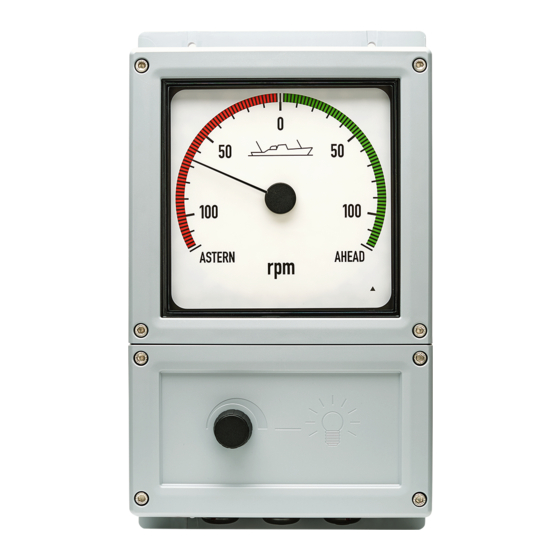
Bridge wing indicator
Hide thumbs
Also See for BRW-2:
- Quick manual (2 pages) ,
- Installation and commissioning manual (39 pages) ,
- Quick manual (4 pages)
Advertisement
Table of Contents
Advertisement
Table of Contents

Subscribe to Our Youtube Channel
Related Manuals for Deif BRW-2


Summary of Contents for Deif BRW-2
- Page 1 BRW-2 Bridge wing indicator Quick guide...
- Page 2 1. Mounting the unit Dimensions and drilling plate NOTE The three PG21 type cable glands on the bottom of the unit are suitable for cable gauge 13 to 18 mm. QUICK START GUIDE 4189350056B UK Page 2 of 4...
- Page 3 Analogue version There is a “maximum” and a “zero” adjustment on the rear side of the XL part. These are factory-sealed. BRW-2 analogue input: See the user's manual for guidance on how to adjust this version. Terminal connections on interface board Pin no.
- Page 4 3. sCAN version Setup Special means for minimum, zero and maximum setting of the pointer are provided. Pointer direction of rotation can also be changed. Wiring of CAN version Use strips to terminate cable shields to PCB to avoid noise (see the dashed circles in the diagram). Jumpers J1 and J2 are used to connect CAN 1 and CAN 2 termination resistors.
Need help?
Do you have a question about the BRW-2 and is the answer not in the manual?
Questions and answers