Table of Contents
Advertisement
Advertisement
Table of Contents

Related Manuals for Clemco SCW-2040


Summary of Contents for Clemco SCW-2040
- Page 1 OWNER’S MANUAL Single Chamber Blast Machine for 1 Operator with manual or pneumatic media metering valve Clemco International GmbH Carl-Zeiss-Straße 21 Tel.: +49 (0) 8062 – 90080 83052 Bruckmühl Mail: info@clemco.de Germany Web: www.clemco-international.com Revision: 3...
-
Page 2: Table Of Contents
YOUR BLAST MACHINE Standard Pneumatically Electric remote Dual function Dual function operated media controls pneumatic electric metering valve TABLE OF CONTENTS SCOPE OF MANUAL ................... 4 APPLICATION AND RESTRICTIONS ..............5 GENERAL DESCRIPTION ..................5 ..................5 TANDARD BLAST MACHINE 3.1.1 How the system works ...................... - Page 3 ..................... 17 AILY CHECK LIST ....................17 EEKLY CHECK LIST ....................18 ONTHLY CHECK LIST TROUBLE-SHOOTING ..................18 REPLACEMENT PARTS ..................20 1440 – 2460 .................. 21 LAST ACHINES ................. 23 LAST ACHINES IGHTY RME-1 / -2..................23 LECTRIC PANEL...
-
Page 4: Scope Of Manual
1 Scope of manual This manual covers operation and maintenance for the following single chamber blast machines with pneumatic or electric remote controls and manually or pneumatically operated media metering valves: Volumina Model Max. pressure [bar] Remote Control Valve Metering valve When using RMS-2000A RMM-50A... -
Page 5: Application And Restrictions
2 Application and restrictions Single chamber blast machines can be used with all types of abrasive (60 – degree conical bottom for fine mesh abrasive on option). Table 1 shows the maximum working pressure for the different models available. Higher working pressure is possible only for special designs. The following options are recommended: −... -
Page 6: How The System Works
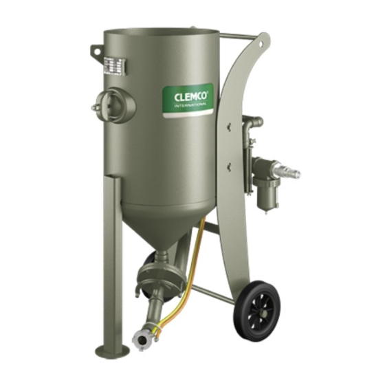
Figure 1 shows the major components of the standard blast machine: • Pot with − remote control valve RMS-2000A (RMS 1500+500) or RMM-50A (item 2). − muffler (item 5). − moisture separator (item 4). − media metering valve (item 3) manually or pneumatically operated. −... -
Page 7: Blast Machine With Pneumatically Operated Media Metering Valve
3.2 Blast machine with pneumatically operated media metering valve Figure 2: Blast machine with pneumatically operated metering valve and pneumatic remote controls. Principle of operation: same as the standard pressure blasting device. When the deadman handle (item 6) is depressed the metering valve opens, when it is released, the metering valve closes. -
Page 8: Optional Electric Remote Controls
3.3 Optional electric remote controls Figure 3: Electric remote controls and pneumatically or manually operated abrasive metering valve. In order to reduce the time to stop blasting (especially when using longer blast hoses), the twinline hose between the deadman handle and the remote control valve is replaced by an electric cord (orange) and the electric panel RME-1 (item 15). -
Page 9: Dual Function Pneumatic
3.4.1 Dual function pneumatic An additional 3-way slide valve (pos. 6.1) enables the operator to open or close the metering valve when the deadman handle is depressed. When the slide of the 3-way valve is moved to the left the abrasive metering valve opens, to the right it is closed again. -
Page 10: Dual Function Electro-Pneumatic
3.4.2 Dual function electro-pneumatic Figure 5: Dual function electric. An additional electrical switch on the deadman handle enables the operator to open or close the pneumatically operated metering valve when the deadman handle is depressed. A magnetic valve mounted on the electric control panel RME-2 (item 15) converts the electric signal into a pneumatic signal. - Page 11 Principle of operation: Compressed air is supplied to the system via a HMS water separator (item 4). The air is fed into the RMS 2000 remote control valve (item 2) and from there via the port 2A (brown remote control hose) to the deadman handle (item 6) and to the pressure regulator (1/4"...
-
Page 12: Pneumatic Remote Control With Dual Function And Rms 2000 Remote Control Valve
(between 2 and 15 seconds) to less than 1 second. German law demands this equipment. CLEMCO recommends to use a Quick Stop System for the following applications in other countries: • Blast pressure ≥ 5 bar • Length of blast hose ≥ 20 m •... - Page 13 Figure 6: Quick Stop System SSAS1 Legend: 1 Blast pot with: - 2 Remote Control (example RMS 2000) - 3 Abrasive metering valve - 4 Non return valve 5 Abrasive hose between pot and SSAS1 6 Control hose 7 Abrasive hose between SSAS and nozzle (max. 10 m) 8 Nozzle holder with nozzle 9 Electric remote control handle and control cord RLX-E 10 Quick stop system SSAS with:...
-
Page 14: Set-Up And Operation
5 Set-up and operation 5.1 Requirements For a proper function of the blast machine, a sufficient air supply is necessary (see table 2). Nozzle Air consumption [m /min.] size [mm] Pressure at the nozzle [bar] 10.1 12.0 12.5 10.7 13.1 15.4 Table 2: Air consumption 5.2 Set-up for initial installation or reinstallation... - Page 15 remote control hoses ⇒ Connect twinline hose (yellow/brown) (pneumatic controls) or an corresponding twinline hose (yellow/brown) coming electric cord and the electric from remote control valve RMS-2000A or RMM 50A. panel RME (electric remote ⇒ Connect yellow and brown remote control hose to controls).
-
Page 16: Daily Set-Up
5.3 Daily set-up Not necessary if an initial installation or reinstallation was performed (see section 5.2). (1) Air supply. Start compressor and bring it up to operating temperature (5 to 10min.). − Abrasive-resistant clothing. (2) Put on protective equipment. − Airfed helmet with connection to breathing air supply (air filter) and adjustment of air volume with an air control valve attached to belt. -
Page 17: Shut-Down
5.5 Shut-down (1) Empty all abrasive. Blast machine not in use > 1 day (abrasive could get moisture). 5.6 Shut-down when moving equipment No special measures required. 6 Maintenance 6.1 General During operation blast machines are exposed to wear. In order to ensure safe operation and high efficiency the blast machines should be maintained according to the following check lists. -
Page 18: Monthly Check List
detected. − Check airline (air supply) and replace it when it is worn. − Check gaskets of couplings for wear and replace them if necessary. 6.4 Monthly check list (1) Remote control valve RMS- Check all fittings and connections of remote control valve for 2000A (RMS 1500+500) or leakage. - Page 19 (4) Too much abrasive comes Abrasive metering valve too Check and correct adjustments. out of nozzle. much opened. Choke valve not completely Check and open it completely if opened. necessary. (5) Pop-up valve does not Insufficient air volume or Check air pressure of remain closed.
-
Page 20: Replacement Parts
8 Replacement parts Figure 7: Replacement parts. -
Page 21: Blast Machines 1440 - 2460
8.1 Blast Machines 1440 – 2460 Pos. Part no. Description Model 1440 1638 2040 2048 2452 2460 90550D P-8-R Y-piece 1 ¼“ rubbered 90552D Hex nipple P32 1 ¼“rubbered ... - Page 22 (18) 02331D Screen for 1628, 1638, 1648 02332D Screen for 2452, 2460 90561D Screen for 2040, 2048 90661D Screen insert for 1440 90662D Screen insert for 1628 90663D Screen insert for 2040, 2048 ...
-
Page 23: Blast Machines Mighty Mite
8.2 Blast Machines Mighty Mite Stock No. Description Model 1028 1628 99093D Safety ring for wheel 1028 90002D KAG-12 Air coupling 1/2“ 93050D Fitting kit for RMM-50A / 1028 90211D RMM 50A, Remote control with silencer and RLX-III ... - Page 24 Stock No. Description 90640D RME electric panel 230V power supply with deadman handle RLX-E 90887D RME-1 electric panel 230/12V with deadman handle RLX-E 90890D RME-230/12V electric panel 90888D RME-2 electric panel with RLX-E for dual function 90891D RME-2A electric panel for dual function without deadman handle 93126D ¼“...
Need help?
Do you have a question about the SCW-2040 and is the answer not in the manual?
Questions and answers