Table of Contents
Advertisement
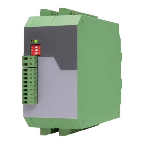
Operating Manual
Pulse splitters for incremental encoders with and without potential separation
Product features:
•
Power supply from 10 up to 30 VDC
•
1 encoder input for channels A, /A, B, /B, Z, /Z
•
Input levels selectable between RS422, TTL and HTL
•
Optionally types with 2, 4 or 8 outputs with or without potential separation available (see below)
•
Output levels are specified by external power supply
•
Short-circuit proof +5VDC and +24VDC encoder supply
Available devices:
• GV224:
• GV228:
• GV228/EV:
• GT222:
• GT224:
• GT228:
• GT228/ET:
motrona GmbH, Zeppelinstraße 16, DE - 78244 Gottmadingen, Tel. +49 (0) 7731 9332-0, Fax +49 (0) 7731 9332-30, info@motrona.com, www.motrona.com
GV224 / GV228
GT222 / GT224 / GT228
Pulse splitter with 1 encoder input and 4 outputs
Pulse splitter with 1 encoder input and 8 outputs
Pulse splitter with 1 encoder input and 8 outputs
with extension option for 4 or 8 outputs (EV224 / EV228)
Pulse splitter with 1 encoder input and 2 potential separated outputs
Pulse splitter with 1 encoder input and 4 potential separated outputs
Pulse splitter with 1 encoder input and 8 potential separated outputs
Pulse splitter with 1 encoder input and 8 potential separated outputs
with extension option for 4 or 8 potential separated outputs (ET224 / ET228)
Advertisement
Table of Contents

Related Manuals for Motrona GT224


Summarization of Contents
Safety Instructions and Responsibility
General Safety Instructions
Essential safety rules and operational hints for device usage and preventing hazards.
Intended Use
Guidelines for using the device according to its specified industrial applications.
Installation Guidelines
Procedures and precautions for the safe and correct installation of the device.
EMC Guidelines
Measures to minimize electromagnetic interference for reliable operation.
Cleaning, Maintenance, and Service
Instructions for cleaning, routine maintenance, and service procedures.
Introduction and Block Diagrams
Block Diagram GV224 and GV228
Illustrates the functional principle and signal flow for GV224 and GV228 models.
Block Diagram GT222, GT224, GT228
Shows the operational principle and signal paths for GT222, GT224, and GT228 models.
Electrical Connections and LED Functions
Power Supply and LEDs
Details power input requirements and the function of the device's status LEDs.
Auxiliary Encoder Supply
Information on the dedicated encoder supply terminals and their specifications.
Impuls Input Configurations
Settings for various encoder input signal types (HTL, RS422, TTL) via DIL switches.
Impuls Outputs
Characteristics and requirements for the device's pulse output signals.
Error Evaluation
How to activate and interpret error detection for input channels.
Need help?
Do you have a question about the GT224 and is the answer not in the manual?
Questions and answers