Table of Contents
Advertisement
Advertisement
Table of Contents

Related Manuals for Konica Minolta DR1600


Summary of Contents for Konica Minolta DR1600
- Page 2 WARNING This equipment has been tested and found to comply with the limits for a Class A digital device, pursuant to Part 15 of the FCC Rules. These limits are designed to provide reasonable protection against harmful interference when the equipment generates, uses, and can radiate radio frequency energy and, if not installed and used in accordance with the instruction manual, may cause harmful interference to radio communications.
-
Page 3: Safety Information
Installation and Operation Precautions Safety Information This section contains detailed instructions on the operation and maintenance of this machine. To achieve optimum utility of this device, all operators should carefully read and follow the instructions in this manual. Please read the following section before connecting the machine to the supply. It contains important in- formation related to user safety and preventing equipment problems. - Page 4 Disassemble and modification WARNING • Do not attempt to remove the covers and panels which have been fixed to the product. Some products have a high-volt- age part or a laser beam source inside that could cause an electrical shock or blindness. •...
- Page 5 Power source WARNING • Use only the specified power source voltage. Failure to do that could result in a fire or electrical shock. • Connect power plug directly into wall outlet having the same configuration as the plug. Use of an adapter leads to the product connecting to inadequate power supply (voltage, current capacity, grounding), and may result in fire or shock.
- Page 6 Installation WARNING • Do not place a flower vase or other container that contains water, or metal clips or other small metallic objects on this product. Spilled water or metallic objects dropped inside the product could result in a fire, electrical shock, or breakdown. Should a piece of metal, water, or any other similar foreign matter get inside the product, immediately turn OFF the power switch, unplug the power cord from the power outlet,...
- Page 7 Actions in response to troubles WARNING • Do not keep using this product, if this product becomes in- ordinately hot or emits smoke, or unusual odor or noise. Im- mediately turn OFF the power switch, unplug the power cord from the power outlet, and then call your authorized service representative.
-
Page 8: Table Of Contents
CONTENTS SPECIFICATIONS....................1 INSTALLATION ....................2 PARTS IDENTIFICATION ..................4 CONTROL PANEL KEYS AND INDICATORS ............. 6 REMOVING AND INSTALLING THE FILM UNIT..........8 FILMING PROCEDURE ..................9 LOADING AND UNLOADING FILM ..............10 SPACING......................14 RELATIONSHIP BETWEEN DOCUMENT SIZE AND MAGNIFICATION..15 TAKING A STEP TEST .................. -
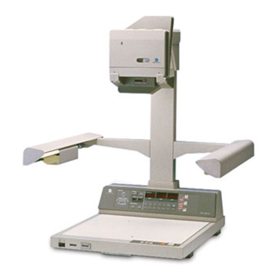
Page 9: Specifications
SPECIFICATIONS ■ Type: : Planetary Microfilmer ■ Lens: : Micro-Rokkor f = 28 mm ■ Film: : 16-mm Roll Film (Non-Perforated) 5 mil - 100 ft., 2.5 mil - 215 ft. ■ Document Size: : Max. 17” x 11” or A3 ■... -
Page 10: Installation
INSTALLATION ■ INSTALLATION ■ Space Requirements To ensure easy operation and service the machine requires the following installation space. - Page 11 ■ Installation Site To prevent the machine from developing malfunction and to ensure its best possible performance, avoid installing the machine in a place: • Which is exposed to direct sunlight. • Which is immediately under a light. • Which is near a bright window. •...
-
Page 12: Parts Identification
PARTS IDENTIFICATION ■ PARTS IDENTIFICATION Power ON/OFF Switch: Used to turn ON and OFF the machine. Shutter Button: Press this Button to make an exposure, advancing film to the next frame. Stop Key: Press this Key to stop advancing the film or beeps sounding. Spacing Key: Press and release this Key to skip one frame between images without exposure. - Page 13 ■ FILM UNIT Film Supply Indicator Displays the length of usable, unexposed film left in the Film Unit in (2.5 mil, 5 mil): meters or feet. Film Door Lock: Locks and unlocks the Film Take-Up Door. Film Movement Indicator: The stripes in the window move while the film is being advanced during filming.
-
Page 14: Control Panel Keys And Indicators
CONTROL PANEL KEYS AND INDICATORS ■ CONTROL PANEL KEYS AND INDICATORS Document Mark Level Select Key: Press this Key to select the document-mark recording level, either 0, 1, 2, or 3. The lit indicator , or indicates the level currently selected for use. - Page 15 Leader/Trailer Key Press this Key to allow for setting the number of unexposed frames to be (Variable Setting): advanced between images at any desired number. When the Key is pressed, its indicator lights up and the Displays goes out. Then, enter any desired number using a Number Key or Keys. When the Leader/Trailer Key is pressed a second time, the machine advances the set number of unexpose frames and the old data reappears on the BLOCK display.
-
Page 16: Removing And Installing The Film Unit
REMOVING AND INSTALLING THE FILM UNIT NOTE When removing and installing the Film Unit, make sure that the Power ON/OFF Switch is turned OFF. The Film Unit should be removed and installed where it is in a 1/25 reduction ratio position. ❑... -
Page 17: Filming Procedure
FILMING PROCEDURE ■ FILMING PROCEDURE Load film. Advance film 50 to 100 frames. Set reduction ratio - Auto, 1/25, or 1/32. Set frame size - Auto, Single, or Double. Select document mark level - 0, 1, 2, or 3. Select frame number mode - OFF, 12 digits (A, B, C), 8 digits, 4 digits or OFF. -
Page 18: Loading And Unloading Film
LOADING AND UNLOADING FILM ■ LOADING AND UNLOADING FILM NOTE It is recommended to use a dark room when load or unload film to prevent fogging effect. 1. Loading Film Place the Film Unit on its side as illustrated. Turn the Film Door Lock in the direction of arrow (counterclockwise) to open the Take-Up Door. - Page 19 Select the thickness of film loaded using the Film Thickness Select Switch, either 2.5 mil or 5 mil. NOTE If a wrong setting is made, the Film Supply Indicator and alarm will function incorrectly. Install the Film Unit to the Film Unit Mounting Board and turn ON the DR1600MKII with the Power ON/OFF Switch.
- Page 20 Turn the Film Door Lock in the direction of arrow and open the Take-Up Door. With your fingertips, hold the film down in the Take-Up Spool to prevent it from unraveling. While so doing, cut off the film. Remove the Take-Up Spool from the Take-Up Spindle and place it into a light-proof container.
- Page 21 ❑ Unloading Full Roll: Press [STOP] Key to stop the beeps sounding. Immediately stop filming and, using the Spacing Key, advance film until it is completely wound around the Take-Up Spool. Turn Power ON/OFF Switch off, then, remove the Film Unit from the Film Unit Mounting Board. NOTE Additional exposures can be taken even after the beeps have sounded and the Film Empty Indicator has lit;...
-
Page 22: Spacing
SPACING ■ SPACING ■ Single Frame: Depress the Spacing Key. NOTE Holding this key down will advance the film continuously. ■ Prefixed Number of frames: ❑ by using key, can be selected any desired number of frames between 1 and 9999 to be advanced. (See page 7) ❑... -
Page 23: Relationship Between Document Size And Magnification
RELATIONSHIP BETWEEN DOCUMENT SIZE AND MAGNIFICATION ■ RELATIONSHIP BETWEEN DOCUMENT SIZE AND MAGNIFICATION The relationship between the document size and applicable reduction size is shown below. If, therefore, AUTO is selected with the Reduction Ratio Select Key and Frame Size Select Key, the reduction ratio and frame size are automatically determined according to the size of the document to be filmed. -
Page 24: Taking A Step Test
TAKING A STEP TEST ■ TAKING A STEP TEST A step test can be taken by using the Leader/Trailer Key (Variable Setting). This test verifies the exposure condition by filming a single document consecutively for a number of frames. A step test is necessary when a different film is used, when a different processing chemical is used, and when the film unit is new. -
Page 25: Microfilming
MICROFILMING ■ Microfilming on DR1600MKII Place the document face up on the Copy Board so that its front left edge is held tight up against the “ ” mark on the Board, then press the Shutter Button. NOTE Up to 20-mm(25/32”)-thick document microfilmed in focus. -
Page 26: Recording Document Mark
RECORDING DOCUMENT MARK ■ RECORDING DOCUMENT MARK A document mark can be generated on each image or frame of a roll of microfilm for indexing purposes. It is recorded on the A-ch side (bottom side) of a roll by the following procedure. Press the Document Mark Level Select Key as many times as it is required to select the desired recording level. - Page 27 Dual-Level Recording When you place a batch document on the Copy Board, press the Batch Key (Indicator will light-up)., then press the Shutter Button. When you place an item document, directly press the Shutter Button. Tri-Level Recording When you place a block document on the Copy Board, press the Block Key (Indicator will light-up)., then press the Shutter Button.
-
Page 28: Recording Frame Number
RECORDING FRAME NUMBER ■ RECORDING FRAME NUMBER In addition to the document marks, a frame number can also be recorded on the B-ch side at top left of each image or frame of a roll of microfilm for indexing purposes. A frame number may consist of 4 digits, 8 digits (4 digits x 2 fields), or 12 digits (4 digits x 3 fields). - Page 29 8-digit Display -To record the number corresponding to the medium document mark (the second 4-digit field), press the Batch Key, then press the Shutter Button. -To record the number corresponding to the small document mark (the third 4-digit field), directly press the Shutter Button.
-
Page 30: Manual Exposure Mode
MANUAL EXPOSURE MODE ■ MANUAL EXPOSURE MODE If the Auto Exposure Mode fails to produce optimum exposure condition, the Manual Exposure Mode can be used for better microfilming results. When in the Manual Exposure Mode, the machine allows you to vary the exposure time in the range between 50 ms and 2,000 ms. -
Page 31: Choice Modes
CHOICE MODES ■ CHOICE MODES The microfilmer offers ten Choice Modes, CH2 to CH8, allowing you to define the various priority modes which are automatically selected when the machine is turned ON. 1. Mode Setting Procedure Press the Mode Choice Key. Then, “... - Page 32 2. Details of Each Choice Mode Mode Number Description Document mark recording level No document mark Single-level recording Dual-level recording Tri-level recording Single-level document mark size Dual-level document mark size (combination)
- Page 33 Mode Number Description Frame number display (no. of digits) 12-digit A-mode When BLOCK Key is pressed: BLOCK - Incremented by one BATCH - Reset to 0000 ITEM - Reset to 0001 When BATCH Key is pressed: BLOCK - Not incremented BATCH - Incremented by one ITEM - Reset to 0001...
- Page 34 2. Details of Each Choice Mode Mode Number Description The number of frames to be skipped, as effected by the Leader/Trailer Key (Fixed Setting) Film advance pitch (Pulldown) Document mark recording position. The position of the 2.3 mm width mark in single-level recording can only be varied.
-
Page 35: Maintenance And Services
MAINTENANCE AND SERVICES ■ MAINTENANCE AND SERVICES 1. Replacing the Illumination Lamp When the ends of a fluorescent lamp turn black, it indicates that the lamp needs replacement. To ensure even illumination over the entire surface of the Copy Board, replace the old lamp with a new one. NOTE The two fluorescent lamps should be replaced at once. - Page 36 2. Cleaning Dust and dirt impair performance of any optical equipment. Keep the microfilmer clean at all times. Film Unit ❍ Wipe clean of dirt the interior of Take-Up and Supply Rooms and the Lens. After a roll of film has been removed from the Unit, always close the Doors in position and face the Lens downward for storage.
-
Page 37: Potential Problems
POTENTIAL PROBLEMS When any error message occurs in the Microfilmer, an error message appears on the display, the Shutter Button turns red, and microfilm advancing stop. In this case, check the error code (numbers following the letter “E”) and call your authorized Service Representative. Error Code Possible Cause Description... -
Page 38: Troubleshooting
TROUBLESHOOTING ■ TROUBLESHOOTING Symptom Possible Cause Remedy Power is not supplied to microfilmer • Power Cord is not plugged into • Plug the Power Cord into outlet. ❍ even when the Power ON/OFF outlet. Switch is turned ON. Lamps do not come on (including •... -
Page 39: Supplement
SUPPLEMENT ■ Maintenance the Document Pressure Glass. As a document is being fed, the Document Pressure Glass and the Document Transport Belt became electrostatically changed. This causes a rise in the coefficient of friction. As a result, a document might be transported skewed or might misfeed. If skewed document feeding or an inordinate number of document misfeed occurs, polish the back side of the Document Pressure Glass with metallic car wax. -
Page 40: For Key Operators Use
For Key Operators Use When you need to call for service, the Key Operator should be prepared to provide the following information: 1. Your Company Name, Address, Telephone No., Dept. No., Floor No., Machine Location etc. 2. Model name, Serial number, Condition or System(s) Indication on Display etc. For your reference purpose.
Need help?
Do you have a question about the DR1600 and is the answer not in the manual?
Questions and answers